 Nenghong Xia*
 Shuang Yan
 Huaqi Ma
95% of researchers rate our articles as excellent or good
Learn more about the work of our research integrity team to safeguard the quality of each article we publish.
Find out more
ORIGINAL RESEARCH article
Front. Energy Res. , 22 February 2024
Sec. Process and Energy Systems Engineering
Volume 12 - 2024 | https://doi.org/10.3389/fenrg.2024.1343247
The LLC resonant converter used in high-power situations suffers from the problems of high conduction loss and current stress, which can be solved using input-parallel output-parallel (IPOP)-connected converter modules. However, this leads to a multiple increase in the number of magnetic components, which reduces power density. Magnetic integration technology is an effective way to reduce the volume of converters. Currently, the magnetic integrated transformer based on EE-type cores is widely used to realize miniaturization, and it uses leakage inductance instead of resonant inductance to improve power density. However, leakage inductance is difficult to control, and the external radiated magnetic field will produce serious eddy current loss and electromagnetic interference. This article proposes a novel double B-type magnetic integrated transformer, which can integrate the magnetic components of two LLC resonant converters simultaneously and where the resonant inductances are wound independently. The structure contains four low reluctance branches, which are used as the cores of the transformer and the resonant inductance. The decoupling integration method, which integrates the four components into a single core, has been used to increase core utilization and improve power density. On this basis, the transformer’s high- and low-voltage windings are cross-arranged to reduce the magnetic field intensity in space, further decreasing the loss and electromagnetic interference. Compared with the EE-type magnetic integrated transformer, the volume of the proposed structure is reduced by 5.9%. A 400W experimental prototype is built, and the results verify the validity of the design.
With the rapid development of power electronic technology, isolated high-frequency DC-DC power converters are widely used in electric vehicles, renewable energy, energy storage systems, and DC power grid fields (Li et al., 2019; Guan et al., 2021; Bughneda et al., 2022; Ievgen et al., 2022; Vijayakumar and Sudhakar, 2022; Liu et al., 2023). Among the various topologies, the LLC resonant converter has been focused on extensively by scholars due to its smooth waveform, high power density, low voltage stress, and the ability to achieve zero voltage switching (ZVS) for the primary-side switches and zero current switching (ZCS) for the secondary-side rectifier diodes (Zeng et al., 2020). However, as the power level of the application increases, a single LLC resonant converter faces serious problems, such as high conduction loss on the primary side, high current stress on the secondary side, and large output current ripple. Connecting multiple low-power LLC resonant converters by input-parallel output-parallel (IPOP) to apply in high-power conditions can solve all the abovementioned problems (Ahmad et al., 2021). However, this also causes a considerable increase in power converters. The weight and volume of magnetic components such as inductances and transformers account for about 30%–40% of the whole (Gao and Wang, 2020), becoming the main constraints to improving efficiency and power density. Magnetic integration technology effectively improves power density by structurally concentrating multiple discrete magnetic components on a single core without affecting regular operation.
Most conventional magnetic integrated transformer structures are based on EE-type cores. Setting air gaps to increase the leakage inductance replaces the resonant inductance. Although it can reduce the size of magnetic components, there are also problems, including uneven flux distribution on the core (Yang et al., 2021) and electromagnetic interference (Chen et al., 2022). Some scholars have studied the leakage flux and losses of LLC resonant converters. For example, (Noah et al., 2019a; Noah et al., 2019b; Mostafa et al., 2020), deeply discussed the effect of leakage inductance on the operation of LLC resonant converters and separately characterized the leakage inductance on the primary and secondary windings in terms of the primary coupling factor k1 and secondary coupling factor k2. The leakage inductance distribution was controlled by the windings’ design. Moreover, (Kimura et al., 2016), proposed a novel core calculation model and compared the volume and loss of three converters using close-coupled inductors (CCIs), loosely coupled inductors (LCIs), and integrated winding coupled inductors (IWCIs), which provided an effective method for the downsizing of magnetic components. Regarding the magnetic integrated transformer structure, (Yang et al., 2022), proposed an integrated winding structure with a negligible external magnetic field for resonant converters. The windings were sectioned and interleaved by inserting a magnetic shunt in the core, which reduced the length of the crossed sections of the windings while making the magnetic flux generated by external winding sections with cancelation performance. In addition, (Gao and Zhao, 2021), designed a magnetic integrated structure with an independent inductance LLC resonant converter. The resonant inductance and transformer were integrated into a single core using the decoupled integration method, thereby reducing the leakage inductance and lowering the losses. Furthermore (Park and Han, 2021; Ansari et al., 2022; Li et al., 2022), integrated the magnetic components of the DC-DC converter in different forms. Although the converter’s power density is improved, there are still deficiencies in core saturation, leakage flux, and converter efficiency.
This article proposes a double B-type magnetic integrated transformer that can simultaneously integrate four magnetic components, comprising two transformers and two independent resonant inductances, to solve problems such as power density reduction, caused by multiple magnetic components in the IPOP converter system, and eddy current loss, caused by the spatial leakage flux of the traditional magnetic integrated approaches. The magnetic circuit coupling characteristic has been analyzed, and the design method of the magnetic core has been given. The proposed structure has been compared with the EE-type structure in terms of power density and efficiency. A prototype has been built to test its performance.
The IPOP two LLC resonant converters system is shown in Figure 1. L1, L2, T1, and T2 are the four magnetic components (two resonant inductances and two transformers). The conventional magnetic integrated structure uses EE-type cores, where the windings of two transformers are wound on the outer columns, and the magnetic flux is unevenly distributed in the core (Gao and Zhao, 2021). The overall increase in the core volume to prevent local saturation will reduce the power density, resulting in material waste. Moreover, the air gap is usually opened on the outer core columns, which leads to a massive flux around the core. These fluxes will cause a decrease in transformer efficiency while generating eddy current losses in the metal devices near the magnetic integrated structure, resulting in serious heat generation (Yang et al., 2021).
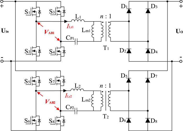
Figure 1. IPOP two LLC resonant converter system.
This article designs a novel magnetic integrated transformer structure with two transformer windings wound on the center column of the core, as shown in Figure 2. The structure resembles two face-to-face B, and the internal contains four low reluctance branches. The air gaps are placed on the left and right core columns. The primary and secondary windings of two transformers are wound on the left and right core columns, and the flux flows back to the windings along their respective low reluctance branches with uniform distribution throughout the core. The wrapping of the outer core reduces the leakage flux.
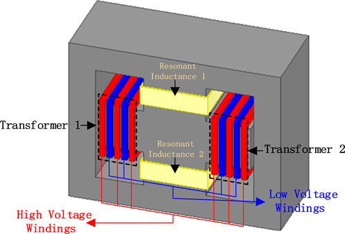
Figure 2. Double B-type Magnetic Integrated Transformer.
In terms of the transformer winding design, the high- and low-voltage windings reverse staggered winding. As shown in Figure 2, the red and blue coils represent the high- and low-voltage windings, respectively. This practice can enhance the coupling between the transformer windings and further weaken the external magnetic field intensity by flux cancelation performance (Yang et al., 2022).
In order to further improve the power density, it is typical to use leakage inductance instead of resonant inductance (Zhang et al., 2021). However, there are many disadvantages to this approach:
1) Leakage inductance is hard to control accurately, and it is difficult to make leakage inductance large enough due to the limitation of the core size, while the voltage gain of the LLC resonant converter is very sensitive to the value of resonant inductance;
2) Increased leakage flux will cause a decrease in transformer efficiency;
3) Massive leakage flux can also cause serious electromagnetic interference, and secondary-side leakage inductance will cause the rectifier diode pass-state loss to increase (Gao and Zhao, 2021).
Therefore, this article adopts the individually wound resonant inductance, while the role of the air gap of the core is only to reduce the permeability. The two resonant inductances are wound on the upper and lower core columns, decoupled, and integrated with the two transformers. The final double B-type structure integrating four components is shown in Figure 2. Since the parameters of the two LLC resonant converters are identical, the windings are symmetrically distributed on the four inner core columns. This approach improves the power density while increasing the utilization of the core.
The equivalent magnetic circuit model of the double B-type magnetic integrated transformer is shown in Figure 3. N11, N12 and N21, N22, are the primary and secondary windings of the two transformers, respectively; ir1, is1 and ir2, is2 are the currents flowing into the four windings; N11ir1, N12is1, and N21ir2, N22is2 are the magnetic electromotive forces of the four windings; N3 and N4 are the independent wound resonance inductances of the two LLC resonance converters; i3 and i4 are the currents flowing into the two inductances; N3i3 and N4i4 are the magnetic electromotive forces of the two inductances. Ф1, Ф2, Ф3, and Ф4 are the main flux under the joint action of the windings in the magnetic core that does not take into account the leakage flux of the air gap edges and windings; and R01, R02, and R03 are the reluctance of each branch, of which R01 contains the air gap reluctance Rg. Since the two converters have the same parameters, the turns of the two transformers’ primary and secondary windings are N11 = N21, N12 = N22, and the turns of two resonant inductances are N3 = N4.
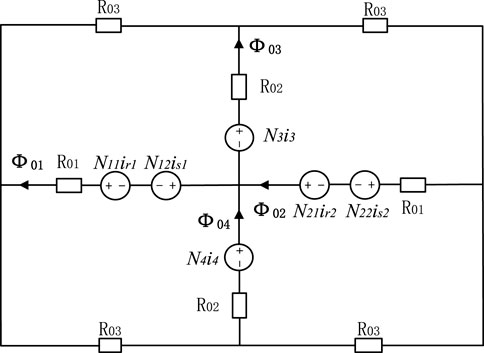
Figure 3. Magnetic circuit model of the double B-type magnetic integrated transformer.
According to Ohm’s law for magnetic circuits, the windings of the transformer and the inductance produce fluxes are expressed as
Where
In Eq. 1,//means parallel connection. Since the equivalent magnetic circuit model of the double B-type core structure is symmetric, the equivalent reluctance RiL is calculated from the two ends of the inductance as interchanging R01 and R02 in RiT (i = 1, 2, 3, a, b, c). On this basis, the magnetic flux generated on the four core columns under the joint action of the windings can be determined as
Where
Where
According to the electromagnetic induction law, the transformer voltages UT1, UT2, and inductance voltages UL3, UL4 can be obtained as
Substituting Eq. 5 into Eq. 7 results in Eq. 8
The values of the elements of the matrix can be expressed as
It is known that RaT = RbT, and since R01 contains the magnetoresistance of the air gap, R01>>R02, it can be determined that
In summary, the double B-type magnetic integrated structure achieves decoupling integration between the resonant inductances and transformers.
This section focuses on the design process of the proposed structure, selecting a transformer with input/output voltages of 360/48V for the purpose, and the parameters are shown in Table 1.
1) Selection of core dimension and material: From the cost, saturation flux density, relative permeability, and resistivity of four considerations, PC40 ferrite is selected as the core material. It has a relative permeability of µ = 2,300 and saturation flux density of Bsat = 0.3T at 100°C.
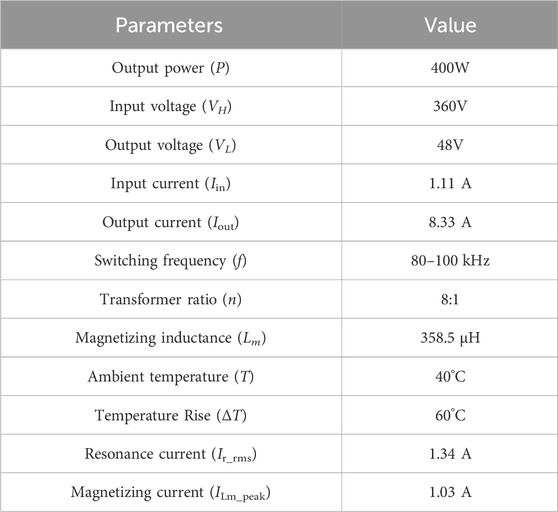
Table 1. Transformer parameters.
The dimension is designed using the Ap value method. The calculation equation can be given by (Yang et al., 2021)
Where ku is the window utilization coefficient; γ is the ratio of iron loss to copper loss of the transformer; ΔT is the temperature rise; Lm, ILm_peak, and Ir_rms are the magnetizing inductance, peak magnetization current, and resonance current RMS of the converter, respectively; Bmax is the maximum flux density; Kt is the geometrical constant; and kup is the primary winding window utilization coefficient. In order to prevent core oversaturation, the maximum flux density in this article is designed to be Bmax = 0.2T. Selecting γ = 1, ku = 0.4, and Kt = 48.2×10³, which are brought into Eq. 11, results in the calculation of Ap = 0.2463 cm4. The parameters of the designed core dimensions are shown in Figure 4, and the parameters are substituted into
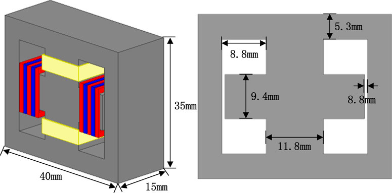
Figure 4. Proposed transformer core dimensions.
Where Aw is the effective cross-sectional area of the core column, and Ae is the window area. The Ap of the selected core is calculated as
Therefore, the design of the core has to satisfy the requirements.
2) Determination of the winding turns and length of the air gap: The design of the winding turns should avoid the saturation of the branch core.
For the transformer’s primary winding turns, the design is based on obtaining the maximum magnetic flux density at the minimum operating frequency, and the secondary-side calculation is based on the transformer ratio and the conduction voltage drop of the output rectifier.
Where Kf is the waveform factor of the square wave on the high-voltage side, take Kf = 4, and the rest of the parameters are shown in Table 1. By calculating, finally, take N11 = N11 = 39, N12 = N22 = 5.
The air gaps on the left and right sides are the same length, and the calculation application equation can be expressed as:
Where Rg is the required air gap reluctance; µ0 is the air permeability, which is 4π×10−7H/m; δ is the length of the air gap; and A1 is the cross-sectional area of the left and right center columns of the core, A1 = 138 mm2.
From Eqs 5, 6, 9, it follows that
Since R01≈Rg is much larger than R02 and R03, ReqT ˜ Rg, and Req3T≈1. This yields Rg = 4.87 × 10⁶H.
The length of the air gap is calculated to be
The resonant inductance, according to (Li et al., 2018), can be calculated as
After calculation, the turns of resonant inductance are taken as N3 = N4 = 9. Then, the design of the double B-type magnetic integrated transformer structure is completed.
The magnetic integrated transformers based on a double B-type and EE-type core are simulated using ANSYS Maxwell. The parameters of the EE-type core are shown in Table 2, and the magnetic flux density distributions of the two cores are compared, as shown in Figure 5. The ferrite saturation flux density is 0.3 T. It can be seen that neither type of transformer is saturated in the core during regular operation, proving the design’s rationality. When only two transformers are integrated on the double B-type core, the upper and lower core columns have non-utilized regions due to flux cancellation performance. Placing the resonant inductance here can utilize this region, and the overall magnetic flux density distribution simulation is shown in Figure 6. The comparison between Figures 5, 6 shows that the magnetic flux density distribution uniformity is better in the double B-type core. There is a flux-canceling region in the middle column of the EE-type core. The utilization adequacy of the core is lower than that of the double B-type core.
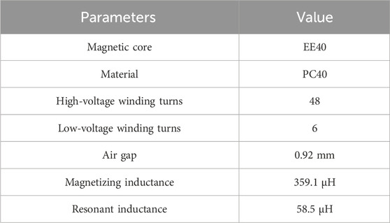
Table 2. EE-type transformer structure parameters.
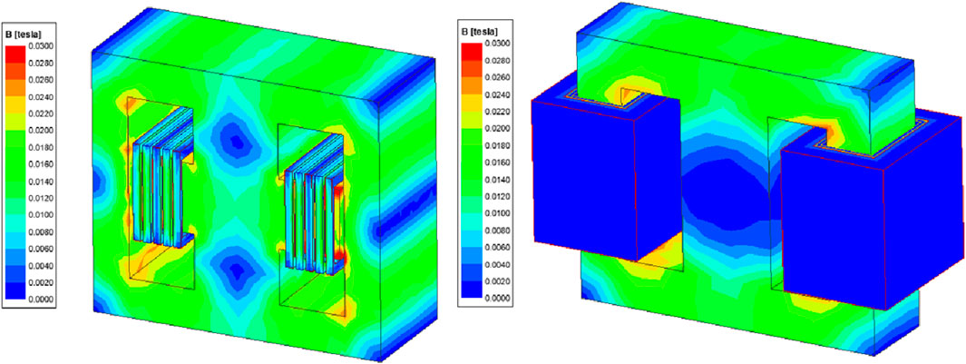
Figure 5. Magnetic flux density distribution of the core.
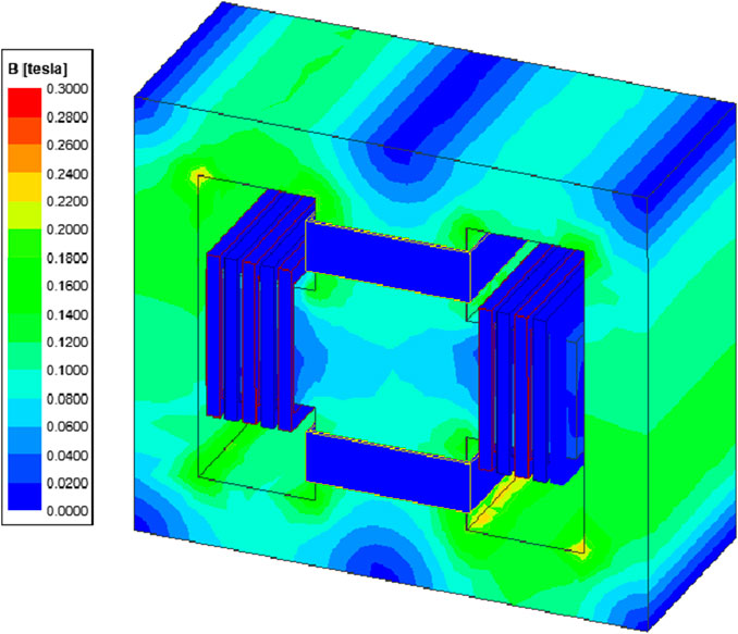
Figure 6. Magnetic flux density distribution of the proposed magnetic integrated structure.
Figure 7 illustrates the intensity of the magnetic field in the space around the transformer when the transformer windings are wound differently. It can be seen that cross-winding can dramatically reduce the intensity of the magnetic field in the space around the windings, which is conducive to reducing electromagnetic interference and eddy current losses caused by leakage flux.
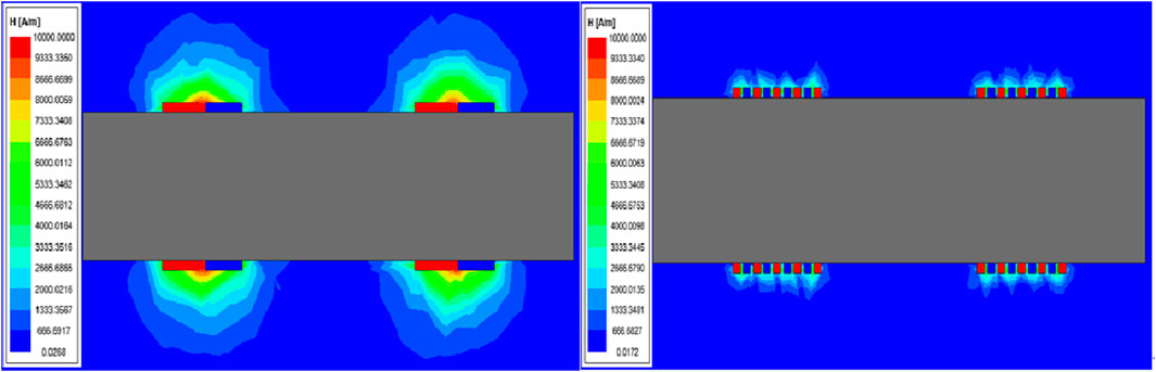
Figure 7. Space magnetic field distribution.
The coupling between the windings has been simulated and shown in Table 3. W11, W21, W12, W22 and W3, W4 are the two transformers’ high- and low-voltage windings and the two resonant inductance windings, respectively. Table 3 shows that there is approximate decoupling between the resonant inductances and the transformers, which is consistent with the results derived in Section 2.
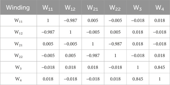
Table 3. Coupling coefficient between windings.
A 400W experimental platform consisting of two LLC resonant converters with IPOP connections has been built to verify the correctness of the double B-type magnetic integrated transformer design, as shown in Figure 8. The system consists of the oscilloscope, DC power supply, STM32, IPOP two LLC resonant converters module, and load resistances, with the parameters shown in Table 4, and the core uses the double B type and EE type. Measurements yielded the EE-type magnetic integrated transformer volume of 43.32cm3 and the double B-type magnetic integrated transformer of 40.76cm3. Although the resonant inductance of the double B-type magnetic integrated transformer is independently wound on the core, the overall volume is still reduced by 5.9% compared to the EE-type core, with an air gap in place of the resonant inductance, which improves the power density while reducing the leakage flux.
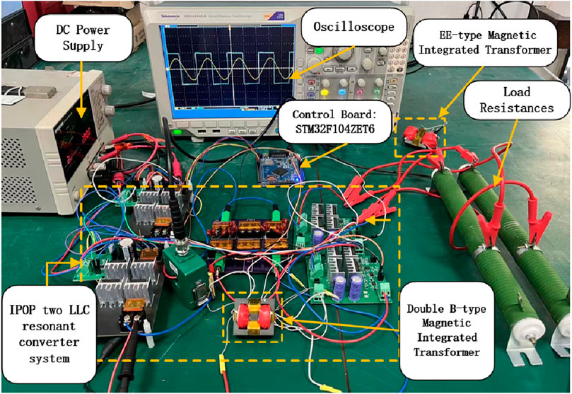
Figure 8. IPOP two LLC resonant converter experimental system.
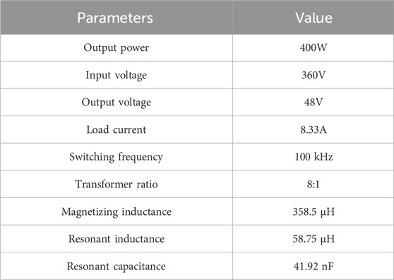
Table 4. Experimental system parameters.
The two types of LLC resonant converters have been tested under full load. The experimental waveforms are shown in Figure 9. VAB is the primary-side full-bridge voltage, and ILr is the peak resonant current. The comparison of the experimental waveforms of the two transformers shows that the double B-type magnetic integrated transformer can work properly, and the resonant current is smaller than the EE-type magnetic integrated transformer. The resonant current reduction can reduce the losses, which verifies the effectiveness of the design.
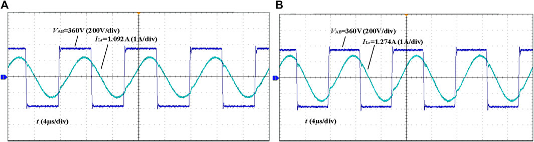
Figure 9. The resonant current and primary side voltage waveforms. (A) Double B-type Magnetic Integrated Transformer (B) EE type Magnetic Integrated Transformer.
The efficiency curves derived from the two transformers measured under the same conditions are shown in Figure 10. The efficiency of the double B-type magnetic integrated transformer is maximally improved by 0.7% over the EE-type magnetic integrated transformer, up to 96%.
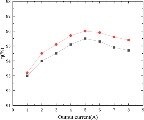
Figure 10. Efficiency curve.
This article proposes a double B-type magnetic integrated structure that can integrate two transformers and two resonant inductances simultaneously. Four magnetic components are placed on four core columns in the middle of the core, which improves the power density while maintaining a uniform flux distribution. The decoupling integration between different components is realized through the design so that each component can operate regularly after integration. The resonant inductance wounded independently simplifies the design of the transformer core while reducing the leakage flux, and the cross-winding of the transformer’s high- and low-voltage windings further reduces the external radiated magnetic field, significantly minimizing electromagnetic interference and eddy current loss. A transformer prototype is built, and the volume of the proposed structure is reduced by 5.9% compared to the EE-type transformer. The experimental results show that the system efficiency can be improved by 0.7% with a transmission power of 400W.
The original contributions presented in the study are included in the article/Supplementary material, further inquiries can be directed to the corresponding author.
NX: Writing–original draft, Writing–review and editing. SY: Writing–original draft, Writing–review and editing. HM: Writing–original draft. XM: Writing–original draft. MC: Writing–original draft.
The author(s) declare that financial support was received for the research, authorship, and/or publication of this article. This paper is supported by The Shanghai Natural Science Foundation, 23ZR1424800.
The authors declare that the research was conducted in the absence of any commercial or financial relationships that could be construed as a potential conflict of interest.
All claims expressed in this article are solely those of the authors and do not necessarily represent those of their affiliated organizations, or those of the publisher, the editors and the reviewers. Any product that may be evaluated in this article, or claim that may be made by its manufacturer, is not guaranteed or endorsed by the publisher.
Ahmad, U., Cha, H., and Naseem, N. (2021). Integrated current balancing transformer based input-parallel output-parallel LLC resonant converter modules. IEEE Trans. Power Electron. 36, 5278–5289. doi:10.1109/TPEL.2020.3026929
Ansari, S. A., Davidson, J. N., and Foster, M. P. (2022). Fully-integrated solid shunt planar transformer for LLC resonant converters. IEEE Open J. Power Electron. 3, 26–35. doi:10.1109/OJPEL.2021.3137016
Bughneda, A., Salem, M., Alhuyi Nazari, M., Ishak, D., Kamarol, M., and Alatai, S. (2022). Resonant power converters for renewable energy applications: a comprehensive review. Front. Energy Res. 10, 846067. doi:10.3389/fenrg.2022.846067
Chen, X., Xu, G., Shen, Q., Sun, Y., and Su, M. (2022). Magnetizing and leakage inductance integration for split transformers with standard UI cores. IEEE Trans. Power Electron. 37, 12980–12985. doi:10.1109/TPEL.2022.3180359
Gao, S., and Wang, H. (2020). A new approach integrated magnetics double-frequency DC/DC converter. IEEE Access 8, 148301–148314. doi:10.1109/ACCESS.2020.3013897
Gao, S., and Zhao, Z. (2021). Magnetic integrated LLC resonant converter based on independent inductance winding. IEEE Access 9, 660–672. doi:10.1109/ACCESS.2020.3046616
Guan, Y., Chang, L., Wang, Y., Wang, W., and Xu, D. (2021). Analytical derivation and design of 20-MHz DC–DC soft-switching resonant converter. IEEE Trans. Industrial Electron. 68, 210–221. doi:10.1109/TIE.2020.2965508
Ievgen, V., Mykola, L., Kawsar, N., Bohdan, P., Oleksandr, H., and Ryszard Michał, S. (2022). Power converter solutions for industrial PV applications-A review. Energies 15, 3295. doi:10.3390/en15093295
Kimura, S., Itoh, Y., Martinez, W., Yamamoto, M., and Imaoka, J. (2016). Downsizing effects of integrated magnetic components in high power density DC–DC converters for EV and HEV applications. IEEE Trans. Industry Appl. 52, 3294–3305. doi:10.1109/TIA.2016.2539920
Li, F., Wang, L., and Yu, L. (2022). A novel integrated matrix magnetics for isolated single-stage DC–DC converter. IEEE Trans. Power Electron. 37, 12380–12390. doi:10.1109/TPEL.2022.3170553
Li, G., Jin, X., Wang, K., Deng, Y., He, X., and Wang, Y. (2019). Hybrid modulation of parallel-series $LLC$ resonant converter and phase shift full-bridge converter for a dual-output DC–DC converter. IEEE J. Emerg. Sel. Top. Power Electron. 7, 833–842. doi:10.1109/JESTPE.2019.2900700
Li, X., Lin, P., and Tang, Yi (2018). Magnetic integration of LTL filter with two LC-traps for grid-connected power converters. IEEE J. Emerg. Sel. Top. Power Electron. 6, 1434–1446. doi:10.1109/JESTPE.2017.2764060
Liu, Y., Wu, H., Ni, S., Song, Y., and Fan, Y. (2023). Lower-height-oriented magnetic integration design for onboard power converter of electric vehicles. IEEE Trans. Transp. Electrification, 1. doi:10.1109/TTE.2023.3259148
Mostafa, N., Shirakawa, T., Kazuhiro, U., Jun, I., Yamamoto, M., and Eiji, H. (2020). Effects of secondary leakage inductance on the LLC resonant converter. IEEE Trans. Power Electron. 35, 835–852. doi:10.1109/TPEL.2019.2911093
Noah, M., Shirakawa, T., Umetani, K., Imaoka, J., Yamamoto, M., and Hiraki, E. (2019a). “Effects of secondary leakage inductance on the LLC resonant converter - part i: transformer voltage gain and efficiency(Conference Paper),” in Conference Proceedings - IEEE Applied Power Electronics Conference and Exposition - APEC. (2019), Anaheim, California, USA, 17-21 March 2019, 780–786. doi:10.1109/APEC.2019.8721980
Noah, M., Shirakawa, T., Umetani, K., Imaoka, J., Yamamoto, M., and Hiraki, E. (2019b). “Effects of secondary leakage inductance on the LLC resonant converter - Part II: frequency control bandwidth with respect to load variation(Conference Paper),” in Conference Proceedings - IEEE Applied Power Electronics Conference and Exposition - APEC. (2019), Anaheim, California, USA, 17-21 March 2019, 1408–1414. doi:10.1109/APEC.2019.8722190
Park, C.-W., and Han, S.-K. (2021). Analysis and design of an integrated magnetics planar transformer for high power density LLC resonant converter. IEEE Access 9, 157499–157511. doi:10.1109/ACCESS.2021.3125262
Vijayakumar, S., and Sudhakar, N. (2022). A review on unidirectional converters for on-board chargers in electric vehicle. Front. Energy Res. 10, 1011681. doi:10.3389/fenrg.2022.1011681
Yang, J., Wu, X., Muhammad, F., and Deng, Z. (2022). External magnetic field minimization for the integrated magnetics in series resonant converter. IEEE Trans. Power Electron. 37, 498–508. doi:10.1109/TPEL.2021.3095491
Yang, Y., Wu, Y., Sun, X., Guo, Ci, and Tian, H. (2021). Design of U+U type magnetic integrated transformer in interlaced bidirectional CLLC resonant converter. Trans. China Electrotech. Soc. 36, 282–291. doi:10.19595/j.cnki.1000-6753.tces.191629
Zeng, J., Zhang, G., Samson, S., Zhang, Bo, and Zhang, Y. (2020). LLC resonant converter topologies and industrial applications — a review. Chin. J. Electr. Eng. 6, 73–84. doi:10.23919/cjee.2020.000021
Keywords: LLC resonant converter, magnetic integration, high power density, high frequency, independent inductance winding
Citation: Xia N, Yan S, Ma H, Mao X and Chen M (2024) Double B-type magnetic integrated transformer based input-parallel output-parallel LLC resonant converter modules. Front. Energy Res. 12:1343247. doi: 10.3389/fenrg.2024.1343247
Received: 23 November 2023; Accepted: 24 January 2024;
Published: 22 February 2024.
Edited by:
Raul Gregor, Universidad Nacional de Asunción, ParaguayReviewed by:
Bin Duan, Shandong University, ChinaCopyright © 2024 Xia, Yan, Ma, Mao and Chen. This is an open-access article distributed under the terms of the Creative Commons Attribution License (CC BY). The use, distribution or reproduction in other forums is permitted, provided the original author(s) and the copyright owner(s) are credited and that the original publication in this journal is cited, in accordance with accepted academic practice. No use, distribution or reproduction is permitted which does not comply with these terms.
*Correspondence: Nenghong Xia, eGlhX25oQHNoaWVwLmVkdS5jbg==
Disclaimer: All claims expressed in this article are solely those of the authors and do not necessarily represent those of their affiliated organizations, or those of the publisher, the editors and the reviewers. Any product that may be evaluated in this article or claim that may be made by its manufacturer is not guaranteed or endorsed by the publisher.
Research integrity at Frontiers
Learn more about the work of our research integrity team to safeguard the quality of each article we publish.