 Guowei Guo1
 Jinfeng Wang
 Zhu Liu
 Aihong Tang
 Yufei Shang
95% of researchers rate our articles as excellent or good
Learn more about the work of our research integrity team to safeguard the quality of each article we publish.
Find out more
ORIGINAL RESEARCH article
Front. Energy Res. , 03 April 2024
Sec. Smart Grids
Volume 12 - 2024 | https://doi.org/10.3389/fenrg.2024.1337649
Disturbances to the power system may lead to relative swing between synchronous generator rotors, causing low-frequency oscillation problems in the absence of damping. In this article, based on the single-machine infinity system containing flexible distribution transformer and synchronous generator, the linearized state equations of the system is deduced by the small-signal modeling. The mechanism of flexible distribution transformer on the rotor speed of synchronous generator is analyzed. The influence factors of flexible distribution transformer on the rotor speed of synchronous generator are analyzed. The equation of the additional damping provided by the flexible distribution transformer to this system is constructed. It was concluded that by controlling the output voltage of the regulating converter in the flexible distribution transformer, the rotor speed of the synchronous generator can be varied to increase the system damping. An additional damping control strategy for flexible distribution transformer is proposed. The simulation verifies that the proposed control strategy can effectively suppress the oscillation amplitude of each electrical quantity and shorten the oscillation duration when the system is subjected to large and small perturbations. The proposed additional damping control strategy of flexible distribution transformer can effectively improve the damping of the system and alleviate the problem of low frequency oscillation.
With the increasing proportion of new energy such as wind power and photovoltaic in the power grid, the structure and operational characteristics of the power system have changed significantly. A large number of power electronic power sources replace the original synchronous generator, resulting in the gradual reduction of rotary mechanical inertia and frequency damping effect provided by the rotor, and the new power system presents low inertia characteristics. Furthermore, the system with low inertia is prone to continuous oscillation after being disturbed, which leads to low frequency oscillation, and seriously affects the safe and stable operation of power system (Zhang et al., 2019; Wang et al., 2022; Wang et al., 2023).
Combined with high reliability of traditional distribution transformers and flexible regulation of voltage source converters, flexible distribution transformer (FDT) can realize voltage regulation, reactive power compensation, harmonic suppression and other functions with smaller capacity voltage source converters in order to meet many regulation requirements in different scenarios of power systems (Tang et al., 2021; Tang et al., 2022a; Tang et al., 2022b; Tang et al., 2024). The power electronic converter in the hybrid power transformer can be selected as AC/DC converter, AC/AC converter, AC/DC/AC back-to-back converter, etc. In the case of high voltage occasions, cascaded or modular converter structure can be selected, and when it comes to high current occasions, based on the current level of development of the power electronics, the power can be enhanced by the parallel connection of multiple sets of converter units to enhance the power and transmission capacity of the output current (Liang et al., 2019; Yang et al., 2022; Zheng et al., 2022).
In order to guarantee the operational reliability and stability of FDT, scholars at home and abroad have conducted in-depth research on its topology and control strategy. The topology of the voltage source converter in the FDT can be selected depending on the application and functional requirements. The scientific reference (Li et al., 2021) suggests a diode-clamped three-level power electronic hybrid transformer topology for power management in medium and high voltage distribution networks, which has advantages in voltage withstanding level and harmonic elimination compared to the conventional two-level inverter. In the reference (Deng et al., 2019), two-stage matrix converters are used in flexible power transformers and predictive control strategies are proposed for this topology, which allows the flexible power transformer to compensate for voltage amplitude peaks and troughs as well as voltage phase angle variations during transmission of power. Reference (Firouzi et al., 2010) proposes a topology that combines a bridge fault current limiter and a power converter. Although this device also improves power quality, unlike FDTs, this topology employs a diode bridge circuit and has less regulation flexibility than FDTs. The control method of the voltage source converter also affects the performance of the system and the regulation function of FDTs. Reference (Zhang et al., 2010; Harnefors et al., 2022; Xiao et al., 2024) describes a constructive network type control strategy for voltage source converters, which simulates the internal synchronisation mechanism of the AC system and avoids the control instability problem caused by the conventional phase-locked loops in weak grids. In the reference (Li et al., 2019), a combination of a fuzzy controller and a traditional PI controller is proposed as a robust fuzzy control strategy for FDT, but the fuzzy control is prone to cause small-scale oscillations near the operating point. Aiming at the problems of voltage swell/sag and frequency fluctuation in the power system. Reference (Zhang et al., 2022) proposes a hybrid distribution transformer with local and remote cooperative control that can solve the problem of voltage fluctuation and load distortion. Comprehensive analysis of the above, the existing FDT control strategies mostly focus on power system voltage oscillation, frequency fluctuation, harmonic control and improving the robustness of the controller. However, few studies have been carried out on FDT damping control strategy for the problem of low-frequency oscillations in power systems. As a consequence, it is urgent to carry out relevant research to provide an effective control scheme for the safe and stable operation of power system.
Aiming at the problem of low frequency oscillation in the new power system with high power electronization, a lot of researches have been carried out on the suppression measures of low frequency oscillation. Reference (Wang et al., 2023) analyzes the damping mechanism of distributed power flow controller on the system, proposes the damping control strategy of distributed power flow controller, and uses artificial fish swarm algorithm to solve the optimal parameters of the damping controller. In Reference (Li et al., 2022), considering the grid-connected and isolated operation modes respectively, a new phase feedforward damping controller is used to replace the traditional frequency deviation feedback path, and a new phase feedforward damping virtual synchronous generator control method is proposed. In reference (Li et al., 2022), a feedback control loop with time delay is established, a new DC voltage feedback active damping control method is proposed, and an oversampling method is proposed to reduce the digital control delay time and improve the damping current accuracy. In the reference (Guo et al., 2023), in order to suppress the low-frequency oscillations of a modular multilevel converter-based high-voltage direct current transmission system (MMC) under low-inertia conditions, a detailed small-signal model considering the dynamics of both the MMC and the synchronous generator is developed, a complementary damping control method is proposed, and the parameters of the method are tuned by using a pole assignment method. However, the above control strategies are more complex, need to adjust more parameters, and there are weak robustness problems. Therefore, an FDT damping control strategy is proposed in this paper, which can always provide fixed damping to the power system with fewer parameters to be adjusted. Moreover, when FDT is applied to suppress the low-frequency oscillation instability of the system, it can not only improve the system damping and solve the low-frequency oscillation problem through the proposed control strategy, but also realize various flexible control functions to improve the power quality of the system (Perez et al., 2021; Xiao et al., 2023).
In this paper, small signal model method is used to analyze the damping characteristics of FDT in order to study the mechanism of FDT suppressing low frequency oscillation in medium and high voltage distribution system. The additional torque and constraint regulation provided by the flexible distribution transformer to the single-machine infinite bus system are derived, and the additional damping control strategy of FDT is proposed. Through the regulation function of the FDT damping controller, the system damping can be effectively improved and the low-frequency oscillation caused by the disturbance can be suppressed.
The FDT is composed of three components: the main transformer, the energy taking converter, and the regulating converter. And the topology is demonstrated in Figure 1.
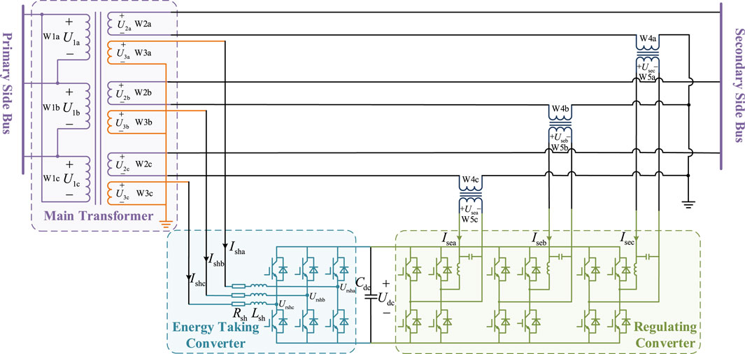
Figure 1. The FDT topology.
The primary transformer is a traditional three-phase, three-winding distribution transformer responsible for the transmission of power and voltage level conversion. The voltages of primary side windings
In order to analyze the damping characteristics of the FDT, a single-machine infinite-bus system with a FDT and a synchronous generator is constructed as shown in Figure 2. The system consists of synchronous generators, step-up transformers, transmission lines, FDT, and an infinite power supply. Consider the main transformer and the isolation transformer as ideal transformers, without regard for the power electronic switching losses in the energy taking converter and regulating converter. In Figure 2,
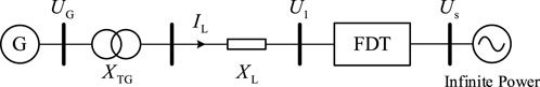
Figure 2. Single machine infinity system with FDT and synchronous generator.
A third order classical model is used for the synchronous generator in a single machine infinity system as shown in Figure 2. In order to simplify the order of the differential equations of the synchronous generator, assuming that the excitation potential and mechanical power of the synchronous generator remain constant, and ignoring the stator winding resistance of the synchronous generator, the rotor motion equation of the synchronous generator in the d-q rotor rotating coordinate system is
where
In the d-q rotor rotating coordinate system, the electrical circuit equation of the synchronous generator is
where
The d0-q0 synchronous rotating coordinate system is established using
where
The electrical quantity of the d0-q0 synchronous rotating coordinate system is converted to the d-q rotor rotating coordinate system by using the coordinate transformation matrix. The coordinate transformation matrix is shown as (Eq. 4)
By left-multiplying (Eq. 4) by (Eq. 3) and combining (Eq. 2), the expression of the output current of the synchronous generator in the d-q rotor rotating coordinate system is obtained as follows:
where
From (Eqs. 1, 2, 5), it can be seen that the state equation of single machine infinite bus system with FDT is a nonlinear equation. In order to linearize the state equation of the system, the perturbation method will be used to solve the small signal model of the state equation of the system.
Assuming that the internal state variable of the single machine infinite bus system with FDT is
From (Eq. 6), the output voltage of the regulating converter is 0 in steady state, then there is
where the subscript 0 denotes the value of each variable in the steady state, same as below.
Substituting (Eq. 7) into Eqs 1, 5, the following equations can be obtained
Assuming that the small perturbations of the state variable and the input variable are
From (Eq. 7) and (Eq. 9), it can be obtained that the state variables and input variables are as shown in (Eq. 10) when considering the presence of small perturbations
The equation of the output current of the synchronous generator in the presence of small disturbances can be deduced as following
Substituting (Eq. 8) into (Eq. 11), the small disturbance
Substituting (Eqs. 10, 11) into (Eq. 1), the expression of the state equation in the presence of small disturbances is acquired:
By combining (Eqs. 12, 13), the small signal model of the state equation of the single machine infinite bus system with FDT can be deduced as:
where
In (Eq. 14),
Based on the above analysis, by controlling the output voltage 1 and 2 of the regulating converter in the FDT, 4,5 and 6 of the state variables of the synchronous generator can be changed, so that the FDT has a certain damping effect on the power system.
Based on the analysis of the damping characteristics of FDT in Section 1, this paper proposes an additional damping control strategy for FDT. The energy taking converter and regulating converter perform a regulatory function in the FDT, and the two devices have distinct roles within the additional damping control strategy. The energy taking converter draws active power from the system to sustain the stability of the DC capacitor voltage. Additionally, the regulating converter serves as the primary controlling device for the additional damping control. Through controlling the output voltage, the regulating converter offers supplementary damping for the power system, enhancing the system’s transient stability, and affecting the rotor speed of the synchronous generator.
The following specific analysis of the additional damping control effect of the regulating converter in the FDT on the power system. The motion equation of synchronous generator rotor speed
In Equation 16,
From the above analysis, the extra torque provided by the FDT to the single machine infinite bus system can be defined as follows
To ensure that the extra torque supplied by the FDT to this single machine infinity system always maintains a positive damping effect on the rotor speed of the synchronous generator, the additional torque of the FDT should satisfy the following constraints
where
Assuming that the transfer functions of the d-axis component
Substituting (Eq. 19) into (Eq. 17), the equation for the additional damping provided by the FDT to this single infinity system is obtained as
From (Eq. 20), it is only necessary to ensure that transfer function
where
Therefore, the damping control strategy of FDT is obtained as follows
From Equation 22, it can be seen that the additional damping is affected by the gain
Combining the above analyses, the additional damping control strategy of the FDT proposed in this paper is as follows: (i) The rotor electrical angle
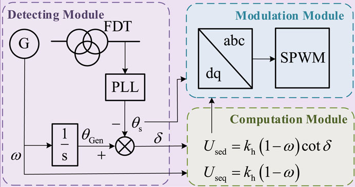
Figure 3. Block diagram of additional damping control strategy for flexible distribution transformer.
The control strategy of the energy taking converter is analysed below. From Figure 1, the loop equations of the energy taking converter in the d0-q0 synchronous rotation coordinate system can be obtained as follows
where
The Laplace transform of (Eq. 23) yields the transfer functions of
From (Eq. 24), it can be seen that there is a coupling relationship between the d-axis component and the q-axis component of the output current, so the feed-forward decoupling control method is used. If the controller is a PI controller, the current inner-loop control strategy of the energy taking converter is
where
In order to maintain the stability of the DC capacitor voltage, the outer loop control strategy of the energy taking converter is shown in Equation 26. When there is no additional control requirement, the q-axis component of the output current of the energy taking converter is usually set to 0, so there is
where
In summary, (Eqs. 25, 26) are used as the inner-loop and outer-loop control strategies of the energy taking converter respectively, to form a block diagram of the control strategy of the energy taking converter of the FDT as shown in Figure 4. In Eq. 25, the modulation voltage of SVPWM is obtained by three-phase Park inverse transformation of
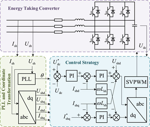
Figure 4. Block diagram of control strategy for FDT energy taking converter.
In order to verify the effectiveness of the proposed additional damping control strategy for FDT, the simulation test system shown in Figure 2 is constructed in the PSCAD/EMTDC software, and the proposed additional damping control strategy for FDT is verified through the three-phase short-circuit fault condition and load surge condition. The main parameters of the simulation test system are shown in Table 1.
(1) Three-phase short-circuit fault condition

Table 1. Main parameter settings of the simulation test system.
The proposed control strategy is verified by simulation under the condition of three-phase short-circuit fault. The simulation settings are as follows: the total duration of the simulation is 10 s. At the moment of 0.3 s the synchronous generator changes from a constant speed operation mode to a rotor free running mode. At the moment of 0.5 s the FDT energy taking converter is put into operation, and at the moment of 0.8 s the FDT regulating converter is put into operation. A three-phase short-circuit ground fault occurs in the line between the primary side of the FDT and the secondary side of the step-up transformer at the moment of 1s, with a fault duration of 0.05 s.
The waveforms of synchronous generator electromagnetic torque, synchronous generator frequency, line active power, and line reactive power after the occurrence of three-phase short-circuit ground fault are shown in Figure 5. It can be seen from the simulation waveform that if there is no additional damping controller for the FDT, the electromagnetic torque of the synchronous generator, the frequency of the synchronous generator and the line power flow will oscillate rapidly after the three-phase short-circuit ground fault occurs. The electromagnetic torque of the synchronous generator is still 1.02 (pu) at 10 s, and the maximum amplitude of the frequency oscillation of the synchronous generator is 50.37 Hz, and the frequency amplitude is still 50.03 Hz at 10 s. If the additional damping controller of the FDT is put into operation, the electromagnetic torque of the synchronous generator, the frequency of the synchronous generator and the oscillation amplitude of the line power flow can be quickly attenuated, and the oscillation duration is about 4.5 s to restore stable operation.
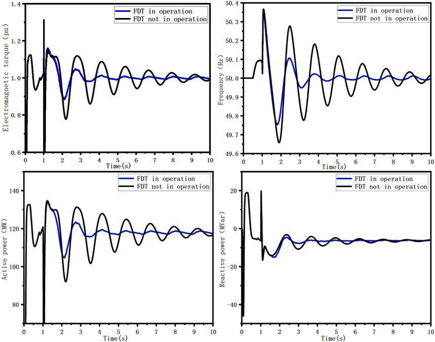
Figure 5. Electromagnetic torque, frequency and line power waveforms of synchronous generator when system disturbance occurs.
The waveforms of the capacitive voltage on the DC side of the FDT and the output voltage of the regulating converter after the occurrence of a three-phase short-circuit ground fault are shown in Figure 6. It can be seen from the simulation waveform that the energy taking converter of the FDT completes the uncontrolled rectification and controllable inverter process during 0.5–1.0 s, so that the DC capacitor voltage is stabilized at the command value of 20 kV. The three-phase short-circuit grounding fault occurs at 1.5 s, and the DC voltage fluctuates about 2.7 s to restore the command value operation. In the additional damping control of the FDT, regulating the output voltage of the regulating converterr can invert the corresponding voltage to provide additional damping for the system during the oscillation process of the system and suppress the low-frequency oscillation of the system.
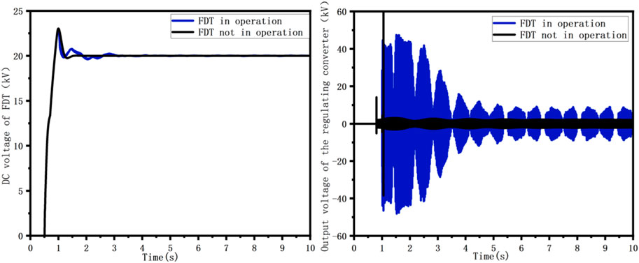
Figure 6. DC voltage of FDT and output voltage waveform of regulating converter when large disturbance occurs in the system.
The above analyses show that when a large disturbance such as a short-circuit fault occurs in the system, the electrical quantity of the system rises abruptly at the instant of the fault. Under the additional damping control of the FDT, the regulating converter can invert the corresponding output voltage for the change of rotor swing angle to provide additional damping for the system, so that the electromagnetic torque, frequency, and line current amplitude of the synchronous generator can be significantly suppressed to significantly shorten the duration of the oscillation of the system after a large disturbance, and the system electrical quantities can be quickly restored to a stable value. Therefore, the proposed additional damping control strategy for FDT has the function of improving the damping of the power system, and can effectively suppress the low-frequency oscillations generated by the system after being perturbed.
(2) Load surge condition
Through the load input system to simulate the occurrence of small disturbances in the system, the simulation settings are as follows: the simulation length of 10 s, 0.2 s time synchronous generator from the constant speed mode of operation into the rotor free operation mode, 0.5 s time flexible distribution transformer energy converter into operation, 0.8 s time FPT control converter into operation, 1.5 s time 150 MW load into the system.
After the load is put into the system, the synchronous generator electromagnetic torque, frequency, output active power, output reactive power waveforms are shown in Figure 7. From the simulation waveforms, it can be seen that if the FPT does not carry out additional damping control, the synchronous generator electromagnetic torque, frequency and power rapidly generate oscillations after the load is put into the system. Among them, the oscillation amplitude of electromagnetic torque is 1.42 (pu) at the moment of 3.2 s, and the oscillation amplitude is still 1.12 (pu) at the moment of 10s. The synchronous generator frequency oscillation amplitude is 50.56 Hz after the load is put into operation, and the oscillation amplitude is still 50.11 Hz at 10 s. If the FPT additional damping controller is put into operation, the electromagnetic torque oscillation amplitude is 1.11 (pu) at 3.2 s, and the duration of the oscillation is about 3 s and then returns to stability. The synchronous generator frequency oscillation amplitude is 50.26 Hz at maximum, and the frequency amplitude remains at 50.01 Hz after the oscillation duration of about 3.5 s.
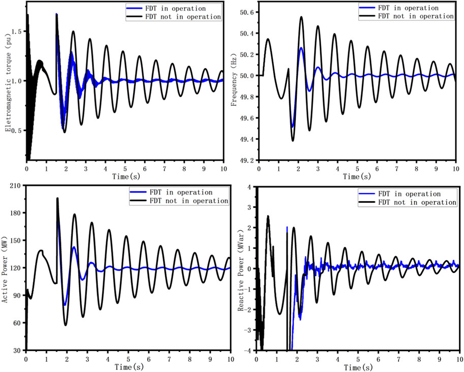
Figure 7. Synchronous generator electromagnetic torque, frequency, line active power and reactive power waveforms after load input occurs.
Comprehensive analysis of the above can be seen, in the flexible distribution transformer additional damping control strategy, the control converter can provide the corresponding additional damping for the system, the synchronous generator electromagnetic torque, frequency, line active power, line reactive power and line voltage oscillation amplitude to the obvious suppression of the oscillation duration is significantly reduced, so the proposed additional damping control strategy of the flexible distribution transformer can effectively improve the system Therefore, the proposed flexible distribution transformer additional damping control strategy can effectively improve the system damping and reduce the low-frequency oscillations generated after the system is subjected to small disturbances.
In this paper, aiming at the problem of low frequency oscillation caused by disturbance, the damping characteristics of FDT are analyzed, and an additional damping control strategy of FDT is proposed. The control strategy is verified by simulation, and the following conclusions are obtained:
(1) In this paper, the linearised equation of state of a single machine infinity system containing a FDT and a synchronous generator is derived based on the small-signal modelling method, and based on this linear equation of state, the influence path of the FDT on the rotor speed of the synchronous generator is analysed. The additional damping provided by the FDT is affected by the gain
(2) In this paper, a FDT additional damping control strategy is proposed, and the simulation results show that, under the effect of additional damping control, the synchronous generator electromagnetic torque and frequency return to stable operation after the system has a three-phase short-circuit ground fault with an oscillation duration of about 4.5 s. After a load surge occurs in the system, the synchronous generator electromagnetic torque and frequency return to stability after about 3 s of oscillation. Therefore, the proposed additional damping control strategy of FDT can invert the corresponding output voltage to the system according to the change of rotor swing angle, provide additional damping for the system on the basis of the inherent damping, effectively reduce the amplitude of the oscillation of various electrical quantities of the system after being disturbed, and reduce the duration of the system oscillation, and improve the transient stability of the power system.
The original contributions presented in the study are included in the article/supplementary material, further inquiries can be directed to the corresponding author.
GG: Writing–original draft, Validation, Supervision, Methodology, Funding acquisition, Conceptualization. JW: Writing–original draft, Validation, Supervision, Methodology, Funding acquisition. XZ: Writing–review and editing, Project administration, Investigation, Funding acquisition, Data curation. ZL: Writing–original draft, Investigation, Funding acquisition, Data curation. DG: Writing–original draft, Funding acquisition, Formal Analysis, Data curation. AT: Writing–review and editing, Writing–original draft, Validation, Supervision, Project administration, Methodology, Investigation, Funding acquisition, Data curation, Conceptualization. YS: Writing–original draft, Validation, Software, Investigation, Data curation. ZW: Writing–original draft, Investigation, Data curation.
The author(s) declare financial support was received for the research, authorship, and/or publication of this article. All authors are grateful to the China Southern Power Grid. The work received funding from the “China Southern Power Grid” through the project “Research on New Distributed Power Flow Control and New Flexible Distribution Transformer Technology” project number is GDKJXM20222475.
This article is grateful to China Southern Power Grid Power Grid Project for funding.
Authors GG and XZ were employed by Foshan Power Supply Bureau of Guangdong Power Grid Co. Author JW was employed by Electric Power Research Institute of Guangdong Power Grid Co. Author ZL was employed by Guangdong Power Grid Co. Author DG was employed by Qingyuan Power Supply Bureau of Guangdong Power Grid Co.
The remaining authors declare that the research was conducted in the absence of any commercial or financial relationships that could be construed as a potential conflict of interest.
The authors declare that this study received funding from the China Southern Power Grid. The funder had the following involvement in the study: methodology, project administration, data collection and analysis, decision to publish.
All claims expressed in this article are solely those of the authors and do not necessarily represent those of their affiliated organizations, or those of the publisher, the editors and the reviewers. Any product that may be evaluated in this article, or claim that may be made by its manufacturer, is not guaranteed or endorsed by the publisher.
Deng, W., Yang, Y., Guo, Y., and Li, L. (2019). Research on predictive control of TSMC hybrid transformer. Power Syst. Prot. Control 47 (11), 71–78. doi:10.19783/j.cnki.pspc.180728
Firouzi, M., B Gharehpetian, G., and Pishvaie, M. (2010). Proposed new structure for fault current limiting and power quality improving functions. Int. Conf. Renew. Energies Power Qual. (ICREPQ’10) 1 (8), 47–52. doi:10.24084/repqj08.216
Guo, C., Xu, L., Yang, S., and Jiang, W. (2023). A supplementary damping control for MMC-HVDC system to mitigate the low-frequency oscillation under low inertia condition. IEEE Trans. Power Deliv. 38 (1), 287–298. doi:10.1109/TPWRD.2022.3186940
Harnefors, L., Schweizer, M., Kukkola, J., Routimo, M., Hinkkanen, M., and Wang, X. (2022). Generic PLL-based grid-forming control. IEEE Trans. Power Electron 37 (2), 1201–1204. doi:10.1109/TPEL.2021.3106045
Li, D., Liang, D., Gao, Y., Zhang, M., Zhang, L., Qi, B., et al. (2019). NIR-II fluorescence imaging of skin avulsion and necrosis. Trans. China Electrotech. Soc. 36 (S2), 696–722. doi:10.3389/fchem.2019.00696
Li, D., Wu, Z., Wang, C., Tang, L., and Liang, D. (2021). Research on topology of a three-level power electronic hybrid transformer. Transformers 58 (10), 41–47. doi:10.19487/j.cnki.1001-8425.2021.10.007
Li, H., Yin, Q., Wang, Q., Luo, H., and Hou, Y. (2022b). A novel DC-link voltage feedback active damping control method for IPMSM drives with small DC-link capacitors. IEEE Trans. Industrial Electron. 69 (3), 2426–2436. doi:10.1109/TIE.2021.3066942
Li, M., Yu, P., Hu, W., Wang, Y., Shu, S., Zhang, Z., et al. (2022a). Phase feedforward damping control method for virtual synchronous generators. IEEE Trans. Power Electron. 37 (8), 9790–9806. doi:10.1109/TPEL.2022.3150950
Liang, D., Liu, Y., Kou, P., Cai, S., Zhou, K., and Zhang, M. (2019). Analysis of development trend of intelligent distribution transformer. Automation Electr. Power Syst. 44 (7), 1–14. doi:10.7500/AEPS20190507007
Perez, M. A., Ceballos, S., Konstantinou, G., Pou, J., and Aguilera, R. P. (2021). Modular multilevel converters: recent achievements and challenges. IEEE Open J. Industrial Electron. Soc. 2, 224–239. doi:10.1109/OJIES.2021.3060791
Tang, A., Ma, L., Qiu, P., Song, J., Chen, Q., Guan, M., et al. (2022a). Research on the harmonic currents rates for the exchanged energy of unified distributed power flow controller. IET Generation, Transm. Distribution 17 (3), 530–538. doi:10.1049/gtd2.12741
Tang, A., Song, X., Shang, Y., Guo, G., Yu, M., and Zhan, X. (2024). Harmonic mitigation method and control strategy of offshore wind power system based on distributed power flow controller. Automation Electr. Power Syst. 48 (2), 20–28. doi:10.7500/AEPS20230113008
Tang, A., Zhai, X., Lu, Z., Zheng, X., and Xu, Q. (2021). A novel topology of distributed power flow controller for distribution network. Trans. China Electrotech. Soc. 36 (16), 3400–3409. doi:10.19595/j.cnki.1000-6753.tces.200744
Tang, A., Zhou, W., Song, J., Qiu, P., Chen, Q., Zhai, X., et al. (2022b). Optimal output power coordinated control strategy of distributed power flow controller. Int. J. Electr. Power and Energy Syst. 140, 108075. doi:10.1016/j.ijepes.2022.108075
Wang, G., Fu, L., Hu, Q., Liu, C., and Ma, Y. (2022). Analysis and control of low frequency oscillation damping of virtual synchronous generator with voltage loop effect. Automation Electr. Power Syst. 46 (14), 177–184. doi:10.7500/AEPS20211112003
Wang, H., Liu, M., Dong, H., Lu, S., Yang, Z., Cheng, S., et al. (2023a). Analysis and suppression of Low Frequency Oscillation in power systems with high proportion of new energy. Electr. Power Autom. Equip. 43 (9), 152–163. doi:10.16081/j.epae.202307020
Wang, J., Tang, A., Guo, G., Lu, Z., Yang, Y., and Zhou, W. (2023b). Research on damping control of distributed power flow controller. Power Syst. Prot. Control 51 (10), 163–171. doi:10.19783/j.cnki.pspc.221383
Xiao, H., Gan, H., Yang, P., Li, L., Li, D., Hao, Q., et al. (2023). Robust submodule fault management in modular multilevel converters with nearest level modulation for uninterrupted power transmission. IEEE Trans. Power Del, 1–16. doi:10.1109/TPWRD.2023.3343693
Xiao, H., He, H., Zhang, L., and Liu, T. (2024). Adaptive grid-synchronization based grid-forming control for voltage source converters. IEEE Trans. Power Syst. 39 (2), 4763–4766. doi:10.1109/TPWRS.2023.3338967
Yang, B., Zhao, J., Ji, Z., Wang, J., and Zhou, K. (2022). Research review of hybrid transformer technology. Electr. Power Autom. Equip. 40 (2), 205–213. doi:10.16081/j.epae.202001034
Zhang, L., Harnefors, L., and Nee, H.-P. (2010). Power-synchronization control of grid-connected voltage-source converters. IEEE Trans. Power Syst. 25 (2), 809–820. doi:10.1109/tpwrs.2009.2032231
Zhang, L., Liu, Y., Liang, D., Kou, P., Wang, Y., Cao, Y., et al. (2022). Local and remote cooperative control of hybrid distribution transformers integrating photovoltaics in active distribution networks. IEEE Trans. Sustain. Energy 13 (4), 2012–2026. doi:10.1109/TSTE.2022.3179120
Zhang, N., Liu, J., Chen, J., Yao, Y., Bao, Y., Chen, P., et al. (2019). Low Frequency Oscillation suppression strategy based on Flexible load and UPFC. Power Syst. Prot. Control 47 (10), 82–87. doi:10.19783/j.cnki.pspc.180748
Zheng, L., Aniruddh, M., Vikram, C., Nishant, B., Rajendra, K., Maryam, S., et al. (2022). Solid-state transformer and hybrid transformer with integrated energy storage in active distribution grids: technical and economic comparison, dispatch, and control. IEEE J. Emerg. Sel. Top. Power Electron. 10 (4), 3771–3787. doi:10.1109/JESTPE.2022.3144361
Keywords: flexible distribution transformer, additional damping control strategy, lowfrequency oscillation, small-signal modeling, voltage source converter
Citation: Guo G, Wang J, Zhan X, Liu Z, Gong D, Tang A, Shang Y and Wang Z (2024) Research on additional damping control strategy of flexible distribution transformer. Front. Energy Res. 12:1337649. doi: 10.3389/fenrg.2024.1337649
Received: 13 November 2023; Accepted: 14 March 2024;
Published: 03 April 2024.
Edited by:
Shuqing Zhang, Tsinghua University, ChinaReviewed by:
Mehdi Firouzi, Islamic Azad University, Abhar, IranCopyright © 2024 Guo, Wang, Zhan, Liu, Gong, Tang, Shang and Wang. This is an open-access article distributed under the terms of the Creative Commons Attribution License (CC BY). The use, distribution or reproduction in other forums is permitted, provided the original author(s) and the copyright owner(s) are credited and that the original publication in this journal is cited, in accordance with accepted academic practice. No use, distribution or reproduction is permitted which does not comply with these terms.
*Correspondence: Aihong Tang, dGFoQHdodXQuZWR1LmNu
Disclaimer: All claims expressed in this article are solely those of the authors and do not necessarily represent those of their affiliated organizations, or those of the publisher, the editors and the reviewers. Any product that may be evaluated in this article or claim that may be made by its manufacturer is not guaranteed or endorsed by the publisher.
Research integrity at Frontiers
Learn more about the work of our research integrity team to safeguard the quality of each article we publish.