- Department of Mechanical Engineering, Thermo-Fluid and Energy Research Group, Obafemi Awolowo University, Ile-Ife, Nigeria
The aim of this study is to investigate the post-injection flow interactive effects of atomized fuel blends from an injector system of known characteristics into a direct injection compression ignition engine combustion chamber and their outcomes. Attempts were made to link the interactive influence of blend mixture quality, effluence and consumption rate of fuel injection properties on frictional loss, heat liberation, combustion, and volumetric efficiency performance outcomes of the engine. This numerical–experimental dimension study began with computational fluid dynamics (CFD) prediction of fuel in-cylinder behavior between a 225° CA (crank angle) (45°ABDC—after bottom dead center) and 360°CA (0° BTDC—before top dead center) compression stroke elapsing into an expansion stroke. A Testo gas analyzer was used to determine the combustion efficiency. The experiments validated the CFD outcomes presented. Willans lines were applied on blends to compare piston frictional losses. A swirl prediction maximum peak of 0.027237 at 336.15 CA for pure diesel blend (D100) at 2,300 rpm and 0.066811 at 341.3 CA for pure biodiesel blend (B100) at 1,800 rpm aided the mixing quality. The instantaneous velocity on the sinusoidal profile and contour around the swirling peak crank angle revealed ignition activity resulting from high mixing quality. The engine possessed high-efficient fuel blends burning strength on a minimum of 54.5% at a higher flow rate. The engine speed and flow rate interaction on the heat liberation rate made a symmetric profile for D100 and B100. Engine energy loss on friction was minimal with D100 compared to B100 and 5% biodiesel to 95% diesel blend (B5).
1 Introduction
Combustion is said to be a complex phenomenon of dependent factors. The internal combustion engine (ICE) system has gained significant research attention. Wysocki et al. (2018) introduced the technology of a mobile test rig on combustion, promoting the mobility of the performance and emission characterization site, even farm-based locations. Endoscope photographing technology in ICE fuel atomization and flame studies was applied by Mao et al. (2020) and Stepien et al. (2022), while the application of AI on pump and engine performance and emission and optimization studies were also presented (Karami et al., 2019; Ude et al., 2020; Onukwuli et al., 2021; Said et al., 2022; Yamin and Hdaib, 2022; Feng et al., 2023). A study on the mass flow rate effect found expression in the thermal management of the battery fuel cell reaction phenomenon (Zuo et al., 2022). This strengthens the band of the electric vehicle clean power system in its use of the proton exchange membrane and its application and optimization in conjunction with hydrogen combustion technology in ICE (Zuo et al., 2023a; Zuo et al., 2023b; Chen et al., 2023; Zuo et al., 2023c).
Specific contributions of fuel combustion studies in engine performance and emission have been on a secondary and tertiary fuel blending ratio for spark ignition (SI) and compression ignition (CI) engines, as presented by Al-Hasan and Al-Momany (2008); Abdullah et al. (2015); Liu H. et al. (2015); Akar (2016); Deng et al. (2018); Mohammed et al. (2021); and Prasad and Saravanan (2021). The ternary fuel blending effect on pump was studied by Caligiuri et al., (2019). Also antioxidant and nanoparticles additives flow enhancement pay tribute to performance (Shahabuddin et al., 2013; Shaafi and Velraj, 2015; Feroskhan et al., 2017; Perumal Venkatesan et al., 2021; Daud et al., 2022; Küçükosman et al., 2022). Meanwhile, fuel spray and atomization, fuel injection timing, and pressure variation are current issues of study in the literature, as presented by Kumar and Rehman (2014); Liu J. et al. (2015); Rai et al. (2021); Sun et al. (2021); Küçükosman et al. (2022); Pham et al. (2022); and Stępień et al. (2022). The technique of dual-fuel engine mode with little or no adjustment of the engine system was studied by Feroskhan et al. (2017); Mahla et al. (2017); Ambarita, (2018); Parthasarathy et al. (2019); Estrada et al. (2022); and Jamrozik et al. (2022). To date, dual-fuel injection and combustion studies have focused on the gas fuel flow rate and mixing techniques of homogeneous charge compression ignition (HCCI) technology (Kumar and Rehman, 2014; Gnanamoorthi and Vimalananth, 2020; Atelge et al., 2022; Park et al., 2022; Zardoya et al., 2022). All these studies target the manipulation of fluid flow or its properties for investigating the effect on engine combustion and performance. Another significant addition to the aforementioned study is the impact of the flow rate either prior to or within the combustion chamber. Major works done so far focus on the variation in either fuel flow or air flow rates of various fuels accompanied with the blending effect on SI and CI engines. Mahla et al. (2017) and Parthasarathy et al. (2019) investigated the effect of compressed natural gas (CNG) flow rate variation on CI engine performance, while biogas and hydrogen flow rate variations were studied by others (Feroskhan et al., 2017; Ambarita, 2018; Estrada et al., 2022). Majority of the works focused on the flow rate, existing in the dual-fuel engine mode (Feroskhan et al., 2017; Mahla et al., 2017; Ambarita, 2018; Parthasarathy et al., 2019; Estrada et al., 2022) instead of the usual single-engine operation mode. In this regard, Jamrozik et al. (2022) stated the difference between the effect of both modes, i.e., the flame front will usually form around the injected stream and spread to the filled areas with a single engine; however, the limitations of fuel type will hinder this spread in a dual-fuel engine. Gnanamoorthi and Vimalananth (2020) concluded that the heat release rate (HRR), cylinder pressure, and NOx increased by 28.66%, 28.9%, and 7.3%, respectively, under 30 L/min of hydrogen fuel at brake power variation. A microscopic spray investigation discussed the effect of fuel physical properties and control parameters on atomization and submitted that the spray angle and droplet velocity depend on fuel viscosity (Sun et al., 2021). In another study, the effects of the spray droplet, ambient air mixing, and gas flow rate of a dual-fuel engine brake-specific fuel consumption (BSFC), in-cylinder pressure, and heat release rate improve, while brake thermal efficiency (BTE) and brake volumetric efficiency (BVE) generally remain lower compared to that when using traditional diesel (Pham et al., 2022). Furthermore, in a mixing study, the combination of an early pilot and a large squish piston geometrical approach on a natural gas–diesel dual-fuel engine was investigated using a double injection mode on engine BTE and emission. An improvement of 7.8% and 49.7% in BTE and methane emission, respectively, was obtained, which was better than that obtained with the single injection of pilot dual fuel (Park et al., 2022).
In-cylinder piston frictional mean effective pressure (FMEP) in ICE losses has been said to exist due to the collection of sub-frictional loses; mechanical mean effective pressure (MMEP) is applied to surmount mechanical friction; power-gaining mean effective pressure (PMEP) exists only in four-stroke engines; charging mean effective pressure (CMEP) is used in driving a supercharger or scavenging pump; turbine-added mean effective pressure (TMEP), turbine add-on pressure, and auxiliary-driving mean effective pressure (AMEP) are usually added with brake mean effective pressure (BMEP), thus yielding indicated mean effective pressure (IMEP) (Taylor, 1985b). Amid rundown, shutoff, Willans lines, motoring, strip, indicated and special measuring known methods of friction determination, according to Van Basshuysen and Schäfer (2004), the indicated method was applied in an experimental and simulation study of FMEP determination in a four-cylinder CI engine (Knauder et al., 2019). A similar study was executed numerically in a four-stroke four-cylinder SI engine, validating existing work (Mishra, 2013). The work suggested that an experimented frictional study by reason of higher boundary friction yields larger friction than the predicted friction. Second, frictional force is maximum within compression and power strokes and negligible in suction and exhaust strokes. Feng et al. (2022) presented a comparative study on energy balance on an automated and manual transmission hybrid vehicle to account for energy losses.
Researchers have also focused on the experimental and numerical dimensions of ICE flow. Increasing diesel and air flow rates in flame stability, combustion efficiency, and other parameters increased the combustion flame instability and efficiency (Li et al., 2022). An engine was studied as a two-phase flow-accommodating entity for heat and fluid flow in CFD studies of velocity magnitude, penetration length, swirl and tumble ratios, and heat release rate, and an experimented heat flow characteristic in blends of 100% pure Khaya senegalensis biodiesel blend (B100), B20, and pure diesel blend (D100) of Jatropha biodiesel (Atgur et al., 2022). A significant difference between B20 and D100 within compression and expansion strokes under a no-load condition was reported. A CFD energy analysis of B100 and D100 was done on combustion heat transfer, inlet, and exhaust flow properties using MATLAB by Potdukhe and Deshmukh, (2015), while a particulate filter on boundary-layer wall flow with biofuel was reported (Orihuela et al., 2019). Numerical studies have been conducted to investigate the influence of piston-bowl geometrical design (Deresso et al., 2022) on the HRR of engine performance, while others calculate the HRR with experimental validation (Mauro et al., 2018; Dubov et al., 2021). The application of a control system to the blending process of fuel and corrosion inhibitor additive blends on a direct injector system was modeled to ensure a stable blending process despite flow velocity perturbation (Mgbemene et al., 2019).
It is necessary to understand how the injected fuel blend characteristics and in-cylinder conditions influence engine combustion outcomes. Hence, this study presents the impact of injector and piston engine elements on the interaction between in-cylinder fluid motion and the combustion chamber environment with respect to the flow effects on engine combustion strength. Attempts to numerically link the effect of fuel blend atomization and mixing strength on the expected performance index were key in this study with experimental validations. The scope of this work majors between compression and power strokes of a single-cylinder CI engine. As was found from the reviewed literature, studies on the fuel flow rate have focused on air and gaseous fuel flows in single- and dual-fuel engines; therefore, this study focused on the liquid fuel flow rate combustion of a homogenous fuel engine.
2 Materials and methods
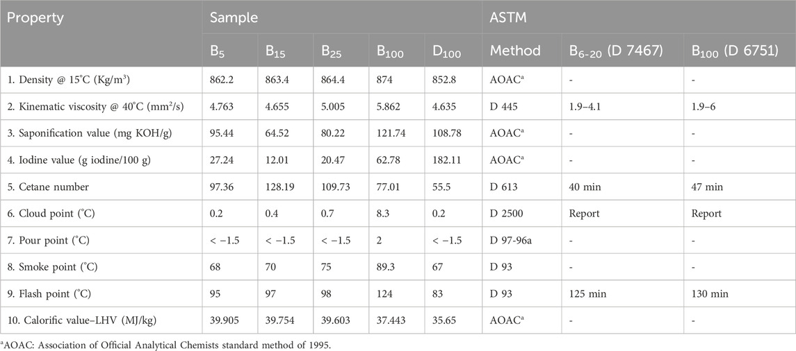
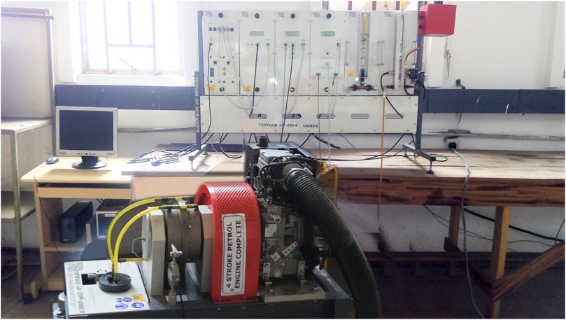
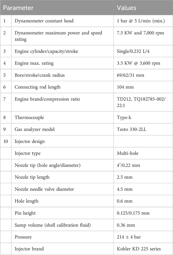
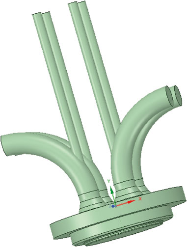
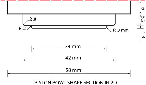
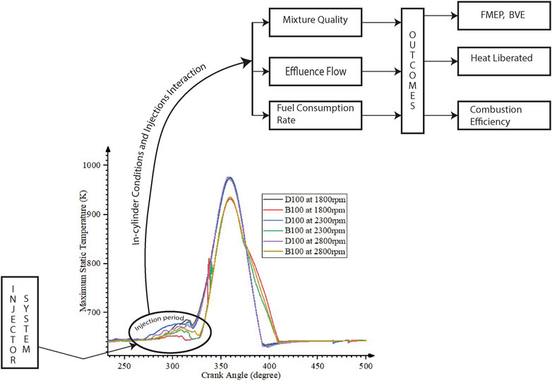
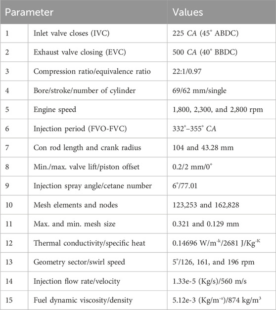
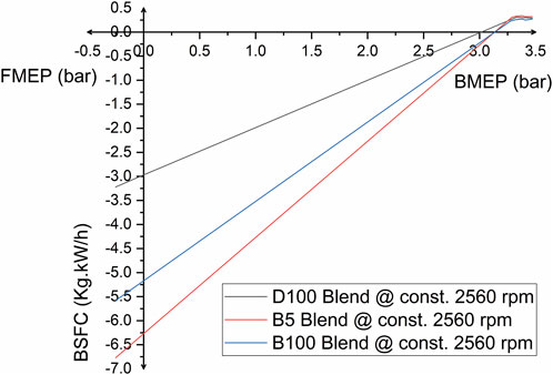
The physicochemical properties of Khaya senegalensis biodiesel blends of 5% of biodiesel to 95% of diesel blend (B5), 15% of biodiesel to 85% of diesel blend (B15), 25% of biodiesel to 75% of diesel blend (B25), B100, and D100 produced experimentally by Onojowho et al. (2019) are given in Table 1. These binary blends are a percentage volumetric proportion of biodiesel and diesel mixed at a stirring speed of 1.5 using the IKA C-MAG HS 4 for 7 min. Before allowing each sample to stand, the TecQuipment Ltd. small engine test rig fitted with a hydraulic dynamometer, as shown in Figure 1 with specifications in Table 2, was applied for the experiment. Each sample was poured into the engine tank, taking turns to flow through the FLOWave SAW flowmeter type 8098. The conical geometry injector fitted into the engine is a multi-hole swirl injection system, design parameters of which are given in Table 2, and generated a swirl on the piston bowl. Combustion efficiency was determined from flue gases using a gas analyzer. By experimentation, the Willans line approach was applied to determine the least piston frictional loss from three selected blends as the FMEP outcome, as shown in Figure 4, at a constant rate of 2,560 rpm. Its low initialization temperature of 300 K was reflected in the combustion temperature. Ansys Fluent v19.R3 software was used to simulate the combustion, and the engine and biodiesel parameters are summarized in Table 3. The HP Z820 Workstation system model was used in this simulation. The engine geometry model was produced on Ansys SpaceClaim having a piston bowl shape and four manifolds, as shown in Figure 2, which was later decomposed to a sector. Figure 3 presents a 2D piston bowl-shaped engine model. The decomposed geometry was meshed into a tri/tetrahedron element-shape type of mesh, and the fine mesh size and total element numbers are shown in Table 3. Deforming the zone mesh sensitivities by applying smoothing and layering mesh methods of the dynamic mesh ensured accuracies. High computational timing was traded-off for accuracy since the total number of elements increases with transition from coarse to fine mesh types. The entire simulation was between the inlet valve closes (IVC) and exhaust valve closing (EVC); however, the compression stroke period of the IVC (225° crank angle [CA] or 45° after bottom dead center [ABDC]) to the fuel valve closes (FVC) (360° CA or 0° before top dead center [BTDC]) of the fuel injection and mixture interaction within the in-cylinder environment is shown in Figure 4. Here, the static temperature is the temperature indicated by the sensor moving concurrently with the mixture velocity. The profile predicted the possible point at which each blend pitches the maximum temperature. A distinct observation was made with each blend with the in-cylinder temperature, indicating that blending viscosity, surface tension, and density together with the velocity, pressure, and temperature generates swirl, tumble, and turbulence, significantly contributing to combustion. During the injection period, the profile made by blends suggested the distinct swirl influence of each blend on the engine performance as the engine speed increases. The injection pressure is directly proportional to the engine speed square, and it is a vital response factor in atomization such that the higher the pressure, the better the atomization but not beyond a threshold of creating penetration issues (Taylor, 1985a). In this regard, this simulation considers the injection pressure, angle, velocity, timing, angle, and nozzle diameter to be constant, while the aforementioned blend characteristics with engine speed were varied. The injection diameter at the chamber inlet was 0.00185 m, and the temperature boundary conditions of the walls are as follows: piston, 645 K; valve and chamber, 562 K; and cylinder head, 604 K. Temperature and pressure variable conditions at fluid–wall patched zones were maintained at 404 K and 321,259 Pa, respectively.
2.1 Fundamental models and equations
The renormalized group (RNG) k-ε turbulent kinetic and dissipation energies (Eqs 1, 2) are of the Navier–Stokes viscous model, and the wall treatment from the Menter–Lechner near-wall sub-model was employed in this CFD simulation. The near-wall source term in Eq. 1 accounted for a low Reynolds number effect within the viscous sublayer zone. The dynamic viscosity of B100 and D100 is 0.00512 and 0.00395 kg/m-s, respectively. The Eddy-Dissipation Concept was considered for the transport species turbulent interaction activities. The maximum swirl target ratio was 1.3, and the swirl speed varied, as presented in Table 3, at increasing engine speed. Although autoignition modeling was applied to the Hardenburg model, accounting for ignition delay per mass fraction of atomized species. The predicted effective fuel flow rate in Eq. 3 hinged on the pressure-swirl atomizer model proposed by Schmidt et al. (1999) built into Ansys Fluent spray models. It describes the centrifugal motion of the injected fuel through the inlet port, which forms a film in swirl motion around the valve seat. This forms the bases of primary breakup model film formation through sheet breakup and atomization stages. The atomization model used here depends on the liquid sheet wave growth, while the length of the sheet break up, ligaments, and diameter of ligaments are based on Weber’s model in Eq. 6 (Weber, 1931). The Kelvin–Helmholtz–Rayleigh–Taylor (KHRT) spray secondary breakup model was chosen due to its high Weber number and high-speed injector system characteristics. The KHRT model is a combination of the Kelvin–Helmholtz wave that forms a liquid core around the injector nozzle with a Levich liquid core breaking length of Eq. 7 and Rayleigh–Taylor injection instabilities on droplet surfaces of Eq. 8. In Ansys Fluent, the non-premixed combustion reaction model is compactable with the diesel ICE because the fuel and oxidizer enter the chamber at different streams. The stoichiometric combustion reaction of fuels satisfies Eq. 9. It should be noted that Eqs 10–16 were applied in the experimentation where fuel and equipment basic data, as used in predictions, were maintained to aid experimental validation. The combustion efficiency (Eq. 15) was embedded into the analyzer, where the condensate heat at the dew point is zeroed for the ICE. Accounting for the accuracies and uncertainties of instruments used in the experimentation, the root square sum approach was applied to determine the overall uncertainty (Ur) (Holman, 2012). Parameter measurements were repeatedly done, and Eq. 17 provides an estimated overall uncertainty.
3 Results and discussion
3.1 Mixing quality parameter effects
A few mixing quality factors highlighted are in view of revealing their progressive input with respect to the flow rate of K. senegalensis biodiesel blends in connection with variation in density, viscosity, and surface tension of fuels on the combustion performance.
3.1.1 Swirling flow attribute
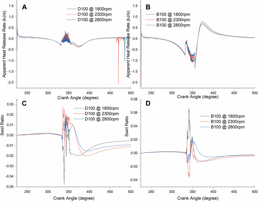
In this direct injection system, the aerodynamics flow nature is promoted by the helical nature of the inlet manifolds and the shape of the valve seat as the external swirl generator and the piston bowl shape as the internal swirl generator. Since strong air motion is desirable irrespective of the injection rate, engine speed variation became a determinant in this simulation. The swirl rapid fluctuation flow period is observed to be so significant during the compression stroke between injection and combustion periods, as shown in Figures 5C, D. The prediction in Figure 5C reveals the buttressing effect of D100 higher in-cylinder pressure, irrespective of the engine speed than B100. Keeping a threshold swirl factor of 0.07, D100 at 2,300 rpm achieved the highest peak swirl ratio of 0.0272 at 336.15 CA, persisting around that value than the engine speeds of 1,800 and 2,800 rpm, which promoted a longer mixing period. B100 at 1,800 rpm achieved the highest peak swirl ratio of 0.0668 at 341.3 CA closer to a threshold of 0.07, followed by the performance of 2,800 rpm, as shown in Figure 5D. It can also be observed that 2,300 rpm yielded the least swirl performance, which may affect the mixing length. The notable decrease, similar to that observed by Atgur et al. (2022), observed in both blend swirl ratios is due to the piston movement from the BTDC.
3.1.2 Air–fuel mix effect
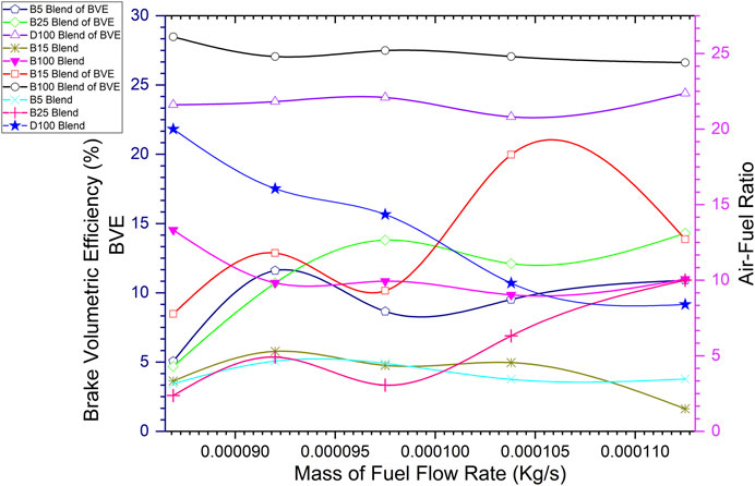
The equivalent ratio is ratio of the mass flow rate of air to fuel. The mixture grade is determined by the air–fuel ratio. The CI engine has a grade band of 18–70 (Pulkrabek, 1999); a lower value than this range indicates a very rich mixture, while a value above this range indicates a very lean mixture. However, good combustion could exist around the very rich mixture zone, according to Taylor, (1985a), as shown in Figure 6.
This experiment presents that the air–fuel ratio of all blends reads below 18 even at an increasing flow rate. Increasing the mass fuel flow rate decreases the air–fuel ratio, irrespective of the blends. An implication of this highly rich mixture combustion is that it may result in a decreased in-cylinder combustion pressure and wall temperature and, consequently, increase the ignition delay if the engine depends so much on a high chamber temperature for an ignition. On the other hand, the reduction in the air–fuel ratio reduces the percentage exergy loss during combustion (Van Basshuysen and Schäfer, 2004).
3.1.3 ICE numerical effluence velocity impact of blends
Here, effluence was better studied numerically under the interactive impact of the in-cylinder injection rate, swirl, tumble, squish, and piston motion. As the engine speed increases, the fuel mass injection rate from the single-point nozzle will increase, thus causing turbulence. The piston harmonic motion on the mixture also increases the turbulence result of the above interactions. In Figure 7, the maximum mass fraction of percentage O2 consumption decreases as speed increases for D100 and B100, upholding the decrease response in the air–fuel ratio to the fuel flow rate. However, the higher consumption rate of B100 in (b), which negates the experimented expectation of Figure 6, resulted from the O2 content in B100, whereas D100 has a void.
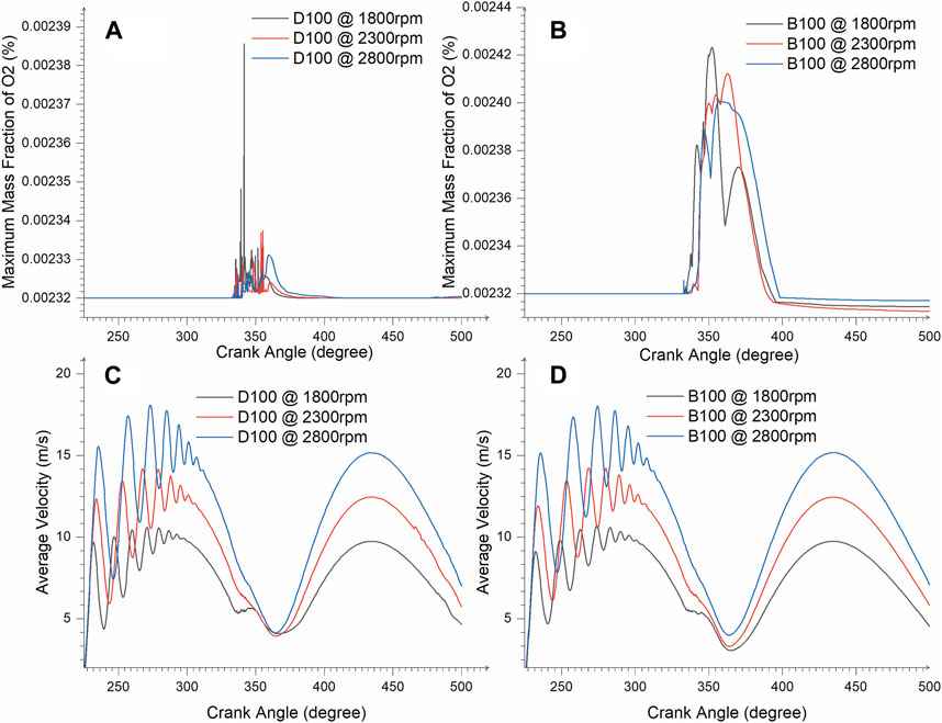
Figure 7. In-cylinder effluence flow plots and oxygen consumption at combustion for both blends at varied speeds.
Instantaneous average velocity during compression and expansion strokes is shown in Figures 7C, D. The engine speed positively increased the effluence flow. The injection flow is significant at a speed of 1,800 rpm and negligible at 2,800 rpm due to the increase in turbulence for D100 and B100. The turbulence is significantly rapid between 225° CA and 290° CA as the piston moves from the BDC to TDC. This rapid flow increases with increase in the engine speed, especially around the wall, as presented in the contours. Immediately after the compression stroke, the minimum effluence existed for both blends at all varied speed. The least is 3.05414 m/s at 365° CA, and the highest is 3.99833 m/s at 364° CA for B100 of 1,800 and 2,800 rpm, respectively, while the least is 3.93886 m/s at 365° CA and the highest is 4.14176 m/s at 364.75° CA for B100 at 2,300 and 2,800 rpm, respectively. The contours shown in Figure 8 provides clearer visualization. Piston upward motion from the BTDC creates higher turbulence at the wall from the tumble and squish of fluid in (a) and (k). During the injection period, the swirl produced from the nozzle through the piston surface is higher. The interaction of fuel density, viscosity, and surface tension plays out here. At 2,300 and 2,800 rpm, B100 creates higher mixing characteristics due to its higher fuel physical properties. This proper mixing, together with higher cetane number and lower heating value (LHV) of B100, promoted a longer combustion period than D100, as shown in Figure 4. During combustion, the effluence severity appears to be greater for both fuels, massive on the wall and piston surface. Immediately after the compression stroke at 369° CA, B100 seemed to possess higher turbulence, which could have stemmed from prolonged combustion.

Figure 8. Velocity contour depicting in-cylinder effluence. Injection period: (B,E,H,L,O,R). During combustion period: (C,F,I,M,P,S). After compression stroke: (D,G,J,N,Q,T). (A–T) are comparison of B100 and D100 blends at specific CA and speeds respectively).
3.2 Blends effect on fuel consumption
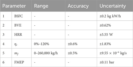
Increasing the load or torque on the engine causes a higher fuel mass flow rate. Applying the fuel flow rate to the BSFC relationship on the blending effect, as shown in Figure 9, presents that the blending increase in pure biodiesel causes a reduction effect on fuel consumption as the fuel flow rate increases. B5 relatively made the highest consumption rate. Ambarita (2018) obtained a similar trend with this study. BSFC is a derived parameter like others in Table 4. Hence, their range and accuracy were not specified on the instrument. All uncertainties were within their 95% level of acceptance. This indicates that errors were quite small for each parameter and even the overall system.
3.3 Engine performance expectation
3.3.1 Mixture efficiency: BVE
It is expected that the BVE positively responds to the increasing air mass flow rate and inversely to engine speed. This provides a brief idea of the engine breathing capacity in the combustion process. Figure 6 shows blend mixing performance on the fuel flow rate relation from the experiment. The BVE of blends increases as the flow rate increases, where B5 yielded the lowest response even at 0.0001125 kg/s, thus yielding 10.9% efficiency. Relatively, the highest performing blend is B100 with 24.8% efficiency, followed by D100 with 22.7% efficiency, specifically at 0.0001038 kg/s.
3.3.2 Combustion efficiency outcome
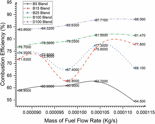
On a holistic performance, all fuel blends were well-burned. The engine is well capable of combusting at a higher fuel flow rate as the burning efficiency increases. The combustion trend is in coherence with the BVE of fuel mixtures, projecting combustion efficiencies to respond positively to the increasing blending proportion of biodiesel, as shown in Figure 10. The increasing trend of blend efficiency is similar to that studied by Li et al. (2022). The least burned fuel blend was B5 with 54.5%, while B100 had 81.47%, and D100 had 88.06% at 0.0001125 kg/s or 75% loading capacity.
3.3.3 Engine heat liberation rate outcome
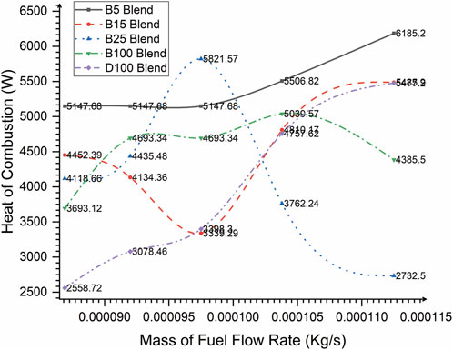
Figures 5A, B show the engine modeling of the HRR for D100 and B100 respectively. It was a zero-heat loss-based assumption; hence, it is called the apparent HRR. Heat transfer from the mixture to the chamber was indicated by the negative decrease from zero. Rapid combustion was predicted to start at 335° CA for both blends, irrespective of the engine speed to approximately 380° CA for D100 and 430° CA for B100. The HRR was predicted to occur in two phases. The first phase was at the spontaneous ignition period, as shown in Figure 4. The second phase was characterized with a significant swirl-amplified ripple occurring at the heart of the combustion period. The highest peak of the HRR D100 was predicted as 0.36892 kJ/s at 342.1° CA, 0.26226 kJ/s at 342.3° CA, and 0.2261 kJ/s at 343.05° CA for 1,800 rpm, 2,300 rpm, and 2,800 rpm, respectively. These peaks occurred at about the ignition period, and the profile of D100 is an inverse of that of B100 at all speeds. This explains the lower activation energy requirement of B100; hence, the higher compression temperature and pressure of D100 yielded a rapid ignition rate, as obtained by Atgur et al. (2022). However, B100 achieved the highest peaks of the HRR with 0.78063 kJ/s at 373.25° CA, 0.69362 kJ/s at 373° CA, and 0.6811 kJ/s at 373° CA prior to combustion decay for a speed of 1,800 rpm, 2,300 rpm, and 2,800 rpm, respectively. This HRR profile may have also been influenced by the piston bowl-shaped design, as obtained by Deresso et al. (2022). The influence of the engine speed on the HRR in D100 states and an increase in speed provided an increase in heat release, whereas B100 obtained an opposite effect. From experimental validation, the fuel flow rate and heating value are directly proportional to the heat of combustion, as shown in Figure 11. Heat liberated from B100 is higher than that in D100; however, a steady increase was observed with D100 as against B100 with respect to the flow rate pointing to the aforementioned speed effect. The blend with the best yield was B5 as it yields the highest heat liberation under an increasing fuel flow rate, as specified on the profile.
3.3.4 Fuel blends and engine losses
During the compression of a mixture, the piston loses some useful energy in overcoming friction. As shown in Figure 12, D100 lost useful pressure force of 3 bar to in-cylinder friction, while B100 and B5 lost 3.136 bar and 3.135 bar, respectively, at constant speed. This suggests that diesel possesses a more lubricating effect and would offer a better exergy advantage than B5 and B100 blends.
4 Conclusion
This study successfully presented a numerical and experimentally validated behavior of the fuel blend flow rate on the ICE, showcasing specific observations on combustion. In other words, the fuel mass flow rate generated by an injector and piston motion significantly affected the engine combustion strength.
➢ Fuel–air mixing quality impacts the ICE combustion performance indexing. Fuel consumption reduces when the biodiesel blending ratio and mass flow rate increase.
➢ Engine breathing efficiency increases at a higher fuel mass flow rate, causing a high burning efficiency of blends. This is the engine stability response to the loading effect.
➢ Engine combustion efficiency could be effectively determined via flue gas up to an 88% accuracy level as the fuel mass flow rate increases.
➢ An ignition delay period of 3° CA CFD prediction will be common to diesel and biodiesel, irrespective of the speed effect; however, biodiesel will have a longer combustion duration.
➢ The fuel mass flow rate increase increases the heat of fuel combustion experimentally. The engine speed effect on the heat liberation rate causes a contrary behavior on biodiesel and diesel fuels when compared numerically.
➢ Lastly, D100 offers lower frictional loss than B100 and B5 in an engine. By the FMEP approach, D100 projects better lubricating and exergy advantages.
Data availability statement
The original contributions presented in the study are included in the article/Supplementary Material; further inquiries can be directed to the corresponding author.
Author contributions
EO: funding acquisition, investigation, and writing–original draft. AA: supervision and writing–review and editing.
Funding
The author(s) declare that financial support was received for the research, authorship, and/or publication of this article. This research was self-funded.
Acknowledgments
The authors thank the staff and management of the Mechanical Engineering Department, University of Benin, for granting access to their laboratory and equipment.
Conflict of interest
The authors declare that the research was conducted in the absence of any commercial or financial relationships that could be construed as a potential conflict of interest.
Publisher’s note
All claims expressed in this article are solely those of the authors and do not necessarily represent those of their affiliated organizations, or those of the publisher, the editors, and the reviewers. Any product that may be evaluated in this article, or claim that may be made by its manufacturer, is not guaranteed or endorsed by the publisher.
References
Abdullah, N. R., Zaharin, M. S. M., Mamat, A. M. I., Nawi, M. R. M., and Sharudin, H. (2015). Effects of ethanol blends on gasoline engine performance and exhaust emissions. J. Teknol. 76. doi:10.11113/jt.v76.5920
Akar, M. A. (2016). Performance and emission characteristics of compression ignition engine operating with false flax biodiesel and butanol blends. Adv. Mech. Eng. 2, 168781401663267–7. doi:10.1177/1687814016632677
Al-Hasan, M. I., and Al-Momany, M. (2008). The effect of iso-butanol-diesel blends on engine performance. Transport 23, 306–310. doi:10.3846/1648-4142.2008.23.306-310
Ambarita, H. (2018). Effect of engine load and biogas flow rate to the performance of a compression ignition engine run in dual-fuel (dieselbiogas) mode. IOP Conf. Ser. Mater. Sci. Eng. 309, 012006. doi:10.1088/1757-899X/309/1/012006
Atelge, M. R., Arslan, E., Krisa, D., Al-Samaraae, R. R., Abut, S., Ünalan, S., et al. (2022). Comparative investigation of multi-walled carbon nanotube modifed diesel fuel and biogas in dual fuel mode on combustion, performance, and emission characteristics. Fuel 313, 1–15. doi:10.1016/j.fuel.2021.123008
Atgur, V., Manavendra, G., Pandurangarao Desai, G., and Nageswara Rao, B. (2022). “CFD combustion simulations and experiments on the blended biodiesel two-phase engine flows,” in Computational fluid dynamics [working title] (IntechOpen). doi:10.5772/intechopen.102088
Caligiuri, C., Bietresato, M., and Renzi, M. (2019). The effect of using diesel-biodiesel-bioethanol blends on the fuel feed pump of a small-scale internal combustion engine. Energy Procedia 158, 953–958. doi:10.1016/j.egypro.2019.01.235
Chen, Z., Zuo, W., Zhou, K., Li, Q., Huang, Y., and E, J. (2023). Multi-objective optimization of proton exchange membrane fuel cells by RSM and NSGA-II. Energy Convers. Manag. 277, 116691. doi:10.1016/j.enconman.2023.116691
Daud, S., Hamidi, M. A., and Mamat, R. (2022). A review of fuel additives’ effects and predictions on internal combustion engine performance and emissions. AIMSE 10, 1–22. doi:10.3934/energy.2022001
Deng, B., Li, Q., Chen, Y., Li, M., Liu, A., Ran, J., et al. (2018). The effect of air/fuel ratio on the CO and NOx emissions for a twinspark motorcycle gasoline engine under wide range of operating conditions. Energy 169, 1202–1213. doi:10.1016/j.energy.2018.12.113
Deresso, H., Nallamothu, R. B., Ancha, V. R., and Yoseph, B. (2022). Numerical study of different shape design of piston bowl for diesel engine combustion in a light duty single-cylinder engine. Heliyon 8, e09602–e09610. doi:10.1016/j.heliyon.2022.e09602
Dubov, G., Bogomolov, A., Azikhanov, S., Strelnikov, P., and Nokhrin, S. (2021). Temperature parameters in the combustion chambers of CUMMINS KTA-50 engines operating on various fuels under different fuel consumption rates. E3S Web Conf. 315, 03011. doi:10.1051/e3sconf/202131503011
Estrada, L., Moreno, E., Gonzalez-Quiroga, A., Bula, A., and Duarte-Forero, J. (2022). Experimental assessment of performance and emissions for hydrogen-diesel dual fuel operation in a low displacement compression ignition engine. Heliyon 8, 092855–e9311. doi:10.1016/j.heliyon.2022.e09285
Feng, R., Chen, K., Sun, Z., Hu, X., Li, G., Wang, S., et al. (2022). A comparative study on the energy flow of a hybrid heavy truck between AMT and MT shift mode under local driving test cycle. Energy Convers. Manag. 256, 115359–115416. doi:10.1016/j.enconman.2022.115359
Feng, R., Li, G., Sun, Z., Hu, X., Deng, B., and Fu, J. (2023). Potential of emission reduction of a turbo-charged non-road diesel engine without aftertreatment under multiple operating scenarios. Energy 263, 125832–125915. doi:10.1016/j.energy.2022.125832
Feroskhan, M., Ismail, S., Kumar, A., Kumar, V., and Aftab, S. K. (2017). Investigation of the effects of biogas flow rate and cerium oxide addition on the performance of a dual fuel CI engine. Biofuels 8, 197–205. doi:10.1080/17597269.2016.1215072
Gnanamoorthi, V., and Vimalananth, V. T. (2020). Effect of hydrogen fuel at higher flow rate under dual fuel mode in CRDI diesel engine. Int. J. Hydrogen Energy 45, 16874–16889. doi:10.1016/j.ijhydene.2020.04.145
Holman, J. P. (2012). Experimental methods for engineers. 8th ed. Boston: McGraw-Hill/Connect Learn Succeed.
Jamrozik, A., Tutak, W., and Grab-Rogaliński, K. (2022). Effects of propanol on the performance and emissions of a dual-fuel industrial diesel engine. Appl. Sci. 12, 5674. doi:10.3390/app12115674
Karami, R., Rasul, M. G., Khan, M. M. K., and Anwar, M. (2019). Performance analysis of direct injection diesel engine fueled with diesel-tomato seed oil biodiesel blending by ANOVA and ANN. Energies 12, 4421. doi:10.3390/en12234421
Knauder, C., Allmaier, H., Sander, D. E., and Sams, T. (2019). Investigations of the friction losses of different engine concepts. Part 1: a combined approach for applying subassembly-resolved friction loss analysis on a modern passenger-car diesel engine. Lubricants 7, 39. doi:10.3390/lubricants7050039
Küçükosman, R., Yontar, A. A., and Ocakoglu, K. (2022). Nanoparticle additive fuels: atomization, combustion and fuel characteristics. J. Anal. Appl. Pyrolysis 165, 105575. doi:10.1016/j.jaap.2022.105575
Kumar, P., and Rehman, A. (2014). Performance and emission characteristics of dual injection in compression ignition (CI) engine. Int. J. Automob. Eng. Res. Dev. 4, 15–28.
Li, Z., Wang, Z., Mo, H., and Wu, H. (2022). Effect of the air flow on the combustion process and preheating effect of the intake manifold burner. Energies 15, 3260. doi:10.3390/en15093260
Liu, H., Wang, Z., Wang, J., He, X., Zheng, Y., Tang, Q., et al. (2015a). Performance, combustion and emission characteristics of a diesel engine fueled with polyoxymethylene dimethyl ethers (PODE3-4)/diesel blends. Energy 88, 793–800. doi:10.1016/j.energy.2015.05.088
Liu, J., Yao, A., and Yao, C. (2015b). Effects of diesel injection pressure on the performance and emissions of a HD common-rail diesel engine fueled with diesel/methanol dual fuel. Fuel 140, 192–200. doi:10.1016/j.fuel.2014.09.109
Mahla, S. K., Das, L. M., and Gupta, N. (2017). Effects of CNG flow rate on combustion, performance and emissions characteristics of biodiesel fuelled diesel engine. Int. J. ChemTech Res. 10, 228–240.
Mao, G., Shi, K., Zhang, C., Chen, S., and Wang, P. (2020). Experimental research on effects of biodiesel fuel combustion flame temperature on NOX formation based on endoscope high-speed photography. J. Energy Insti. 93, 1399–1410. doi:10.1016/j.joei.2020.01.002
Mauro, S., Şener, R., Gül, M. Z., Lanzafame, R., Messina, M., and Brusca, S. (2018). Internal combustion engine heat release calculation using single-zone and CFD 3D numerical models. Int. J. Energy Environ. Eng. 9, 215–226. doi:10.1007/s40095-018-0265-9
Mgbemene, C. A., Kalu-Uka, A. C., Odukwe, A. O., Kalu-Uka, G. M., Ezema, I. C., and Ogbuka, C. U. (2019). Analysis of an automatic control system for the blending of petrol with corrosion inhibitor in cranked. Direct continuous electronic fuel injection (DC-EFI) automobile engines. Int. J. Eng. Res. 6 doi:10.17577/IJERTV8IS060338
Mishra, P. C. (2013). Modeling for friction of four stroke four cylinder in-line petrol engine. Tribol. Ind. 35, 237–245.
Mohammed, M. K., Balla, H. H., Al-Dulaimi, Z. M. H., Kareem, Z. S., and Al-Zuhairy, M. S. (2021). Effect of ethanol-gasoline blends on SI engine performance and emissions. Case Stud. Therm. Eng. 25, 100891. doi:10.1016/j.csite.2021.100891
Onojowho, E. E., Obayopo, S. O., and Asere, A. A. (2019). “Optimization of biodiesel production from Khaya senegalensis oil using heterogeneous catalyst,” in Diversification of developing economies: imperatives for sustainable environment and technological innovations (Ile-Ife: African Centre of Excellence, Obafemi Awolowo University, Ile-Ife.: OAU Printing Press), 388. Available at: www.oautekconf.org.
Onukwuli, O. D., Esonye, C., and Ofoefule, A. U. (2021). Combustion exhaust release impact, diesel engine performance, and optimization studies of green diesel-petrodiesel blend in a high compression ratio direct-injection compression-ignition engine. Adv. Mech. Eng. 13, 168781402110187. doi:10.1177/16878140211018778
Orihuela, M. P., Haralampous, O., Chacartegui, R., Torres García, M., and Martínez-Fernández, J. (2019). Numerical simulation of a wall-flow particulate filter made of biomorphic silicon carbide able to fit different fuel/biofuel inputs. Processes 7, 945. doi:10.3390/pr7120945
Park, H., Shim, E., Lee, J., Oh, S., Kim, C., Lee, Y., et al. (2022). Large–squish piston geometry and early pilot injection for high efficiency and low methane emission in natural gas–diesel dual fuel engine at high–load operations. Fuel 308, 122015. doi:10.1016/j.fuel.2021.122015
Parthasarathy, M., Ramkumar, S., and Isaac Joshua Ramesh Lalvani, J. (2019). Influence of various flow rates of CNG in CI engine with blend of tamanu methyl ether and ethanol. Int. J. Veh. Struct. Syst. 11. doi:10.4273/ijvss.11.2.06
Perumal Venkatesan, E., Balasubramanian, D., Samuel, O. D., Kaisan, M. U., and Murugesan, P. (2021). “Effect of hybrid nanoparticle on DI diesel engine performance, combustion, and emission studies,” in Novel internal combustion engine technologies for performance improvement and emission reduction energy, environment, and sustainability. Editors A. P. Singh, and A. K. Agarwal (Singapore: Springer Singapore), 235–263. doi:10.1007/978-981-16-1582-5_10
Pham, Q., Park, S., Agarwal, A. K., and Park, S. (2022). Review of dual-fuel combustion in the compression-ignition engine: spray, combustion, and emission. Energy 250, 123778. doi:10.1016/j.energy.2022.123778
Potdukhe, S. P., and Deshmukh, M. M. (2015). Modeling and energy analysis of a diesel and biodiesel fuelled engine. Int. J. Sci. Res. 4, 89–93.
Prasad, K. S., and Saravanan, R. (2021). Study of impact of CNG flow rate and speed on the performance and emission characteristics of DTSI engine using petrol-ethanol fuel blend. J. Mech. Eng. Res. Dev. 44, 01–09.
Pulkrabek, W. W. (1999). Engineering fundamentals of the internal combustion engine. First edition. Upper Saddle River, New Jersey 07458: Prentice Hall.
Rai, A., Kumar, D., Sonawane, U., and Agarwal, A. K. (2021). “Dimethyl ether spray characteristics for compression ignition engines,” in Novel internal combustion engine technologies for performance improvement and emission reduction energy, environment, and sustainability. Editors A. P. Singh, and A. K. Agarwal (Singapore: Springer Singapore), 79–103. doi:10.1007/978-981-16-1582-5_4
Said, Z., Le, D. T. N., Sharma, P., Dang, V. H., Le, H. S., Nguyen, D. T., et al. (2022). Optimization of combustion, performance, and emission characteristics of a dual-fuel diesel engine powered with microalgae-based biodiesel/diesel blends and oxyhydrogen. Fuel 326, 124987. doi:10.1016/j.fuel.2022.124987
Schmidt, D. P., Nouar, I., Senecal, P. K., Rutland, C. J., Martin, J. K., and Reitz, R. D. (1999). Pressure-swirl atomization in the near field. Warrendale, Pa, USA: SAE.
Shaafi, T., and Velraj, R. (2015). Influence of alumina nanoparticles, ethanol and isopropanol blend as additive with diesel-soybean biodiesel blend fuel: combustion, engine performance and emissions. Renew. Energy 80, 655–663. doi:10.1016/j.renene.2015.02.042
Shahabuddin, M., Liaquat, A. M., Masjuki, H. H., Kalam, M. A., and Mofijur, M. (2013). Ignition delay, combustion and emission characteristics of diesel engine fueled with biodiesel. Renew. Sustain. Energy Rev. 21, 623–632. doi:10.1016/j.rser.2013.01.019
Stępień, Z., Pielecha, I., Szwajca, F., and Cieślik, W. (2022). Effects of ethanol admixtures with gasoline on fuel atomization characteristics using high-pressure injectors. Energies 15, 2926. doi:10.3390/en15082926
Sun, D., Cai, W., Li, C., and Lu, J. (2021). Experimental study on atomization characteristics of high-energy-density fuels using a fuel slinger. Energy 234, 121222. doi:10.1016/j.energy.2021.121222
Taylor, C. F. (1985a). The internal-combustion engine in theory and practice. Volume 11: combustion, fuels, materials, design. 2nd ed. Cambridge, Mass: M.I.T. Press. rev.
Taylor, C. F. (1985b). The internal-combustion engine in theory and practice. Volume I: thermodynamics, fluid flow, performance. 2nd ed. Cambridge, Mass: M.I.T. Press. rev.
Ude, C. N., Onukwuli, O. D., Nwobi –Okoye, C., Anisiji, O. E., Atuanya, C. U., and Menkiti, M. C. (2020). Performance evaluation of cottonseed oil methyl esters produced using CaO and prediction with an artificial neural network. Biofuels 11, 77–84. doi:10.1080/17597269.2017.1345355
Van Basshuysen, R.,, and Schäfer, F. (2004). Internal combustion engine handbook: basics, components, systems, and perspectives (Warrendale, Pa: SAE International).
Weber, C. (1931). Zum Zerfall eines Flüssigkeitsstrahles. ZAMM 11, 136–154. doi:10.1002/zamm.19310110207
Wysocki, O., Kropiwnicki, J., Zajdziński, T., and Czyżewicz, J. (2018). Experimental determination of general characteristic of internal combustion engine using mobile test bench connected via Power Take-Off unit. IOP Conf. Ser. Mater. Sci. Eng. 421, 042087. doi:10.1088/1757-899X/421/4/042087
Yamin, J. A., and Hdaib, I. I. (2022). Analysis of internal combustion engine performance using design of experiment. Teh. Vjesn. 29. doi:10.17559/TV-20210312194600
Zardoya, A. R., Lucena, I. L., Bengoetxea, I. O., and Orosa, J. A. (2022). Research on an internal combustion engine with an injected pre-chamber to operate with low methane number fuels for future gas flaring reduction. Energy 253, 124096. doi:10.1016/j.energy.2022.124096
Zuo, W., Chen, Z., E, J., Li, Q., Zhang, G., and Huang, Y. (2023a). Effects of structure parameters of tube outlet on the performance of a hydrogen-fueled micro planar combustor for thermophotovoltaic applications. Energy 266, 126434. doi:10.1016/j.energy.2022.126434
Zuo, W., Li, D., E, J., Xia, Y., Li, Q., Quan, Y., et al. (2023b). Parametric study of cavity on the performance of a hydrogen-fueled micro planar combustor for thermophotovoltaic applications. Energy 263, 126028. doi:10.1016/j.energy.2022.126028
Zuo, W., Wang, Z., E, J., Li, Q., Cheng, Q., Wu, Y., et al. (2023c). Numerical investigations on the performance of a hydrogen-fueled micro planar combustor with tube outlet for thermophotovoltaic applications. Energy 263, 125957. doi:10.1016/j.energy.2022.125957
Zuo, W., Zhang, Y., E, J., Li, J., Li, Q., and Zhang, G. (2022). Performance comparison between single S-channel and double S-channel cold plate for thermal management of a prismatic LiFePO4 battery. Renew. Energy 192, 46–57. doi:10.1016/j.renene.2022.04.116
Nomenclature
Keywords: fuel flow rate, piston frictional losses, engine heat liberation rate, combustion efficiency, internal combustion engine numerical effluence
Citation: Onojowho EE and Asere AA (2024) Effects of the fuel blend flow rate on engine combustion performance. Front. Energy Res. 12:1335507. doi: 10.3389/fenrg.2024.1335507
Received: 09 November 2023; Accepted: 02 April 2024;
Published: 30 May 2024.
Edited by:
Bengi Şanlı, Mersin University, TürkiyeReviewed by:
Gökhan Tüccar, Adana Science and Technology University, TürkiyeWei Zuo, Wuhan University of Science and Technology, China
Rajiv Kumar, Birla Institute of Technology, India
Copyright © 2024 Onojowho and Asere. This is an open-access article distributed under the terms of the Creative Commons Attribution License (CC BY). The use, distribution or reproduction in other forums is permitted, provided the original author(s) and the copyright owner(s) are credited and that the original publication in this journal is cited, in accordance with accepted academic practice. No use, distribution or reproduction is permitted which does not comply with these terms.
*Correspondence: E. E. Onojowho, ZWZlLmVsaWphaEBnbWFpbC5jb20=
‡ORCID: E. E. Onojowho, orcid.org/0000-0002-3253-7940
†Present addresses: E. E. Onojowho, Department of Mechanical Engineering, University of Nigeria, Nsukka, Nigeria
A. A. Asere, Department of Automobile Engineering, Elizade University Ilara-Mokin, Nsukka, Ilara-Mokin
 E. E. Onojowho
 A. A. Asere†