 Shouguo Yang1,2
 Ning Xu
 Xiaofei Zhang
- 1College of Safety Science and Engineering, Xi’an University of Science and Technology, Xi’an, China
- 2State Key Laboratory of Gas Disaster Detecting, Preventing and Emergency Controlling, Chongqing, China
- 3Shaanxi Yanchang Petroleum Yulin Kekegai Coal Industry Co Ltd., Yulin, China
The determination of the ‘three zones’ range within the overlying strata in goaf of paramount importance for effective gas extraction in the goaf and the prevention and control of gas levels exceeding limits in both the working face and the upper corner. Due to the influence of their dip angles, the existing formula used to calculate the breaking boundary angle of the overlying strata in the goaf of horizontal coal seams is no longer suitable for steep coal seams. In response to this issue, the movement law of the overlying strata during the mining of steep coal seams was analyzed and a formula for calculating the breaking boundary angle of the overlying strata in the goaf of steep coal seams was derived. The theoretical calculation formula was applied to the 3,103 fully mechanized mining face of a certain mine in southwest China, and compared and analyzed the results with numerical simulation and on-site measurement using microseismic monitoring technology. The research findings demonstrate that the formula effectively quantifies the ‘three zones’ range within the overlying strata in the goaf of steep coal seams. The ‘three zones’ range in steep coal seams is primarily influenced by factors such as the length of the filling area in the lower part of the goaf, changes in roof lithology, coal seam dip angle, length of the working face, and overburden load. The longer the length of the filling area, the larger the upper breaking boundary angle and the smaller the lower breaking boundary angle of the fracture zone. Based on the research results of three methods, the height of the caving zone in the 3,103 fully mechanized mining face is from 6.93 m to 7.7 m, the height of the fracture zone is from 28.91 m to 34.2 m, the lower breaking boundary angle of the fracture zone is from 40° to 44.5°, and the upper breaking boundary angle of the fracture zone is from 57.7° to 62°. The research results offer robust technical support and theoretical guidance for the determination of the ‘three zones’ range within the overlying strata during the future mining of steep coal seams.
1 Introduction
The mining of coal seams is accompanied by the movement and deformation of surrounding rock formations and surface areas, which results in the formation of caving, fracture, and curved subsidence zones within the overlying strata. In the fracture zone, where fractures are well-developed and facilitate gas circulation (Ma et al., 2013; Wang et al., 2015; Huang et al., 2018). The gas extraction boreholes in goaf are typically positioned at this location (Ye et al., 2017; Zhang Q. M. et al., 2022; Zhao et al., 2023). Therefore, it holds paramount significance to investigate the extent of the overlying strata’s caving zone, fracture zone, and curved subsidence zone (collectively referred to as the ‘three zones’), for efficient gas extraction in goaf areas, as well as for gas limit control in mining faces and upper corners. This research is instrumental in ensuring the safety of underground personnel and property.
Numerous scholars have conducted extensive and rich research on this issue. Wang et al. (Wang et al., 2022) established a prediction model for the height of horizontal coal seam fracture zone based on the quantitative relationship between the mining thickness of coal seams, the deformation amount of rock layers of caving zone and fracture zone, and the surface subsidence value. Xu et al. (Xu et al., 2023) established a relationship between the bearing strength of masonry beams and the height of the caving zone using methods such as UDEC numerical simulation and on-site 3D borehole television imaging, combined with the “S-R″ stability theory. Zhou et al. (Zhou and Yu, 2022) studied the height of the ‘three zones’ of overlying strata in the goaf of gently inclined and extremely thick coal seams through similar simulation experiments, numerical simulations, and on-site measurements. Liu et al. (Liu et al., 2019) proposed a method for predicting the height of the fracture zone based on multiple regression analysis and geographic information systems. Cheng et al. (Cheng et al., 2017) used microseismic monitoring technology to study the distribution patterns of microseismic events released from coal mine roof rock masses in both vertical and horizontal directions. Chen et al. (Chen et al., 2022) systematically studied the movement law and mining pressure of overlying strata on large-angle fully mechanized mining faces through theoretical analysis, similar material simulation, numerical calculation, and on-site monitoring methods. Lai et al. (Lai et al., 2021) used a research method that combines similarity simulation experiments, numerical simulations, and on-site monitoring to analyze the migration law of overlying strata and the distribution characteristics of fracture zone in coal seam mining under thick and loose layers. Yang et al. (Yang et al., 2021) derived a formula based on the thin plate theory for calculating the basic roof stress distribution in highly inclined coal seams. Xu et al. (Xu et al., 2018) derived a formula for calculating the fracture angle of the overlying strata in a horizontal coal seam goaf based on the theory of key layers, and verified the rationality and reliability of the formula through physical simulation experiments.
The research findings mentioned above have significantly advanced the study of the ‘three zones’ within the overlying strata in goaf, playing a pivotal role in both theoretical research and practical engineering applications. However, much of the existing research predominantly focuses on analyzing the height of the ‘three zones’, with limited attention directed toward the determination of the breaking boundary angle of the fracture zone. The breaking boundary angle of the fracture zone represents a crucial parameter for accurately defining the ‘three zones’ range within the overlying strata in the goaf and for planning the layout of gas extraction boreholes in the goaf (Cui et al., 2019a; Hu and Cai, 2020; Zhu et al., 2020). In the case of steep coal seams, rock blocks that collapse due to the influence of the coal seam’s dip angle will slide downward along the inclined direction of the working face, filling the lower section of the goaf (Yao et al., 2017; Ye et al., 2018; Liu et al., 2020). Given the stabilizing influence of these rock blocks in the filling area on the roof, the conventional calculation formula for the breaking angle of the overlying strata in goaf based on the horizontal coal seams, is no longer suitable for steep coal seams. Consequently, it is particularly imperative to research the breaking boundary angle of the overlying strata in the goaf of steep coal seams.
Numerous studies have confirmed the effectiveness of numerical simulation methods in studying fracture evolution, such as reference (Huang et al., 2022; Luo et al., 2022; Zheng et al., 2022; Huang et al., 2023). In reference (Yang et al., 2023a), based on microseismic monitoring technology, the author studied the height of the fracture zone in the goaf of steep coal seams and compared with numerical simulation results. The obtained results are consistent, which presents a new technical approach for determining the height of the ‘three zones’ within overlying strata in the goaf of steep coal seams. On this basis, starting from the movement law of the overlying strata during the mining of steep coal seams, this article derives a formula for calculating the breaking boundary angle of the overlying strata in the goaf of steep coal seams. And in theory, the ‘three zones’ range of the overlying strata in the goaf of steep coal seams is quantified. Taking the 3,103 fully mechanized mining face of a certain mine in southwestern China as the background, a combination of theoretical calculation, numerical simulation, and on-site measurement via microseismic monitoring technology was used to study the ‘three zones’ range of overlying strata in the goaf of steep coal seams. The research outcomes supply robust technical support and theoretical guidance for the determination of the ‘three zones’ range within the overlying strata during future mining operations in steep coal seams.
2 Theoretical derivation of the ‘three zones’ range within the overlying strata in the goaf of steep coal seams
2.1 Movement law of overlying strata during mining of steep coal seams
During the mining of steep coal seams, the overlying strata are repeatedly disturbed and cause damage under their gravity load. As the mining face progresses, certain segments of the overlying strata at a particular height undergo collapse (Zhang et al., 2023). Owing to the influence of the seam’s inclination angle, the collapsed rock blocks will slide toward the lower portion of the working face and subsequently fill the goaf. The lower filling area of the goaf plays a certain supporting role in the roof (Lai et al., 2020). After the completion of mining in the steep coal seam working face, it can be categorized into distinct sections, namely, the compacted filling area, the fully filling area, and the partial filling area, in a bottom-to-top arrangement along the direction of the working face inclination, as illustrated in Figure 1.
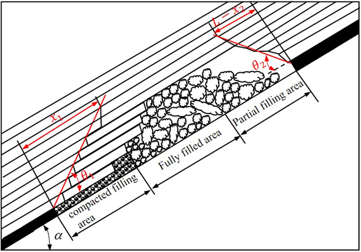
FIGURE 1. Schematic illustration of overlying strata movement during mining of steep coal seams.
In the figure,
Where
2.2 Mechanical derivation of breaking boundary angle for the fracture zone
When analyzing the fracture characteristics of the fracture zone, the overlying strata in the goaf can be simplified as a combination of two rock beams, namely, the caving zone and the fracture zone, as shown in Figure 2.

FIGURE 2. Analysis model for fracture characteristics of fracture zone.
The disintegration of rock layers within the caving zone results in the filling of the goaf. It is important to note that the fully filled area offers less supporting ability to the roof in comparison to the compacted filling area. Consequently, the analysis of rock beams within the fracture zone focuses exclusively on the supporting ability by the compacted filling area for the rock beams. Reference (Wang et al., 2016) provides a calculation formula for the length of the compacted filling area in the goaf, as follows:
Where
When calculating the ultimate span of the caving zone, the rock beam in the caving zone is considered a fixed beam structure. The load exerted by the overlying strata on the rock beam in the caving zone is simplified as a uniformly distributed load, as shown in Figure 3.
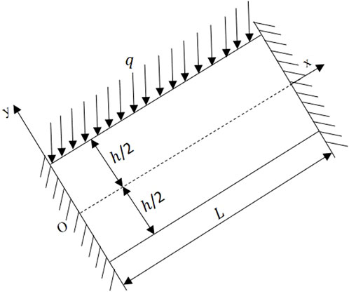
FIGURE 3. Stress analysis of rock beams in the caving zone.
In the figure,
When the maximum tensile stress
Combining formulas (3) and (6), it can be obtained that the length
The mechanical analysis of the rock beam in the fracture zone is carried out using a fixed support beam structure. The load of the overlying strata and the supporting force load of the compacted filling area are simplified as uniformly distributed loads acting on the rock beam in the fracture zone, as shown in Figure 4.
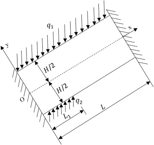
FIGURE 4. Stress analysis of rock beams in fracture zone.
In the figure,
According to the principle of superposition of bending moments, the bending moment
According to formula (10), the tensile stress
Where
Where
When the tensile stress at
3 Numerical simulation of the ‘three zones’ range within overlying strata in the goaf of steep coal seams
3.1 Model establishment and parameter settings
The discrete element method is a commonly used method for studying the ‘three zones’ range of overlying strata in goaf (Qin et al., 2023). 3DEC, as a numerical simulation software that uses the discrete element method to simulate the mechanical properties of discrete media, can effectively simulate the movement and fracture structure of overlying rock layers during coal mining. To verify the reliability of the theoretical formula of the fracture zone range within overlying strata in the goaf of steep coal seam, 3DEC software was used to simulate the fracture characteristics of overlying strata in steep coal seam mining. The geometric parameters and physical parameters of the model were selected from the K1 coal seam of 3,103 fully mechanized mining face in a mine in southwest China. The coal seam has a dip angle of 47° with an average thickness of 2.3 m. The inclined length of the working face is 135 m, the strike length of the working face is 1,190 m, and the buried depth of the coal seam is 550 m. To ensure calculation precision, the model was set to a length of 200 m along the strike direction of the working face and 200 m along the dip direction. Solid coal pillars, measuring 50 m in width, were retained on both sides of the working face’s strike direction. The coal seam was excavated along the strike direction of the working face, covering an excavation length of 100 m. Among them, the X direction is the strike direction of the working face, and the Y direction is the tendency direction of the working face. The total size of the calculated model is: length × width × height is 200 m × 200 m × 270 m. According to the actual geological conditions of the coal seam and rock layer in the 3,103 working face, the model is divided into rock blocks of different thicknesses. At the same time, cut the rock blocks above the coal seam to form joints. After the formation of rock joints, the entire model is meshed using a tetrahedral mesh. The established model consists of 1,364,797 elements, as shown in Figure 5.
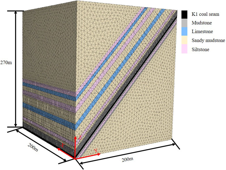
FIGURE 5. Schematic diagram of numerical model.
The overlying and underlying strata of the coal seams primarily consist of sandy mudstone, mudstone, limestone, and siltstone rock materials. In the graphical representation, the yellow area corresponds to sandy mudstone, the purple area to siltstone, the blue area to limestone, the gray area to mudstone, and the black area represents the coal seams. The Mohr-Coulomb model is selected for the constitutive model of the blocks in the numerical model, and the Coulomb slip model is selected for the constitutive model of the joints. Subsequently, the rock mechanics parameters of the unit grids were set. These parameters were determined based on both the actual geological conditions of the coal seam at the site and rock mechanics experiments measurements. The physical and mechanical properties of different coal rocks and joint mechanics properties are shown in Table 1 and Table 2.
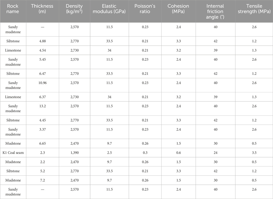
TABLE 1. Physical and mechanical parameters of different coal rocks.
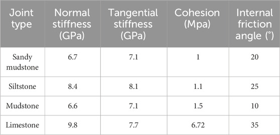
TABLE 2. Mechanical parameters of different coal rock joints.
Due to the height of the model not reaching the surface, the original rock stress load of 6.86 MPa was applied above the model through calculation. According to the lateral pressure coefficient of the coal seam being 1.2, the applied confining pressure was 8.4 MPa. The four sides of the model were fixed, the bottom was fixed, and the top was a free surface. Set the initial velocity of the plane at X = 0 m and X = 200m–0 m/s, the plane displacement at Y = 0 m and Y = 200 m–0m, and the plane displacement at Z = 0m–0 m.
3.2 Analysis of numerical simulation results
After the coal seam is extracted, the overlying strata in goaf are affected by mining damage and stress disturbance of surrounding rocks, forming a certain range of caving zone and fracture zone (Tu et al., 2018; Zhang H. D. et al., 2022). Accurately predicting the range of fracture zone is great significance for the layout of gas extraction boreholes in the goaf. The structural characteristics of the ‘three zones’ of the overlying strata in the goaf, namely, the separation fissure above the fracture zone, are one of the methods for distinguishing the range of fracture zones. Meanwhile, due to the completion of coal seam mining, the overlying strata will exhibit varying degrees of displacement distribution in the vertical direction. By analyzing the range of different displacement zones, the range of the caving zone can be determined. Therefore, by analyzing the vertical displacement distribution of the model after excavation and combining it with the structural characteristics of the ‘three zones’ of the overlying strata, the range of the ‘three zones’ obtained from numerical simulation can be accurately determined. To facilitate the comparison of the ‘three zones’ range of the overlying strata in the goaf, the upper threshold in the displacement cloud map was set to 0m, and the lower threshold was set to 8 m. The parts with displacement exceeding 0 m in the cloud map are all blue, and the parts below 8 m are all red (Yang et al., 2023b). When the working face is excavated for 100m, the displacement cloud map along the inclined direction of the working face is shown in Figure 6.
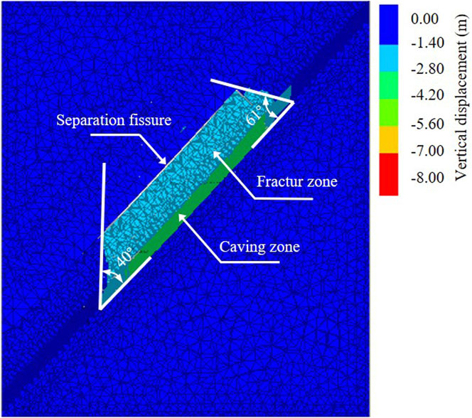
FIGURE 6. Displacement cloud map of the inclined direction during 100 m excavation of the working face.
From Figure 6, it can be seen that the overlying strata exhibit obvious ‘three zones’ structural features, namely, the caving zone, fracture zone, and the appearance of obvious separation fissure above the fracture zone. Based on this, it is determined that the green part in the figure is the caving zone, and the light blue part is the fracture zone. After analysis, the goaf caving zone is located in the mudstone above the K1 coal seam, with a height of 6.93 m. The fracture zone is located in the siltstone and sandy mudstone above the caving zone, with a height of 28.91 m. The lower breaking boundary angle of the fracture zone is 40°, and the upper breaking boundary angle is 61°. From the breaking boundary angle of the fracture zone, it can be seen that the lower breaking boundary angle is significantly smaller than the upper breaking boundary angle. This indicates that due to the influence of the dip angle, the collapsed rock blocks in the caving zone fill the lower area of the goaf. The supporting effect of the filling area causes the overall range of the fracture zone to move upwards, presenting an asymmetric feature. The numerical simulation results conform to the movement law of the overlying strata during the mining of steep coal seams.
4 On-site test of the ‘three zones’ range within overlying strata in goaf of steep coal seam based on microseismic monitoring
4.1 Microseismic monitoring technology for fracture of overlying strata in goaf
Coal rock is a stress medium, under the influence of coal seam mining, generates elastic waves when the overlying strata rupture (Cui et al., 2019b; Hou et al., 2020). These elastic waves propagate within the coal rock mass, constituting microseismic events. Based on microseismic monitoring systems, these elastic waves can be identified, captured, and collected. Processing and analyzing elastic waves can locate the location of microseismic events in three-dimensional space. By using the P-wave (longitudinal wave) localization algorithm, the time, location, energy, and amplitude of microseismic events can be determined. Subsequently, based on the spatial distribution of microseismic events, the distribution status, evolution process, and trend of fractures can be analysed. Then the ‘three zones’ range of overlying strata in the goaf can be determined. The principle of microseismic monitoring is shown in Figure 7.
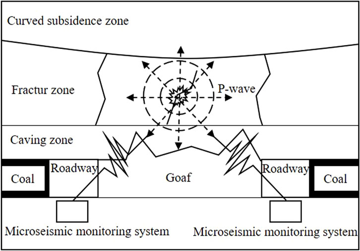
FIGURE 7. Schematic diagram of microseismic monitoring principle.
4.2 Arrangement of microseismic monitoring
The key components of a microseismic monitoring system include sensors, collectors, and hosts. Sensors can identify and capture the elastic waves generated by coal and rock mass fractures. The acquisition instrument can collect and record the captured microseismic signals. The host can view, analyze, and process the collected microseismic signals. To ensure the effectiveness of monitoring, a total of 4 collection instruments and 12 sensors are arranged in combination with the mine tunnel system. Two acquisition devices and six sensors are respectively arranged in the 3,103 haulage roadway and the 3,103 return air roadway, with each acquisition device equipped with three sensors. The position of the first arranged sensor is 50 m ahead of the working face, with a sensor spacing of 50m, as shown in Figure 8.

FIGURE 8. Layout of microseismic monitoring in the working face.
4.3 Analysis of microseismic monitoring results
After the completion of coal seam mining in the working face, microseismic data recorded by the four acquisition instruments is extracted. The specific acquisition instrument used is the YTZ-3 (B) type microseismic monitor. Since each acquisition instrument simultaneously records microseismic signals captured by three sensors, the microseismic signals from the same sensor are considerably dispersed. To facilitate the analysis and processing of microseismic data recorded by each sensor, dedicated YTZ-3 data decoding software is employed to decode this information. Throughout the coal seam mining process, various types of noise will be generated, leading the microseismic monitoring system to collect a considerable amount of invalid data. During practical testing, thousands of event data points were identified in each work shift. To obtain effective data more accurately, manual identification and selection of microseismic data captured by each sensor are carried out. Calculate the position coordinates and energy values of the seismic source using the YTZ-3 system software for manually identified and selected microseismic data. The vertical distance from the seismic source point to the coal seam and the projected coordinate on the inclined section can be calculated from the position coordinates of the seismic source, as shown in Figure 9.
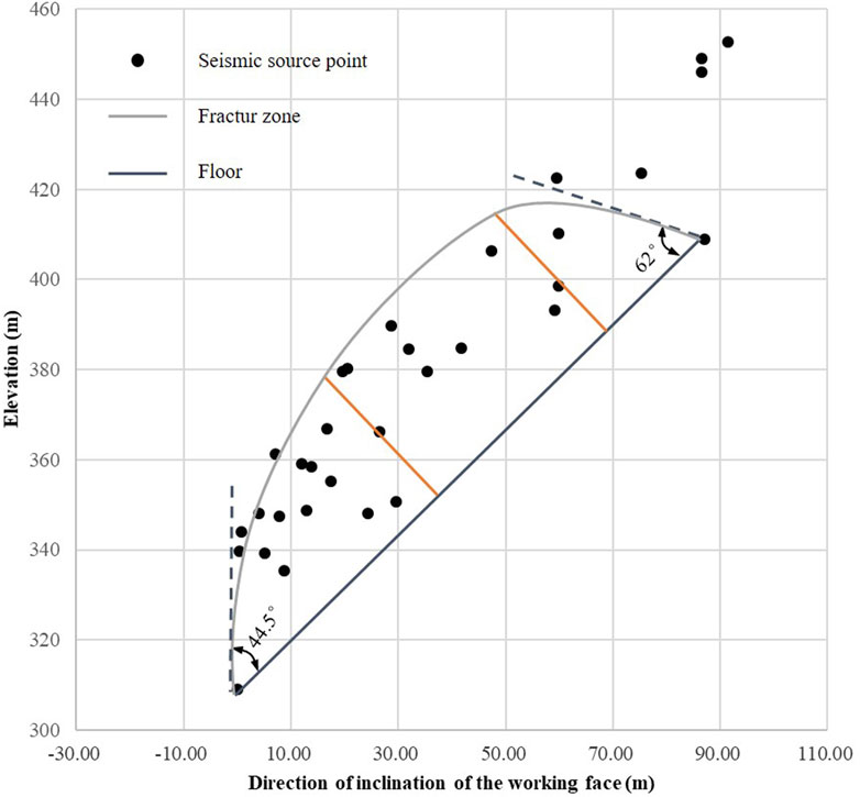
FIGURE 9. Seismic source distribution of microseisms in the inclined direction of coal seams.
From the figure, it can be seen that the maximum height of a typical microseismic event is 34.2m, the minimum height is 6.8m, and the average height is 23.6 m. Therefore, the height of the caving zone is 6.8m, and the height of the fracture zone is 34.2 m. After measurement, the lower breaking boundary angle of the fracture zone is 44.5°, and the upper breaking boundary angle is 62°.
5 Analysis and discussion
According to the coal and rock parameters of the 3,103 fully mechanized mining face, the height of the caving zone is calculated by empirical formula (13) to be 5.5–9.9m, with an average of 7.7 m. Formula (14) calculates that the height of the fracture zone is 26.0–37.2m, with an average of 31.6 m.
Where
From this, the fracture positions
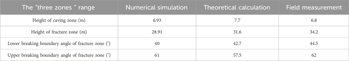
TABLE 3. Calculation results of the ‘three zones’ range of different methods.
From Table 3, it can be seen that the results of the ‘three zones’ range of the overlying strata in the goaf of the steep coal seam calculated by the three methods are in good agreement, and the differences are all within 5. This indicates that the theoretical calculation formula derived in this article can accurately calculate the ‘three zones’ range of the overlying strata in the goaf of steep coal seams. From the research results of the three methods, it can be found that due to the influence of the coal seam dip angle, the lower breaking boundary angle of the fracture zone of the overlying strata in the goaf is smaller than the upper breaking boundary angle. Compared with the ‘three zones’ within overlying strata in the goaf of horizontal coal seams, the overall upward movement of the fracture zone in steep coal seams presents an asymmetric feature. The final determination is that the height of the caving zone in the 3,103 fully mechanized mining face was from 6.93 m to 7.7m, the height of the fracture zone was from 28.91 m to 34.2m, the lower breaking boundary angle of the fracture zone was from 40° to 44.5°, and the upper breaking boundary angle of the fracture zone was from 57.5° to 62°. According to this scope, three strike long boreholes were constructed in the 3,103 working face for gas extraction, as shown in Figure 10.
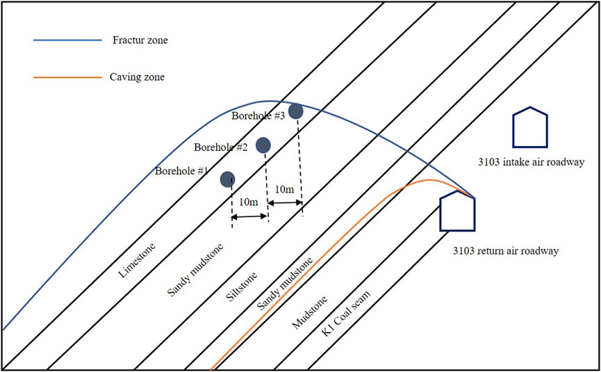
FIGURE 10. Section diagram of inclined direction of boreholes arrangement in the 3,103 working face.
The borehole spacing is 10m, the aperture is 120 mm and they are all located above the 3,103 return air roadway. During the entire extraction process, the average gas extraction concentration was 53.55% and the average gas extraction amount was 5.37 m³/min. After extraction, the gas concentration in the upper corner of the return air roadway was about 0.4%, and the gas concentration in the return air roadway was about 0.3%, which achieves a good gas prevention and control effect. The research methods and results can provide guidance and reference for the prediction of the ‘three zones’ range of overlying strata in goaf of similar coal seams.
On the other hand, the theoretical calculation of the upper breaking boundary angle of the fracture zone on the overlying strata of steep coal seam will be slightly lower than the numerical simulation and on-site measurement values. This is because in the theoretical derivation process, to simplify the calculation formula, only the support of the compacted filling area for the rock beam of the fracture zone was considered. In fact, the fully filled area also has a certain support for the rock beam of the fracture zone. From formula (11), it can be seen that the ‘three zones’ range of steep coal seams is mainly limited by various factors such as the length of the filling area in the lower part of the goaf, changes in roof lithology, coal seam dip angle, coal seam thickness, working face length, overburden load, etc. When all conditions remain unchanged and only increase the value of
6 Conclusion
To study the ‘three zones’ range within overlying strata in the goaf of steep coal seams, a formula for calculating the breaking boundary angle within overlying strata fracture zone in the goaf of steep coal seams was derived based on the movement law of overlying strata during mining. Taking the 3,103 fully mechanized mining face of a certain mine in southwestern China as the background, the ‘three zones’ range within overlying strata in the goaf was studied through three methods: theoretical calculation, numerical simulation, and on-site measurement based on microseismic monitoring technology. Draw the following conclusion:
(1) The derived formula for calculating the breaking boundary angle of the overlying rock strata in the goaf of steep coal seams can effectively quantify the ‘three zones’ range of the overlying rock strata in the goaf of steep coal seams.
(2) From the theoretical formula, it can be seen that the scope of the ‘three zones’ in steep coal seams is mainly limited by various factors such as the length of the filling area in the lower part of the goaf, changes in roof lithology, dip angle of the coal seam, thickness of the coal seam, length of the working face, and overburden load. Among them, the longer the filling area, the larger the upper breaking boundary angle of the fracture zone and the smaller the lower breaking boundary angle.
(3) Based on the research results of three methods, the height of the caving zone in the 3,103 fully mechanized mining face is from 6.93 m to 7.7m, the height of the fracture zone is from 28.91 m to 34.2m, the lower boundary of the fracture zone is from 40° to 44.5°, and the upper boundary of the fracture zone is from 57.7° to 62°. The research methods and results can provide guidance and reference for the prediction of the ‘three zones’ range of overlying strata in goaf of similar coal seams.
Data availability statement
The original contributions presented in the study are included in the article/Supplementary Material, further inquiries can be directed to the corresponding author.
Author contributions
SY: Conceptualization, Formal Analysis, Funding acquisition, Methodology, Project administration, Supervision, Validation, Writing–original draft, Writing–review and editing. NX: Formal Analysis, Investigation, Methodology, Validation, Visualization, Writing–original draft, Writing–review and editing. HL: Investigation, Writing–original draft. XZ: Formal Analysis, Writing–original draft. SM: Formal Analysis, Writing–original draft.
Funding
The author(s) declare financial support was received for the research, authorship, and/or publication of this article. This study was funded by the Open Fund of the State Key Laboratory of Gas Disaster Detecting, Preventing and Emergency Controlling, No. 2022SKLKF05.
Acknowledgments
First of all, we acknowledge the editors and reviewers for their valuable comments; secondly, we are grateful for the help of the fund from the State Key Laboratory of Gas Disaster Detecting, Preventing and Emergency Controlling; finally, we appreciate the authors of all references for their achievements that bring us new ideas.
Conflict of interest
Author HL was employed by Shaanxi Yanchang Petroleum Yulin Kekegai Coal Industry Co Ltd.
The remaining authors declare that the research was conducted in the absence of any commercial or financial relationships that could be construed as a potential conflict of interest.
Publisher’s note
All claims expressed in this article are solely those of the authors and do not necessarily represent those of their affiliated organizations, or those of the publisher, the editors and the reviewers. Any product that may be evaluated in this article, or claim that may be made by its manufacturer, is not guaranteed or endorsed by the publisher.
References
Chen, Y., Wang, Z. W., Hui, Q. J., Zhu, Z. J., Sun, D. Q., Chen, Y., et al. (2022). Overlying rock movement and mining pressure in a fully mechanized caving face with a large dip angle. Front. Earth Sci. 10. doi:10.3389/feart.2022.963973
Cheng, G. W., Ma, T. H., Tang, C. A., Liu, H. Y., and Wang, S. J. (2017). A zoning model for coal mining - induced strata movement based on microseismic monitoring. Int. J. Rock Mech. Min. Sci. 94, 123–138. doi:10.1016/j.ijrmms.2017.03.001
Cui, F., Yang, Y. B., Lai, X. P., and Cao, J. T. (2019b). Similar material simulation experimental study on rockbursts induced by key stratum breaking based on microseismic monitoring. Chin. J. Rock Mech. Eng. 38 (04), 803–814. doi:10.13722/j.cnki.jrme.2018.1423
Cui, F., Zhang, T. H., Lai, X. P., Cao, J. T., and Shan, P. F. (2019a). Study on the evolution law of overburden breaking angle under repeated mining and the application of roof pressure relief. Energies 12 (23), 4513. doi:10.3390/en12234513
Hou, E. K., Fan, J. C., Xie, X. S., Long, T. W., Zhang, H. L., Wang, J. H., et al. (2020). Development characteristics of water-conducting fractured zone in deep coal seam based on microseismic monitoring. Coal Geol. Explor. 48 (05), 89–96. doi:10.3969/j.issn.1001-1986.2020.05.011
Hu, X. Y., and Cai, J. L. (2020). Research on the first breaking mechanism of the main roof of coal seam with high dip angle. Adv. Civ. Eng. 2020, 1–8. doi:10.1155/2020/8820625
Huang, L. K., Dontsov, E., Fu, H. F., Lei, Y., Weng, D. W., and Zhang, F. S. (2022). Hydraulic fracture height growth in layered rocks: perspective from DEM simulation of different propagation regimes. Int. J. Solids Struct. 238, 111395. doi:10.1016/j.ijsolstr.2021.111395
Huang, L. K., Tan, J., Fu, H. F., Liu, J. J., Chen, X. Y., Liao, X. C., et al. (2023). The non-plane initiation and propagation mechanism of multiple hydraulic fractures in tight reservoirs considering stress shadow effects. Eng. Fract. Mech. 2023, 109570. doi:10.1016/j.engfracmech.2023.109570
Huang, W. P., Li, C., Zhang, L. W., Yuan, Q., Zheng, Y. S., and Liu, Y. (2018). In situ identification of water-permeable fractured zone in overlying composite strata. Int. J. Rock Mech. Min. Sci. 105, 85–97. doi:10.1016/j.ijrmms.2018.03.013
Lai, X. P., Dai, J. J., and Li, C. (2020). Analysis on hazard characteristics of overburden structure in steeply inclined coal seam. J. China Coal Soc. 45 (01), 122–130. doi:10.13225/j.cnki.jccs.YG19.1405
Lai, X. P., Zhang, X. D., Shan, P. F., Cui, F., Liu, B. W., and Bai, R. (2021). Study on development law of water-conducting fractures in overlying strata of three soft coal seam mining under thick loose layers. Chin. J. Rock Mech. Eng. 40, 1739–1750. doi:10.13722/j.cnki.jrme.2021.0210
Liu, S., Yang, K., Tang, C. N., and Chi, X. L. (2020). Rupture and migration law of disturbed overburden during slicing mining of steeply dipping thick coal seam. Adv. Civ. Eng. 2020, 11. doi:10.1155/2020/8863547
Liu, Y., Yuan, S. C., Yang, B. B., Liu, J. W., and Ye, Z. Y. (2019). Predicting the height of the water-conducting fractured zone using multiple regression analysis and GIS. Environ. Earth Sci. 78 (14), 422. doi:10.1007/s12665-019-8429-3
Luo, H. R., Xie, J., Huang, L. K., Wu, J. F., Shi, X. W., Bai, Y. S., et al. (2022). Multiscale sensitivity analysis of hydraulic fracturing parameters based on dimensionless analysis method. Lithosphere 2022, 2022. doi:10.2113/2022/9708300
Ma, R., Lai, X. P., Cao, J. T., and Gao, J. Q. (2013). Similar simulation on strata movement of gob in shallow-contiguous seams. J. Xi'an Univ. Sci. Technol. 33 (03), 249–253. doi:10.13800/j.cnki.xakjdxxb.2013.03.021
Qin, S., Lin, H. F., Yang, S. G., and Wei, Z. Y. (2023). A mathematical model for parameter setting in discrete element numerical simulation. Int. J. Coal Sci. Technol. 10 (1), 87. doi:10.1007/s40789-023-00644-y
Tu, M., Cai, J. L., Zhang, H. L., and Rong, C. X. (2018). Safety mining technology of coal seams in weathered zone based on ground J-type pregrouting reinforcement. Adv. Civ. Eng. 2018, 1–10. doi:10.1155/2018/3210420
Wang, F. T., Zhang, C., Zhang, X. G., and Song, Q. (2015). Overlying strata movement rules and safety mining technology for the shallow depth seam proximity beneath a room mining goaf. Int. J. Min. Sci. Technol. 25 (1), 139–143. doi:10.1016/j.ijmst.2014.12.007
Wang, H. B., Zhang, Y., Pang, Y. H., and Jia, W. (2022). Prediction model of the height of fractured zone in abandoned goaf and its application. Rock Soil Mech. 43 (04), 1073–1082. doi:10.16285/j.rsm.2021.1183
Wang, H. W., Wu, Y. P., Xie, P. S., Li, Y. J., and Cao, P. P. (2016). The quantitative filling characteristics of the waste rock and roof movement mechanism in the steeply inclined working face. J. China Univ. Min. Technol. 45 (05), 886–892. doi:10.13247/j.cnki.jcumt.000561
Xu, B., Jiang, J. Q., Dai, J., and Zheng, P. Q. (2018). Mechanical derivation and experimental simulation of breaking angle of key strata in overlying strata. J. China Coal Soc. 43 (3), 599–606. doi:10.13225/j.cnki.jccs.2017.1346
Xu, Z. M., Han, Y. H., Chen, T. C., Chen, G., Huan, B. C., Zhao, R. Q., et al. (2023). Mining-induced overburden failure and height prediction in Jurassic weakly cemented roof. J. Eng. Geol. 31 (4), 1474–1485. doi:10.13544/j.cnki.jeg.2023-0239
Yang, K., Wei, Z., Chi, X. L., Gao, A. S., and Fu, Q. (2021). Fracture criterion of basic roof deformation in fully mechanized mining with large dip angle. Energy Explor. Exploitation 39 (3), 886–902. doi:10.1177/0144598720986628
Yang, S. G., Liu, H. X., Huang, R. M., and Li, J. L. (2023a). Investigation on the height of fracture zone in goaf of steep coal seam based on microseismic monitoring. J. Phys. Conf. Ser. 2562 (1), 012036. doi:10.1088/1742-6596/2562/1/012036
Yang, S. G., Xu, N., and Zhang, X. F. (2023b). Numerical simulation study on the evolution law of stress and crack in coal seam hydraulic fracturing. Sustainability 15 (14), 11351. doi:10.3390/su151411351
Yao, Q., Feng, T., and Liao, Z. (2017). Damage characteristics and movement of inclined strata with sublevel filling along the strike in the steep seam. J. China Coal Soc. 42 (12), 3096–3105. doi:10.13225/j.cnki.jccs.2017.0509
Ye, Q., Wang, G., Jia, Z. Z., Zheng, C. S., and Wang, W. J. (2018). Similarity simulation of mining-crack-evolution characteristics of overburden strata in deep coal mining with large dip. J. Petroleum Sci. Eng. 165, 477–487. doi:10.1016/j.petrol.2018.02.044
Ye, Q., Wang, W. J., Wang, G., and Jia, Z. Z. (2017). Numerical simulation on tendency mining fracture evolution characteristics of overlying strata and coal seams above working face with large inclination angle and mining depth. Arabian J. geosciences 10 (4), 82–15. doi:10.1007/s12517-017-2856-9
Zhang, H. D., Hu, G. Z., and Zhao, G. C. (2022b). Research on the movement law of roof structure in large-inclined coal seam working face: a case study in Liu.Pan.Shui. mining area. Shock Vib. 2022, 1–9. doi:10.1155/2022/6328851
Zhang, J., Li, X., Qin, Q., Wang, Y., and Gao, X. (2023). Study on overlying strata movement patterns and mechanisms in super-large mining height stopes. Bull. Eng. Geol. Environ. 82 (4), 142. doi:10.1007/s10064-023-03185-5
Zhang, Q. M., Wang, E. Y., Li, Z. H., Wang, H., and Xue, Z. Z. (2022a). Control of directional long borehole on gas drainage and optimal design: case study. J. Nat. Gas Sci. Eng. 107, 104766. doi:10.1016/j.jngse.2022.104766
Zhao, P. X., Chang, Z. C., Li, S. G., Zhuo, R. S., Lin, H. F., and Jin, S. K. (2023). Research and application of directional drilling sub area extraction in thick coal seam goaf. China Saf. Sci. J. 33 (1), 70. doi:10.16265/j.cnki.issn1003-3033.2023.01.0416
Zheng, Y. X., He, R., Huang, L. K., Bai, Y. S., Wang, C., Chen, W. H., et al. (2022). Exploring the effect of engineering parameters on the penetration of hydraulic fractures through bedding planes in different propagation regimes. Comput. Geotechnics 2022, 104736. doi:10.1016/j.compgeo.2022.104736
Zhou, Y., and Yu, X. Y. (2022). Study of the evolution of water-conducting fracture zones in overlying rock of a fully mechanized caving face in gently inclined extra-thick coal seams. Appl. Sciences-Basel 12 (18), 9057. doi:10.3390/app12189057
Keywords: steep coal seam, caving zone, fracture zone, breaking boundary angle, numerical simulation, microseismic monitoring
Citation: Yang S, Xu N, Liu H, Zhang X and Mei S (2024) Research and application of ‘three zones’ range within overlying strata in goaf of steep coal seam. Front. Energy Res. 12:1333016. doi: 10.3389/fenrg.2024.1333016
Received: 04 November 2023; Accepted: 03 January 2024;
Published: 12 January 2024.
Edited by:
Liuke Huang, Southwest Petroleum University, ChinaReviewed by:
Yongxiang Zheng, Shijiazhuang Tiedao University, ChinaYang Liu, Southwest Petroleum University, China
Copyright © 2024 Yang, Xu, Liu, Zhang and Mei. This is an open-access article distributed under the terms of the Creative Commons Attribution License (CC BY). The use, distribution or reproduction in other forums is permitted, provided the original author(s) and the copyright owner(s) are credited and that the original publication in this journal is cited, in accordance with accepted academic practice. No use, distribution or reproduction is permitted which does not comply with these terms.
*Correspondence: Ning Xu, eHVuaW5nQHN0dS54dXN0LmVkdS5jbg==