 Anlong Yang
 Yandong Gu
 Li Cheng
 Wenpeng Zhao
- College of Hydraulic Science and Engineering, Yangzhou University, Yangzhou, China
An electric coolant pump (ECP) serves as a critical component in the thermal management of electric vehicles. To fulfill the requirements of pressurizing and circulating coolant for various components, a complex structure with multiple pipes is integrated into the pump inlet. This study focuses on the design and analysis of three suction pipe structures: a straight pipe (Case A), a bend (Case B), and a combination of a bend with manifolds (Case C). The objective of this study is to explore the impacts of suction pipe structures on the hydraulic performance, flow pattern, temperature distribution, and vorticity of ECP. Taking into account the variability of coolant physical parameters with temperature, ECP is numerically simulated using the unsteady Reynolds-averaged Navier–Stokes (RANS) equation and the shear stress transport k–ω turbulence model. The experimental and numerical results exhibit good agreement. Case A demonstrates the highest efficiency, Case B follows as the second most efficient, and Case C displays the lowest efficiency. However, the pressure rise remains essentially consistent in all cases. The average efficiencies of Cases B and C are 1.18% and 2.13% lower than that of Case A. The temperature of ECP increases with an increase in the coolant temperature. The temperature of the printed circuit board (PCB) surpasses that of the motor. Case A exhibits the most favorable flow pattern, while Case C demonstrates the least favorable. The bend introduces secondary flow, further intensified by the manifold, leading to an increase in vorticity. The high-vorticity zones expand as the flow rate increases. This study offers valuable insights into the optimization of the ECP suction pipe structure.
1 Introduction
During the operation of electric vehicles for various modes of transportation, modules such as batteries, motors, and brakes generate substantial heat, necessitating efficient thermal management to mitigate temperature levels and ensure the safety and optimal functioning of electric vehicles (Zhang et al., 2022). The electric coolant pump (ECP) plays a pivotal role in this thermal management process by pressurizing the coolant for circulation. To address the diverse cooling requirements of various modules, multiple pipes are integrated into the ECP inlet, which are categorized into main pipes and manifolds. The convergence of incoming flows from different pipes induces interactions, resulting in flow irregularities and heightened energy dissipation (Kumar Samal and Moharana, 2021; Minocha and JyeshtharajJoshi, 2020; Liu et al., 2021), consequently impacting the operational efficacy of ECP. The motor and the printed circuit board (PCB) constitute the heat-generating components of ECP, and variations in incoming flow temperatures from different pipes directly influence the heat dissipation of these components. Additionally, temperature fluctuations affect the physical properties of the coolant, thereby exerting an influence on the hydraulic performance of ECP (Jiang et al., 2019; Li et al., 2021). In this research, due consideration is given to the significant variations in coolant physical property parameters at different temperatures, elucidating the relationship between coolant physical properties and temperature in the simulation model (Johann Friedrich Gülich, 2008).
ECP falls within the category of centrifugal pumps characterized by compact overall dimensions, exhibiting a complexity surpassing that of conventional centrifugal pumps. Primary hydraulic components, including the impeller and volute, stand out as pivotal factors influencing performance. Previous studies by Li et al. (2019) and Yuan et al. (2022) involved the optimization of centrifugal pump blade parameters, resulting in improvements in head, efficiency, and resistance to cavitation. Lu et al. (2021) deduced that augmenting the tongue enhances the hydraulic efficiency of centrifugal pumps, particularly under overload conditions. Lin et al. (2022) proposed an impeller design with a sinusoidal trailing edge, effectively mitigating overall energy losses in centrifugal pumps. Wang et al. (2023) observed that a judicious selection of the number of centrifugal pump blades enhances the flow pattern within the pump. Qi et al. (2023) employed a particle swarm algorithm for impeller optimization, leading to increased efficiency in centrifugal pumps. Gu et al. (2024) highlighted that trimming the rear shroud results in decreased performance of centrifugal pumps. Furthermore, cavitation exacerbates flow instability within the pump (Fecser and Lakatos, 2021) and increases energy losses (Li et al., 2023a). Cui et al. (2019) introduced an injection device to ameliorate the cavitation performance of centrifugal pumps. Jia et al. (2023) emphasized that a reduced incident angle of the sealing ring clearance diminishes flow losses in centrifugal pumps and suppresses cavitation occurrences. Ye et al. (2023) concluded that heightened friction losses on the blade surface constitute the primary factor contributing to the hump in the pump head characteristic curve. Deng et al. (2019) introduced a novel turbulence model that markedly enhances the computational precision of thrust bearings. Li et al. (2023b) proposed a transient head prediction method for mixed-flow pumps, demonstrating good agreement with experimental results. Gu et al. (2023) introduced a novel dynamic mesh simulation method to explore the impact of seal gasket fractures on the hydraulic performance of multistage centrifugal pumps. In summary, numerous factors influence the hydraulic performance of pumps, and the effects of different suction pipe structures on the hydraulic performance of ECP are inherently variable.
Unsteady flow constitutes the primary catalyst for vibration and flow-induced noise (Zeng et al., 2020; Cheng et al., 2021). Li et al. (2020) conducted an examination of the internal flow field within a mixed-flow pump, identifying a pronounced entrainment effect at the impeller inlet. Ji et al. (Leilei et al., 2021) asserted that the internal flow field, as calculated using the Wray–Agarwal turbulence model, exhibits a closer alignment with experimental results. Feng et al. (2021) observed that centrifugal pump internal flow experiences significant separation following sudden power failure, leading to increased vortices within the impeller channel. AhmedAl-Obaidi (2021) ascertained that pressure and velocity within centrifugal pumps increase proportionally with the impeller speed. Guo et al. (2022) scrutinized the flow field within an axial pump, highlighting the conspicuous influence of impeller rotation and end-wall effects. Rao et al. (Zhi et al., 2023) demonstrated that the implementation of a double-tongue volute enhances hydrostatic pressure and velocity gradients in the central region of the centrifugal pump, concurrently mitigating turbulence at the tongue under partial load conditions. In summary, the internal flow field serves as a reflection of the pump flow characteristics, and a thorough analysis of this internal flow field forms the foundational step for investigating the underlying flow mechanisms within the pump.
The generation and shedding of vortices contribute to pronounced pressure fluctuation (Li et al., 2022), exacerbating the unsteady flow within centrifugal pumps. The vortex analysis of centrifugal pumps emerges as a pivotal method for comprehensively investigating the mechanisms underlying unsteady flow phenomena (Yuan et al., 2021; Lv et al., 2022). Yasuyuki et al. (Nishi and Noji, 2020) posited a correlation between impeller-induced losses due to rotation and the distribution of vortices within the volute. Bai et al. (2022) emphasized the substantial impact of volute geometry on the evolution and formation of vortices. Vorticity, serving as a quantifier of vortex strength and fluid flow conditions, plays a crucial role in this analysis (Zhang et al., 2020). Shi et al. (2021) identified conspicuous variations in the internal flow field resulting from differing impeller tip clearances, with larger vorticity resulting from tip leakage. Introducing obstacles within the impeller channel, as demonstrated by Zhao and Guo (2021), led to a significant attenuation of vorticity. Dong et al. (2023) compared the effects of starting schemes on the internal flow field of a centrifugal pump. Ding et al. (2023) reported a substantial reduction in vorticity within the impeller after modifying the trailing edge of the blade, thereby enhancing the stability of centrifugal pumps. In the context of the suction pipe, bends and manifolds induce vortex motion, and the collision between the backflow orifice jet and inflow generates vortices, thereby intensifying flow instability. Consequently, the development of vortex analysis for ECP represents an indispensable prerequisite for the comprehensive study of flow stability.
This study conducts numerical simulations of ECP featuring diverse suction pipe structures. The accuracy of the numerical simulation results is validated through experimental verification. Subsequently, an in-depth analysis is performed to elucidate the impacts of suction pipe structure variations on the hydraulic performance and internal flow field of ECP.
2 Electric coolant pump and numerical simulation
2.1 Pump model
The design specifications for ECP include a design flow rate (Qd) of 130 L/min, a rotational speed (n) of 5,500 rpm, a design pressure rise (ΔP) of 110 kPa, and a specific rotational speed (
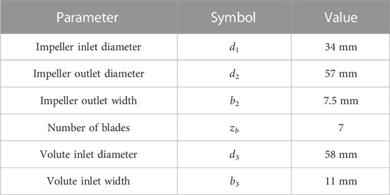
TABLE 1. Main structural parameters of ECP.
This study employs a numerical simulation approach to investigate the impacts of different suction pipe structures on the hydraulic performance and internal flow field of ECP. Three designated suction pipe configurations, denoted as Case A, Case B, and Case C, are devised for examination. Case A features a straight pipe positioned directly opposite the impeller inlet, providing optimal inflow conditions, as illustrated in Figure 1A. In Case B, the suction pipe is inclined at an angle of 30° to the plane of the impeller inlet and connected through a bend, as depicted in Figure 1B. Case C extends the design by incorporating two manifolds in the foundation of Case B, with three pipes intersecting at the bend. This configuration is primarily tailored to address the cooling and heat dissipation requirements of different components simultaneously, as shown in Figure 1C. In this setup, the main pipe has a diameter of 34 mm, while Manifolds A and B have diameters of 14 mm and 12 mm, respectively.
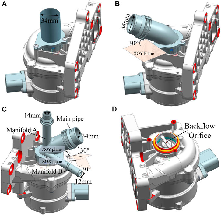
FIGURE 1. Three-dimensional model of ECP. (A) Case A; (B) Case B; (C) Case C; (D) The location of backflow orifice.
Furthermore, a backflow orifice is strategically positioned at the impeller inlet, establishing a connection between the impeller inlet and the rear chamber through the hollow shaft. This configuration facilitates the dissipation of heat originating from the motor and PCB. The precise location of the backflow orifice is illustrated in Figure 1D.
2.2 Computational mesh
Figure 2 displays the mesh configuration for ECP. Critical hydraulic components, such as the impeller and volute, are discretized using hexahedral meshes with incorporated boundary layers. (Cui et al., 2021; Deng, 2024). Simultaneously, tetrahedral meshes are applied to the remaining components. This hybrid meshing approach strikes a balance between computational accuracy and meshing cost (Liu et al., 2015), rendering it well suited for the numerical simulation of intricate fluid machinery.
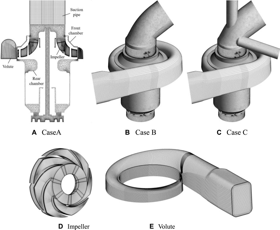
FIGURE 2. Hybrid mesh. (A) Case A; (B) Case B; (C) Case C; (D) impeller; (E) volute.
Figure 3 depicts the correlation between the cell number in Case A and the hydraulic performance of ECP. Six cell numbers, namely, 1.97 million, 3.39 million, 4.91 million, 6.64 million, 8.23 million, and 9.57 million, are employed in the assessment. It is observed that, at the cell number of 4.91 million, the efficiency and pressure rise exhibit a consistent trend. Hence, in light of considerations regarding computational accuracy and efficiency, a cell number of 6.64 million is selected for the numerical calculations.
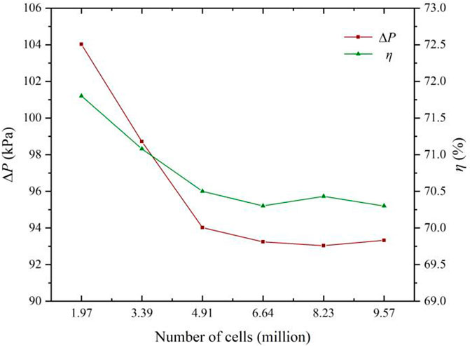
FIGURE 3. Mesh independence.
2.3 Computational setup
The numerical simulations of ECP are conducted utilizing the compressible Reynolds-averaged Navier–Stokes (RANS) equations, coupled with the shear stress transport k–ω turbulence model, and incorporating temperature calculations. These simulations are carried out using Ansys CFX commercial software (Gu et al., 2022). The continuity equation and momentum equation are expressed in Eqs 1, 2:
where t is the time, x stands for the coordinate, u represents the velocity, and p denotes the pressure.
In the energy conservation equation, the effects of pressure, dissipation, and heat source are considered as shown in Eq. 3:
where T is the temperature, μeff denotes the effective viscosity, Cp is the constant pressure specific heat capacity, λeff represents the effective thermal conductivity, Φ stands for dissipation, and S is the heat source. Subscripts i and j indicate the directions.
In the setup of boundary conditions, all cases are configured with a mass flow rate inlet and a total pressure outlet set at 1.5 bar. Uniform total flow rates are maintained for all cases, with Case C distributing the flow rate based on the pipe cross-sectional area. The mass flow rate inlet coolant temperature for Cases A and B is established at 358 K, while the inlet coolant temperature for the main pipe of Case C is also set to 358 K; however, for the manifolds, it is set to 398 K. The thermal flux intensities on the motor and PCB heat dissipation surfaces are specified as 16,211.5 W m2 and 22,556.4 W m2, respectively. The remaining walls are configured as adiabatic and non-slip. The relationship between coolant physical properties and temperature is modeled using the CFX Expression Language embedded in Ansys CFX, with the fitting equations detailed in Table 2.
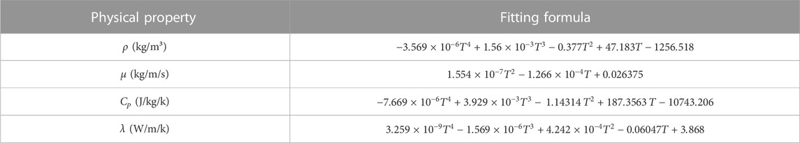
TABLE 2. Relationship between coolant properties and temperature.
The interface between the rotating and stationary components is configured as a frozen rotor for steady simulations and a transient frozen rotor for unsteady simulations. The accuracy and stability of the numerical calculations are contingent upon the Courant–Friedrichs–Lewy number, which is meticulously maintained at approximately 5 throughout the calculations (Lu et al., 2023). For unsteady calculations, the convergence residual is set at 10–4, and the time step corresponds to the duration required for a 3° rotation of the impeller, totaling 6 cycles of impeller rotation. The final result used for analysis is the average of the outcomes from the last revolution of the calculation.
3 Experimental setup and validation
3.1 Experimental setup
The experimental setup for assessing the efficiency and pressure rise of ECP is illustrated in Figure 4. The experimental bench primarily comprises a test pump, an auxiliary pump, a pressure sensor, a flowmeter, a tank, a tachometer, and a wattmeter. Notably, the tank serves the purpose of heating the coolant and maintaining a constant temperature. The measurement errors for the pressure sensor, flowmeter, tachometer, and wattmeter are specified as 0.1%, 0.3%, 0.1%, and 0.1%, respectively. The pump performance characteristics are computed following the procedures outlined by Johann Friedrich Gülich (2008), and the experiment is conducted in triplicate to mitigate experimental errors and ensure result accuracy. The uncertainties associated with pressure rise and efficiency do not exceed 0.17% and 0.35%, respectively.
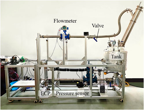
FIGURE 4. ECP test bench.
In the experiment, the pressure rise is computed based on the differential between inlet and outlet pressures, while the efficiency is determined using Eq. 4:
where Pi represents the input power of the ECP rotor.
3.2 Comparisons of hydraulic performance
The pressure rise and efficiency of Case A are tested in the experiments, and the comparison of the experimental and simulation results is shown in Figure 5. Experimentally, the optimum efficiency reached 64.95%, corresponding to a pressure rise of 87.34 kPa. In numerical simulations, the highest efficiency occurs at Qd, registering at 70.3%, with a pressure rise of 93.24 kPa. The experimentally obtained optimal efficiency is 5.35% lower than that of the numerical simulation, with the pressure rise being 0.063% lower. These disparities are attributed to external factors such as tube resistance and measurement errors influencing the experiments. However, despite the differences, the performance curve derived from the numerical simulation exhibits a congruent trend with the experimental data, affirming the accuracy of the numerical simulation method.
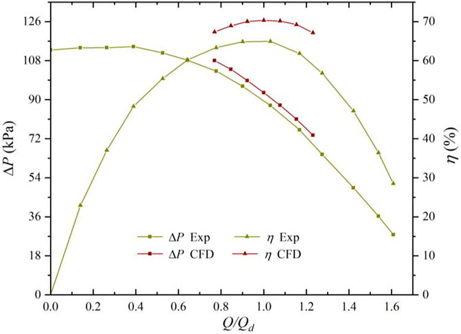
FIGURE 5. Comparison of experimental and simulation results for Case A.
4 Results and discussion
4.1 Analysis of performance
The pump performance and internal flow field characteristics derived from unsteady simulation exhibit closer alignment with experimental results than those obtained through steady simulation (Kim et al., 2019). The hydraulic performance of ECP under different conditions is determined through unsteady simulation, as illustrated in Figure 6.
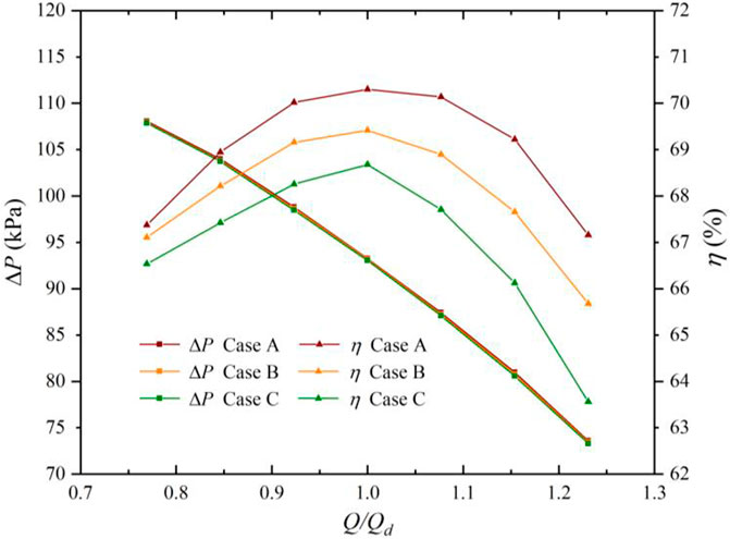
FIGURE 6. Hydraulic performance under different cases.
For equivalent flow rates, transitioning from Case A to Case C led to a significant decrease in efficiency, while the pressure rise exhibits only a marginal reduction. At 0.769Qd, Case A demonstrates a pressure rise of 108.1 kPa with an efficiency of 67.37%, Case B records a pressure rise of 107.94 kPa, achieving 67.1% efficiency, and Case C yields a pressure rise of 107.85 kPa with 66.53% efficiency. At Qd, Case A exhibits a pressure rise of 93.24 kPa with an efficiency of 70.3%, Case B shows a pressure rise of 93.16 kPa with 69.42% efficiency, and Case C results in a pressure rise of 93.04 kPa with 68.68% efficiency. At 1.231Qd, Case A displays a pressure rise of 73.60 kPa with 67.16% efficiency, Case B presents a pressure rise of 73.45 kPa with 65.68% efficiency, and Case C showcases a pressure rise of 73.30 kPa with 63.56% efficiency.
On the other hand, when transitioning from Case A to Case C, efficiency experiences a more pronounced decline at elevated flow rates. Specifically, at 0.769Qd, Case A surpasses Cases B and C in efficiency by 0.27% and 0.84%, respectively. At Qd, Case A exhibits higher efficiency than Cases B and C by 0.88% and 1.62%, respectively. Moreover, at 1.231Qd, Case A outperforms Cases B and C with superiority in efficiency of 1.48% and 3.6%, respectively.
In general, the efficiency of Cases B and C exhibits an average reduction of 1.18% and 2.13%, respectively, compared to Case A, while the pressure rise demonstrates marginal decreases of 0.0016% and 0.0032% within the studied flow rate ranges. The suction pipe structure notably impacts ECP efficiency but has almost negligible effects on pressure rise. The underlying reasons for this phenomenon will be analyzed subsequently.
4.2 Analysis of streamline
The ECP suction pipe structure plays a crucial role in influencing the flow pattern at the impeller inlet, with bends and manifolds impacting the inflow pattern and contributing to increased flow losses (Zhang and Li, 2018). The streamlines for all cases at the design flow rate are depicted in Figure 7.
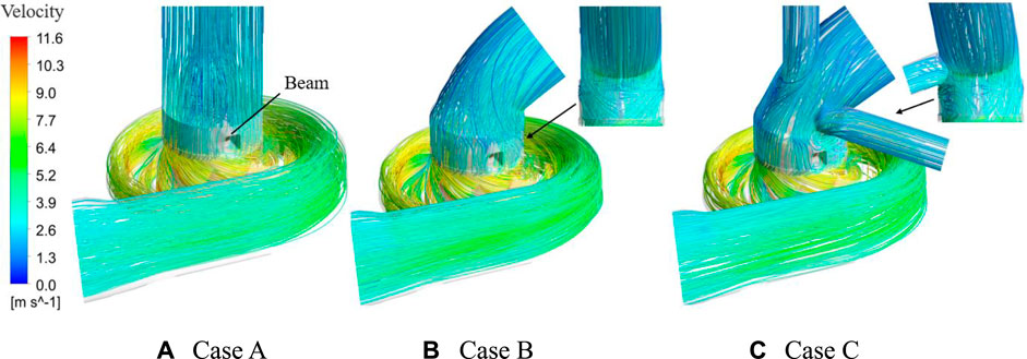
FIGURE 7. Streamlines for different cases at Qd. (A) Case A; (B) Case B; (C) Case C.
In general, Case A exhibits the most favorable flow pattern, whereas Case C displays the least favorable. The cooling backflow in ECP is characterized by a pressure-driven flow, generating a jet as it exits the backflow orifice and colliding with the inflow from the suction pipe, thereby disrupting the streamlines. In Case A, the influence of the jet from the backflow orifice intertwines the streamlines in the middle of the pipe, causing a disturbance in the flow pattern. However, other zones maintain smooth and straight streamlines with a favorable flow pattern. The jet has no impact on the impeller inlet flow pattern, resulting in the highest efficiency. When the suction pipe is configured as a bend, the velocity on the outside of the bend surpasses that on the inside, creating a pressure gradient that induces secondary flow generation (Zhang et al., 2022). Simultaneously, the jet collides with the main flow, disrupting the flow pattern and increasing flow losses, leading to a reduction in the efficiency of Case B. In Case C, a circular cylinder flow manifests at the outlet of Manifold A, and the evident occurrence of flow separation is observed. The outflow from Manifold B is influenced by the inflow from the main pipe, inducing heightened disorder in the secondary flow streamlines and markedly impacting the impeller inlet flow pattern. This exerts the most substantial influence on efficiency, culminating in the lowest attainable efficiency.
The corresponding streamlines for Case C at different flow rates are shown in Figure 7C and Figure 8. The pipe streamlines are basically the same for each flow rate, but the disordered flow caused by the jet impact is not the same. The driving pressure of backflow is the pressure difference between the impeller inlet and outlet, and it is largest when the flow rate is 0.769Qd, corresponding to the highest jet intensity, resulting in the most disordered flow pattern. In addition, as the flow rate increases, the secondary flow on the inside of the bend becomes much more serious. This is because the velocity difference between the inside and outside of the bend increases with the flow rate, and the pressure gradient becomes larger, enhancing the secondary flow.
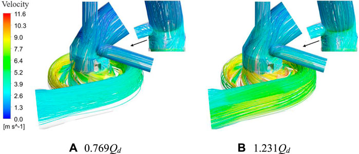
FIGURE 8. Streamlines of Case C at different flow rates. (A) 0.769Qd; (B) 1.231Qd.
4.3 Analysis of temperature
In this section, the influences of suction pipe structures on the temperature distribution of ECP is investigated. The temperature distribution corresponding to different suction pipe structures at Qd is depicted in Figure 9. Due to the integration of electronic components, the PCB surface exhibits unevenness, leading to non-uniform heat dissipation. Consequently, noticeable local high temperatures are observed on PCB in each case, and the overall temperature surpasses that of the motor.
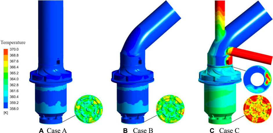
FIGURE 9. Temperature distribution for different cases at Qd. (A) Case A; (B) Case B; (C) Case C.
The temperature distribution on the motor heat dissipation surface is generally consistent between Cases A and B. However, in Case B, the local temperature of PCB is marginally higher than that of Case A. For Case C, the temperatures of the manifolds and main pipe differ, and they become more uniform after mixing by the impeller. Nevertheless, it still remains approximately 2.5 K higher than in the other cases, resulting in a weakening of the heat transfer effect. Consequently, the temperatures of the motor and PCB are higher.
Figure 9C and Figure 10 illustrate the temperature distribution of Case C at different flow rates. With an increase in the flow rate, the motor temperature experiences a slight rise, while the local temperature of PCB increases significantly. As the flow rate increases, the impeller inlet temperature mixing diminishes, causing the expansion of the high-temperature zones. Simultaneously, the coolant temperature in the impeller exhibits reduced mixing, leading to noticeable stratification and an overall temperature increase. Consequently, the motor temperature increases as the coolant enters the rear chamber. The reduction in heat transfer efficiency is attributed to the higher thermal flux intensity on the heat dissipating surface of PCB and the prior absorption of heat from the motor by coolant-flowing PCB, yielding a heightened temperature. Subsequently, the temperature rise is notably more pronounced in PCB in contrast to the motor. Hence, PCB is relatively more vulnerable to thermal damage. In the process of optimizing the heat dissipation of ECP, particular attention is given to the thermal management of PCB.
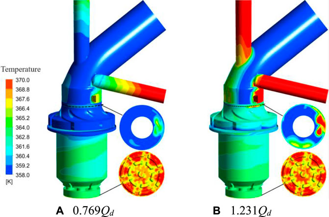
FIGURE 10. Temperature distribution of Case C at different flow rates. (A) 0.769Qd; (B) 1.231Qd.
4.4 Analysis of vorticity
Upon analysis of Section 4.2, it is observed that a pressure gradient manifests as the fluid traverses the bend. Notably, two bundles of secondary flow exhibiting relative motion occur on the inner side of the bend, converging in the midpoint of the inner side. This convergence leads to a significant alteration in flow direction, causing a pronounced curling of streamlines and the generation of a vortex (Zuojun et al., 2016). Vorticity is employed to characterize vortex strength and can be visualized in CFD-Post (Zhang et al., 2019). In this section, the vorticity distribution is analyzed for different suction pipe structures. The vorticity distribution of the cross section of ECP at Qd is illustrated in Figure 11.
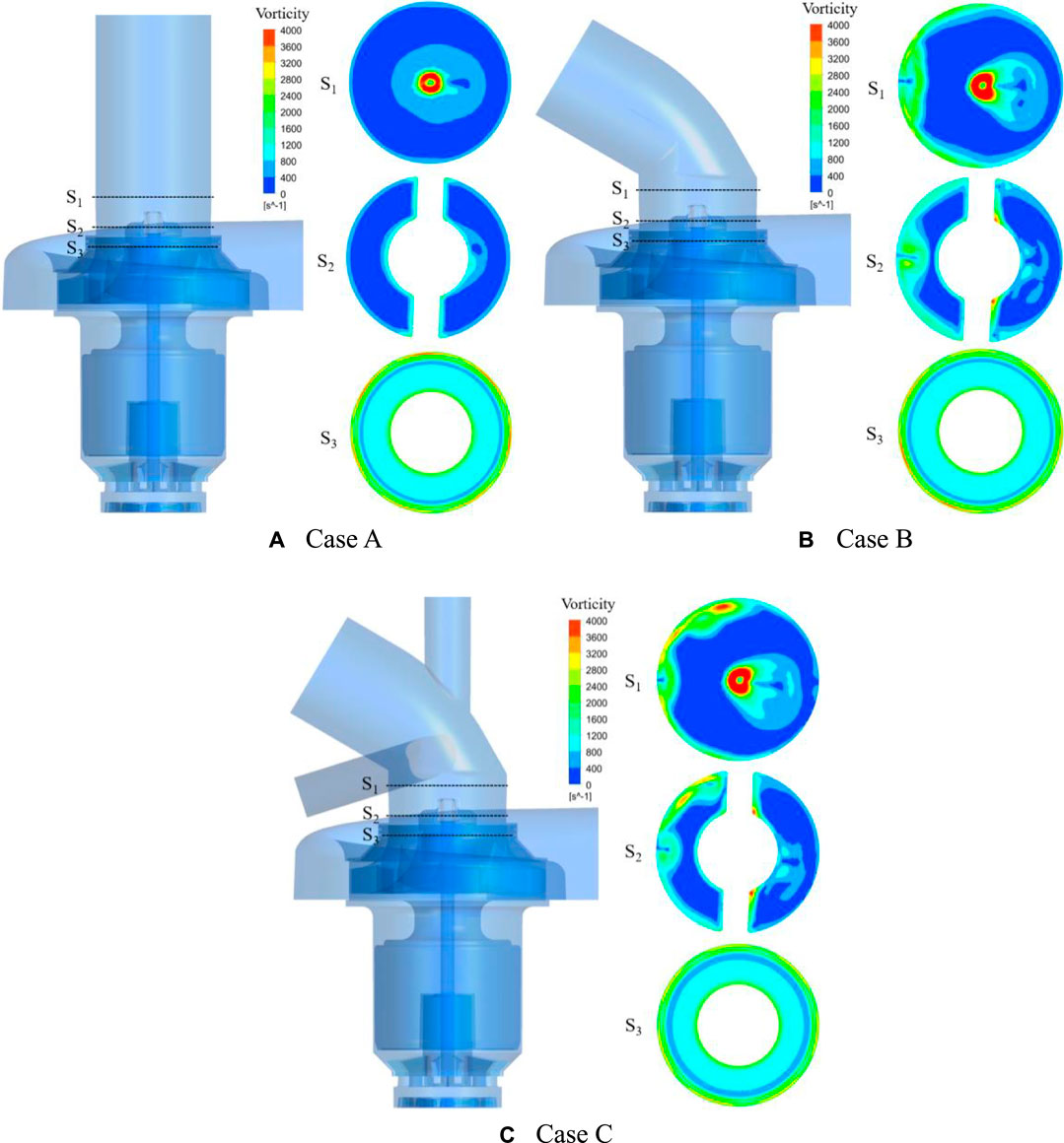
FIGURE 11. Vorticity distribution for different cases at Qd. (A) Case A; (B) Case B; (C) Case C.
The suction pipe structure significantly influences the vorticity distribution in the pump. At S1, the backflow orifice jet collides with the main flow, creating a high-intensity vortex (Zong and Kotsonis, 2020). The high-vorticity zone is the smallest in Case A and the largest in Case C. As depicted in Figure 7, the high-vorticity zones emerge at the bend of Case B due to the secondary flow generation. In Case C, the outflow from Manifold B interacts with the inflow from the main pipe, intensifying the secondary flow and increasing the vorticity at the Manifold B outlet.
At S2, Case A continues to exhibit the lowest vorticity. In Cases B and C, the vorticity distribution caused by the bend and jet is essentially identical. However, the outflow from Manifold B in Case C generates high-vorticity zones. Consequently, when compared, the vorticity in Case C is highest at S2.
S3 is situated at the impeller inlet, where the rotation of the impeller induces significant shear stresses and high-vorticity zones close to the wall. In Case A, the high-vorticity zones are uniformly distributed, slightly reduced in Case B, and minimized in Case C. In Case B, the disordered streamlines influence the impeller inlet flow pattern, resulting in an uneven vorticity distribution in S3. When compared to Case A, the coolant temperature is higher in Case C, and the decreased viscosity leads to a weakened wall shear effect, resulting in the smallest high-vorticity zones.
In summary, Case C exhibits the highest vorticity, while Case A has the lowest. The generation of vortices is frequently coupled with turbulence, leading to turbulence losses (Deng et al., 2023; Kan et al., 2023). Furthermore, the vortex introduces additional resistance and increases flow friction, contributing to reduced efficiency. Conversely, pressure rise is primarily associated with the pump geometrical parameters, explaining the significant variations in efficiencies depicted in Figure 6, while the pressure rise remains essentially constant.
Figure 11C and Figure 12 illustrate the vorticity distribution for Case C at different flow rates. With the increase in flow rates, the vorticity intensifies. Despite the diminishing intensity of the backflow jet with increased flow rates, the augmented inflow from the pipe extends the reach of the jet influence. Concurrently, the augmentation in flow intensifies the secondary flow, resulting in an elevation of S1 and S2 vorticities. Analogously, the domain influenced by the shear stress induced by the rotation of the impeller inlet wall expands following the increase in flow rate, thereby causing an escalation in S3 wall vorticity.
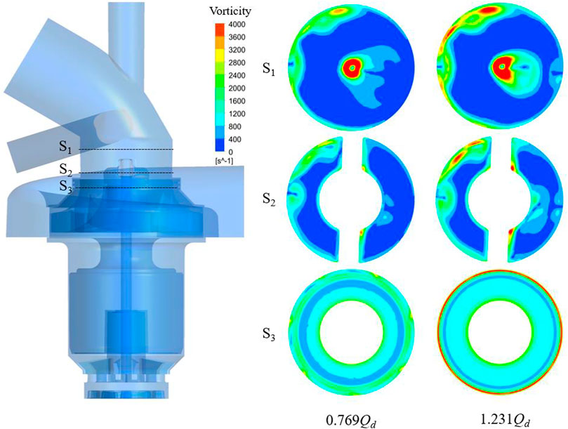
FIGURE 12. Vorticity distribution of Case C at different flow rates.
5 Conclusion
In this study, the effects of three suction pipe structures on the hydraulic performance, temperature distribution, flow pattern, and vorticity of ECP are examined through numerical simulations. The experimental and numerical simulation results are in good agreement. The conclusions are as follows:
(1) The suction pipe structure exerts a notable impact on the efficiency of ECP, with minimal influence on the pressure rise. Compared to Case A, the average efficiency declined by 1.18% for Case B and 2.13% for Case C. Similarly, the average pressure rise experiences a reduction of 0.002% for Case B and 0.003% for Case C.
(2) The suction pipe structure has a small effect on the heat dissipation of ECP. The uneven surface of PCB produces high localized temperatures. Coolant temperature has a significant effect on ECP heat dissipation. The motor and PCB temperatures in Case C are significantly higher than those in other cases. The motor and PCB temperatures increase slightly when the flow rate is increased.
(3) Streamlines illustrate that Case A, with a straight suction pipe, exhibits the optimal flow pattern, while Case C, incorporating manifolds, displays the least favorable flow pattern. Secondary flow is induced on the interior of the bend in Case B and is further intensified by Manifold B in Case C. The flow pattern experiences increased disorder with increasing flow rates. As the flow rate increases, the secondary flow within the bend intensifies, resulting in a more disordered flow pattern.
(4) The vorticity analysis reveals that Case A exhibits the lowest vorticity, while Case C demonstrates the highest vorticity. Higher vorticity is observed on the inside of the bend, and Manifold B further enhances the vorticity in this zone. Vorticity intensifies with an increase in the flow rate.
Data availability statement
The original contributions presented in the study are included in the article/supplementary material; further inquiries can be directed to the corresponding author.
Author contributions
AY: writing–original draft, writing–review and editing, formal analysis, investigation, and software. YG: writing–original draft, writing–review and editing, conceptualization, funding acquisition, methodology, project administration, and supervision. LC: writing–review and editing. WZ: writing–review and editing.
Funding
The author(s) declare that financial support was received for the research, authorship, and/or publication of this article. This work was supported by the National Natural Science Foundation of China (Grant No. 52206055), Natural Science Fund for Colleges and Universities in Jiangsu Province, China (Grant No. 22KJB570005), Postdoctoral Research Fund of Jiangsu Province, China (Grant No. 2021K569C), Science and Technology Project of Yangzhou City, China (Grant No. YZ2022204), Priority Academic Program Development of Jiangsu Higher Education Institutions (PAPD).
Conflict of interest
The authors declare that the research was conducted in the absence of any commercial or financial relationships that could be construed as a potential conflict of interest.
Publisher’s note
All claims expressed in this article are solely those of the authors and do not necessarily represent those of their affiliated organizations, or those of the publisher, the editors, and the reviewers. Any product that may be evaluated in this article, or claim that may be made by its manufacturer, is not guaranteed or endorsed by the publisher.
References
AhmedAl-Obaidi, R. (2021). Numerical investigation on effect of various pump rotational speeds on performance of centrifugal pump based on CFD analysis technique. Int. J. Model. Simul. Sci. Comput. 12 (5), 2150045. doi:10.1142/s1793962321500458
Bai, Y., Appiah, D., and Yi, T. (2022). Computational turbulent flow characteristics in a centrifugal pump. AIP Adv. 12 (7), 075025. doi:10.1063/5.0100915
Cheng, X., Wang, P., and Zhang, S. (2021). Correlation Research between turbulent pressure pulsation and internal sound field characteristics of centrifugal pump. J. Therm. Sci. 30 (1), 100–110. doi:10.1007/s11630-020-1253-y
Cui, B., Zhu, K., Zhang, Y., and Lin, P. (2019). Experimental and numerical study of the performance and cavitation flow of centrifugal pump with jetting device. J. Mech. Sci. Technol. 33 (10), 4843–4853. doi:10.1007/s12206-019-0925-6
Cui, D., Guo, C., Ge, Z., Liu, H., and Dong, L. (2021). Study on drag and noise reduction of bionic blade of centrifugal pump and mechanism. J. Bionic Eng. 18 (2), 428–440. doi:10.1007/s42235-021-0021-3
Deng, X. (2024). A mixed zero-equation and one-equation turbulence model in fluid-film thrust bearings. Journal of Tribology 146 (3), 034101. doi:10.1115/1.4063945
Deng, X., Harrison, G., Roger, F., and Houston, W. (2019). Methodology of turbulence parameter correction in water-lubricated thrust Bearings. ASME. Journal Fluids Engineers 141 (7), 071104. doi:10.1115/1.4042161
Deng, Q., Pei, Ji, Wang, W., and Sun, Ju (2023). Investigation of energy dissipation mechanism and the influence of vortical structures in a high-power double-suction centrifugal pump. Phys. Fluids 35 (7), 075147. doi:10.1063/5.0157770
Ding, H., Ge, F., Wang, K., and Lin, F. (2023). Influence of blade trailing-edge filing on the transient characteristics of the centrifugal pump during startup. Processes 11 (8), 2420. doi:10.3390/pr11082420
Dong, W., Fan, X., Dong, Y., and Fan, He (2023). Transient Internal Flow Characteristics of centrifugal pump during rapid start-up. Iran. J. Sci. Technol. Trans. Mech. Eng. doi:10.1007/s40997-023-00694-2
Fecser, N., and Lakatos, I. (2021). Cavitation measurement in a centrifugal pump. Acta Polytech. Hung. 18 (4), 63–77. doi:10.12700/aph.18.4.2021.4.4
Feng, J., Ge, Z., Zhang, Yu, Zhu, G., Wu, G., Lu, J., et al. (2021). Numerical investigation on characteristics of transient process in centrifugal pumps during power failure. Renew. Energy 170, 267–276. doi:10.1016/j.renene.2021.01.104
Gu, Y., Bian, J., Wang, C., Sun, H., Wang, M., and Ge, J. (2023). Transient numerical investigation on hydraulic performance and flow field of multi-stage centrifugal pump with floating impellers under sealing gasket damage condition. Phys. Fluids 35 (10), 107123. doi:10.1063/5.0168227
Gu, Y., Cheng, J., Wang, P., Cheng, Li, Qiaorui, Si, Wang, C., et al. (2022). A flow model for side chambers of centrifugal pumps considering radial wall shear stress. Proc. Institution Mech. Eng. Part C J. Mech. Eng. Sci. 236 (13), 7115–7126. doi:10.1177/09544062211073023
Gu, Y., Sun, H., Wang, C., Lu, R., Liu, B., and Ge, J. (2024). Effect of trimmed rear shroud on performance and axial thrust of multi-stage centrifugal pump with emphasis on visualizing flow losses. J. Fluids Eng. 146 (1), 011204. doi:10.1115/1.4063438
Guo, Y., Yang, C., Wang, Y., Lv, T., and Zhao, S. (2022). Study on inlet flow field structure and end-wall effect of axial flow pump impeller under design condition. Energies (Basel). 15 (14), 4969. doi:10.3390/en15144969
Jia, X., Yu, Y., Bo, Li, Wang, F., and Zhu, Z. (2023). Effects of incident angle of sealing ring clearance on internal flow and cavitation of centrifugal pump. Proc. Institution Mech. Eng. Part E J. Process Mech. Eng., 095440892311696. doi:10.1177/09544089231169617
Jiang, J., Li, Y., Pei, C., Li, L., Fu, Y., Cheng, H., et al. (2019). Cavitation performance of high-speed centrifugal pump with annular jet and inducer at different temperatures and void fractions. J. Hydrodynamics 31, 93–101. doi:10.1007/s42241-019-0011-7
Kan, K., Zhao, F., Xu, H., Feng, J., Chen, H., and Liu, W. (2023). Energy performance evaluation of an axial-flow pump as turbine under conventional and reverse operating modes based on an energy loss intensity model. Phys. Fluids 35 (1), 015125. doi:10.1063/5.0132667
Kim, J.-H., Cho, B.-M., Kim, S., Lee, Y.-K., and Choi, Y.-S. (2019). Steady and unsteady flow characteristics of a multi-stage centrifugal pump under design and off-design conditions. Int. J. Fluid Mach. Syst. 12 (1), 64–70. doi:10.5293/ijfms.2019.12.1.064
Kumar Samal, S., and Moharana, M. K. (2021). Effects of inlet/outlet manifold configuration on the thermo-hydrodynamic performance of recharging microchannel heat sink. J. Therm. Sci. Eng. Appl. 13. doi:10.1115/1.4047940
Leilei, Ji, Li, W., Shi, W., and RameshAgarwal, K. (2021). Application of wray-agarwal turbulence model in flow simulation of a centrifugal pump with semispiral suction chamber. J. Fluids Eng. 143 (3), 143. doi:10.1115/1.4049050
Li, D., Zhang, N., Jiang, J., Gao, Bo, Zhou, W., Shi, J., et al. (2022). Numerical investigation on the unsteady vortical structure and pressure pulsations of a centrifugal pump with the vaned diffuser. Int. J. Heat Fluid Flow 98, 109050. doi:10.1016/j.ijheatfluidflow.2022.109050
Li, W., Huang, Y., Leilei, Ji, Ma, L., RameshAgarwal, K., and Awais, M. (2023b). Prediction model for energy conversion characteristics during transient processes in a mixed-flow pump. Energy 271, 127082. doi:10.1016/j.energy.2023.127082
Li, W., Leilei, Ji, Shi, W., Li, E., Ma, L., and Yang, Z. (2020). Particle image velocimetry experiment of the inlet flow field in a mixed-flow pump during the startup period. Proc. Institution Mech. Eng. Part A J. Power Energy 234 (3), 300–314. doi:10.1177/0957650919857425
Li, W., Liu, M., Leilei, Ji, Li, shuo, Song, R., Wang, C., et al. (2023a). Study on the trajectory of tip leakage vortex and energy characteristics of mixed-flow pump under cavitation conditions. Ocean. Eng. 267, 113225. doi:10.1016/j.oceaneng.2022.113225
Li, W., Wu, Pu, Yang, Y., Shi, W., and Li, W. (2021). Investigation of the cavitation performance in an engine cooling water pump at different temperature. Proc. Institution Mech. Eng. Part A J. Power Energy 235, 1094–1102. doi:10.1177/0957650920984646
Li, Z., Ding, H., Xiao, S., and Jiang, Y. (2019). Performance optimization of high specific speed centrifugal pump based on orthogonal experiment design method. Processes 7 (10), 728. doi:10.3390/pr7100728
Lin, Y., Li, X., Zhu, Z., Wang, X., Tong, L., and Cao, H. (2022). An energy consumption improvement method for centrifugal pump based on bionic optimization of blade trailing edge. Energy 246, 123323. doi:10.1016/j.energy.2022.123323
Liu, H., Liu, M., Bai, Yu, and Dong, L. (2015). Effects of mesh style and grid convergence on numerical simulation accuracy of centrifugal pump. J. Central South Univ. 22, 368–376. doi:10.1007/s11771-015-2531-9
Liu, S., Zhuge, W., and Zhang, Y. (2021). Numerical and experimental investigation of exhaust manifold configurations of turbo-charged diesel engines. Proc. Institution Mech. Eng. Part A J. Power Energy 235, 1119–1130. doi:10.1177/0957650920970307
Lu, J., Gong, Y., Li, L., Liu, X., Kan, N., Zhang, F., et al. (2023). Investigation of pressure pulsation induced by quasi-steady cavitation in a centrifugal pump. Phys. Fluids 35 (4), 045144. doi:10.1063/5.0135095
Lu, R., Yuan, J., Wang, L., Fu, Y., Hong, F., and Wang, W. (2021). Effect of volute tongue angle on the performance and flow unsteadiness of an automotive electronic cooling pump. Proc. Institution Mech. Eng. Part A J. Power Energy 235 (2), 227–241. doi:10.1177/0957650920915306
Lv, J., Xu, W., Yin, H., Zhang, Y., and Dou, H. (2022). Numerical simulation of the internal flow stability in a centrifugal pump with high specific speed at partial load. Iran. J. Sci. Technology-Transactions Mech. Eng. 46, 1245–1260. doi:10.1007/s40997-021-00468-8
Minocha, N., and JyeshtharajJoshi, B. (2020). 3D CFD simulation of turbulent flow distribution and pressure drop in a dividing manifold system using openfoam. Int. J. Heat Mass Transf. 151, 119420. doi:10.1016/j.ijheatmasstransfer.2020.119420
Nishi, Y., and Noji, T. (2020). Flow structure in casing of closed-type centrifugal pump with single blade. Int. J. Fluid Mach. Syst. 13 (1), 114–125. doi:10.5293/ijfms.2020.13.1.114
Qi, H., Li, W., Leilei, Ji, Liu, M., Song, R., Pan, Y., et al. (2023). Performance optimization of centrifugal pump based on particle swarm optimization and entropy generation theory. Front. Energy Res. 10. doi:10.3389/fenrg.2022.1094717
Shi, G., Liu, Z., Xiao, Y., Li, H., and Liu, X. (2021). Velocity characteristics in a multiphase pump under different tip clearances. Proc. Institution Mech. Eng. Part A J. Power Energy 235 (3), 454–475. doi:10.1177/0957650920946533
Wang, C., Chen, X., Ge, J., Cao, weidong, Zhang, qiqi, Zhu, yong, et al. (2023). Internal flow characteristics of high-specific-speed centrifugal pumps with different number of impeller blades under large flow conditions. Machines 11 (2), 138. doi:10.3390/machines11020138
Ye, C., Tang, Y., An, D., Wang, F., Zheng, Y., and van Esch, B. P. M. (2023). Investigation on stall characteristics of marine centrifugal pump considering transition effect. Ocean. Eng. 280, 114823. doi:10.1016/j.oceaneng.2023.114823
Yuan, Ye, Jin, R., Tang, L., and Lin, Y. (2022). Optimization design for the centrifugal pump under non-uniform elbow inflow based on orthogonal test and GA_PSO. Processes 10 (7), 1254. doi:10.3390/pr10071254
Yuan, Z., Zhang, Y., Wang, C., and Lu, B. (2021). Study on characteristics of vortex structures and irreversible losses in the centrifugal pump. Proc. Institution Mech. Eng. Part A J. Power Energy 235 (5), 1080–1093. doi:10.1177/0957650920983061
Zeng, G., Li, Q., Wu, P., Qian, Bo, Huang, B., Li, S., et al. (2020). Investigation of the impact of splitter blades on a low specific speed pump for fluid-induced vibration. J. Mech. Sci. Technol. 34 (7), 2883–2893. doi:10.1007/s12206-020-0620-7
Zhang, J., Wang, D., Wang, W., and Zhu, Z. (2022b). Numerical investigation and optimization of the flow characteristics of bend pipe with different bending angles. Processes 10 (8), 1510. doi:10.3390/pr10081510
Zhang, N., Jiang, J., Gao, Bo, Liu, X., and Ni, D. (2020). Numerical analysis of the vortical structure and its unsteady evolution of a centrifugal pump. Renew. Energy 155, 748–760. doi:10.1016/j.renene.2020.03.182
Zhang, N., Liu, X., Gao, Bo, and Xia, B. (2019). DDES analysis of the unsteady wake flow and its evolution of a centrifugal pump. Renew. Energy 141, 570–582. doi:10.1016/j.renene.2019.04.023
Zhang, W., and Li, A. (2018). Resistance reduction via guide vane in dividing manifold systems with parallel pipe arrays (DMS-PPA) based on analysis of energy dissipation. Build. Environ. 139, 189–198. doi:10.1016/j.buildenv.2018.04.010
Zhang, X., Zhao, Li, Luo, L., Fan, Y., and Du, Z. (2022a). A review on thermal management of lithium-ion batteries for electric vehicles. Energy 238, 121652. doi:10.1016/j.energy.2021.121652
Zhao, W., and Guo, B. (2021). Investigations on the effects of obstacles on the surfaces of blades of the centrifugal pump to suppress cavitation development. Mod. Phys. Lett. B 35 (20), 2150327. doi:10.1142/s0217984921503279
Zhi, R., Tang, L., and Zhang, hui (2023). Double-tongue worm shell structure on plastic centrifugal pump performance study. Appl. Sci. 13 (14), 8507. doi:10.3390/app13148507
Zong, H., and Kotsonis, M. (2020). Three-dimensional vortical structures generated by plasma synthetic jets in crossflow. Phys. Fluids 32 (6), 061701. doi:10.1063/5.0009530
Zuojun, W., Qiao, W., Liu, J., and Duan, W. (2016). Reduction of endwall secondary flow losses with leading-edge fillet in a highly loaded low-pressure turbine. Proc. Institution Mech. Eng. Part A J. Power Energy 230 (2), 184–195. doi:10.1177/0957650915619560
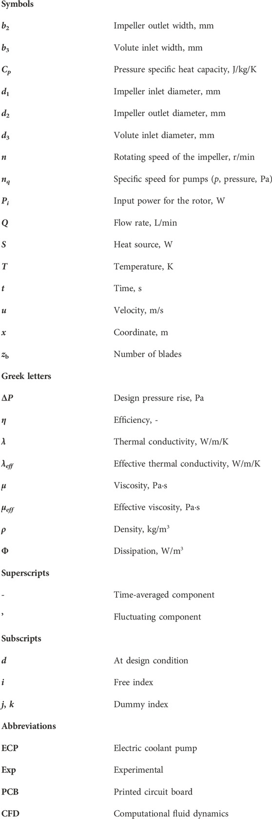
Nomenclature
Keywords: electric coolant pump, numerical simulation, experiment, suction pipe, hydraulic performance, vorticity
Citation: Yang A, Gu Y, Cheng L and Zhao W (2024) Influences of suction pipe structures on hydraulic performance and internal flow of electric coolant pumps. Front. Energy Res. 11:1344186. doi: 10.3389/fenrg.2023.1344186
Received: 25 November 2023; Accepted: 06 December 2023;
Published: 04 January 2024.
Edited by:
Kan Kan, College of Energy and Electrical Engineering, ChinaReviewed by:
Yonggang Lu, Tsinghua University, ChinaJilai Zeng, Lanzhou University of Technology, China
Copyright © 2024 Yang, Gu, Cheng and Zhao. This is an open-access article distributed under the terms of the Creative Commons Attribution License (CC BY). The use, distribution or reproduction in other forums is permitted, provided the original author(s) and the copyright owner(s) are credited and that the original publication in this journal is cited, in accordance with accepted academic practice. No use, distribution or reproduction is permitted which does not comply with these terms.
*Correspondence: Yandong Gu, Z3V5YW5kb25nQHl6dS5lZHUuY24=