 Yu Fan
 Fan Yu
- Engineering Technology Research Institute of PetroChina Southwest Oil and Gas Field Company, Chengdu, China
The accumulation of liquid in gas wells is a common problem in the later stages of shale gas production. The plunger lift is currently one of the most economically effective methods for removing accumulated liquid in gas wells, but its applicability is not yet clear. This article analyzes the production characteristics of gas wells on-site and summarizes the key indicators for evaluating the plunger lift technology, including casing pressure changes, production changes, liquid column plunger height, tubing-casing pressure differential changes, and differential size of pressure relief. Combined with numerical simulation methods, a complete set of evaluation systems for judging, classifying, and evaluating the effectiveness of plunger lift technology is established, and an evaluation method for the applicability of plunger lift technology is proposed. Taking well Ning 216-H4 as an example, a comprehensive evaluation is made on whether the gas well is suitable for plunger lift based on the height of the liquid column above the plunger, the production effect under pressure, and the overall shut-in time. This method has important guiding significance for the further promotion and application of plunger lift technology in deep wells, directional wells, and horizontal wells to achieve efficient development of natural gas.
1 Introduction
Shale gas wells are characterized by low porosity and low permeability, necessitating volume fracturing for industrial gas flow initiation. Given the difficulty in recovering a large volume of fracturing fluid (Meng et al., 2023a), it is assumed that shale gas wells will produce a certain amount of injected water (Zou et al., 2021; Meng et al., 2023b). In the initial production stage, shale gas wells often have high output, but most wells experience a rapid decline in production of 40%–80% within a year (Oyewole, 2016). The production characteristics of high initial output and rapid decline post-fracturing necessitate the use of artificial lift techniques (Kaisare et al., 2013). For low-producing shale gas wells in the middle and late stages of production, plunger lift can achieve optimal economic benefits (HASSOUNA, 2013).
The plunger lift is currently one of the most economically effective methods for removing accumulated liquid in gas wells (Chen et al., 2021), but its applicability is not yet clear (Hassouna, 2013; Hingerl et al., 2020), and there are still some challenges in its application in horizontal wells (Sask et al., 2010).As early as the 1950s, experts and scholars from the United States and the Soviet Union began researching plunger lift. In 1965, Foss and Gaul proposed the classic plunger lift model based on force balance, derived from experience in gas fields, which later influenced most subsequent research (Foss and Gaul, 1965; Lea, 1982). Maggard et al. (2000) established a new dynamic model for plunger lift specifically for tight gas wells, enabling in-depth analysis of the entire gas lift process in such wells. In 2007, plunger lift was applied in 40 tight gas wells in the San Juan Basin’s northern area, resulting in an increase in daily production of over 11 × 104 m3/d (Oyewole and Garg, 2007). Advances in related technologies have greatly expanded the application range of plunger lift technology, especially the rise of gas-assisted-plunger-lift (GAPL) and plunger-assisted-gas lift (PAGL), further extended plunger lift’s capabilities in horizontal wells (Burns, 2018). In 2011, the plunger reached a 74 well inclination in Marcellus shale gas wells, demonstrating the applicability of plunger lift in horizontal wells (Kravits et al., 2011).
Currently, there is limited research on comprehensive evaluation methods for plunger lift in the industry. Lea et al. (2007) proposed an empirical method for monitoring plunger movement, liquid column height, and circulation time, optimizing the control parameters of plunger lift. Bello et al. (2011) developed a simple analysis model for plunger lift systems, assessing the feasibility of the technology. Hosein and Mohammed, (2017) used the Foss and Gaul model to determine optimal plunger rise speed and gas requirements. Teymourifar and Ozturk (2018) adopted a neural network heuristic algorithm to solve the production scheduling problem of plunger lift. Liu et al. (2020) proposed a method to implement a work system according to the average production of plunger lift Wells. Yang et al. (2022) established an evaluation method of plunger lift application timing, process parameters, and operational regimes in the shenmu Gas Field based on the production situation.
As an economically effective measure for stabilizing production, the plunger lift has been extensively implemented in over 200 wells in Changning Block (Wang et al., 2023). However, challenges remain, including the dispersion of Plunger lift wells, and a lack of comprehensive evaluation methods. Current practices involve adjusting process parameters based on individual well production without a complete plunger lift applicability evaluation system. Therefore, it is necessary to carry out comprehensive evaluations of plunger lift. This paper summarizes key evaluation indicators for plunger lift based on field production situations, classifies typical field plunger lift wells, and comprehensively evaluates the effectiveness of plunger lift in gas wells.
2 Factors influencing plunger lift
Plunger lift propels the plunger up and down, utilizing the well’s own energy to expel accumulated liquids and prolong the life of the gas well, thereby effectively restoring gas production. This method is a special form of intermittent gas lifting, primarily powered by formation energy, but can be supplemented by injecting high-pressure gas into the wellbore. The plunger, acting as a solid interface, separates the accumulated liquids above from the gas below, reducing liquid loss and gas channeling, thus improving operational efficiency. Typically, the entire movement process of plunger lift is divided into four stages: plunger descent, pressure recovery, plunger ascent, and sustained production (Zhao et al., 2021; Xiong et al., 2023) as shown in Figure 1.
(a) Plunger descent
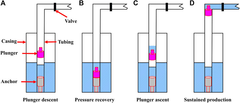
FIGURE 1. Four stages of plunger movement.
After the end of the sustained production stage, the well is shut in, and the plunger starts to descend from the wellhead under its own gravity. The casing pressure and tubing pressure gradually recover, and the plunger passes through the gas and accumulated liquid, eventually descending to the catcher position. If the pressure recovery meets the requirements at this point, the well is reopened to start a new cycle, otherwise, it enters the pressure recovery stage.
(b) Pressure recovery
When the reservoir’s liquid and gas supply capacity is low, the plunger should remain on the catcher for a period, allowing the pressure to recover sufficiently to push the plunger from the wellbore to the wellhead. During this stage, oil and gas continue to accumulate around the wellbore, and the energy at the bottom of the well gradually recovers.
(c) Plunger ascent
When the casing pressure and tubing pressure recovers to a certain extent, the well is opened for production. The expanded gas in the annulus flows into the tubing, lifting the plunger and the upper liquid column towards the wellhead along with the formation gas until the plunger reaches the wellhead, where it is captured by the wellhead catcher. The liquid column above the plunger completely enters the production pipeline, and the gas well enters the continuous sustained production stage.
(d) Sustained production
If the reservoir has sufficient energy, the gas well can be put on intermittent production for a period of time. However, with the production of the gas well, the formation water and accumulated liquid in the annulus gather at the bottom of the well again, causing the well-bottom flow pressure increases continuously. If the gas well energy cannot carry the liquid, it indicates the end of the working cycle.
Key evaluation indicators for plunger lift include casing pressure changes, production variations, plunger height in the liquid segment, changes in tubing-casing pressure differential, and blowdown differential. These indicators are crucial for classifying and evaluating the performance of typical field plunger wells.
(1) Casing Pressure Change after Shut-In
The cycle gas production of plunger lift wells increases with casing pressure and the duration of sustained flow after reopening. The higher the set opening casing pressure, the longer the shut-in time required for pressure recovery, resulting in a longer lift cycle. This is partly due to the larger volume of gas needed to achieve higher casing pressures and partly because the pressure difference between the well-bottom flow pressure and the formation pressure decreases at higher casing pressures, slowing the recovery rate.
(2) Plunger Ascent Speed
Due to a minimum gap of 1.25 mm between the plunger and the tubing wall, liquid loss occurs. The plunger must reach a certain speed during ascent to effectively seal gas and liquid, known as “velocity sealing”. Numerical simulations indicate that the critical ascent speed to prevent liquid leakage is 3.7 m/s (Han, 2016). If the plunger’s ascent speed is too low, gas channeling increases dramatically, reducing production efficiency. Conversely, too high a speed can cause significant liquid leakage, decreasing lifting efficiency.
When the liquid segment plunger reaches the wellhead, the smaller size of the wellhead pipeline compared to the tubing can delay liquid discharge, creating backpressure. The plunger ascent time is from the moment of opening the well until the tubing backpressure returns to atmospheric pressure as shown in Figure 2.
(3) Plunger Descent Speed
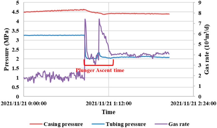
FIGURE 2. Plunger ascent time.
During plunger descent, a dynamic fluid level exists in the tubing, so the plunger experiences both falling through gas and liquid phases. Both too fast and too slow descent speeds are detrimental. For wells with inflection points in the pressure recovery curve, the plunger undergoes both descent and settling in the catcher, with the descent time being from shut-in to the inflection point in the pressure recovery curve. For wells without inflection points: slower plunger descent speeds mean the plunger only experiences the descent phase, with the descent time equal to the shut-in duration as shown in Figure 3.
(4) Tubing-Casing Pressure Differential
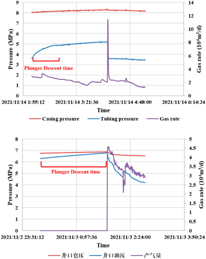
FIGURE 3. Plunger descent time.
For plunger lift wells, one method to judge the effectiveness of plunger lifting is to observe whether there is a height of the liquid column above the plunger. Using data from the Ning 209-2well, a “WellFlo numerical model” was developed to simulate the relationship between tubing-casing pressure differential and liquid column height as shown in Figure 4.
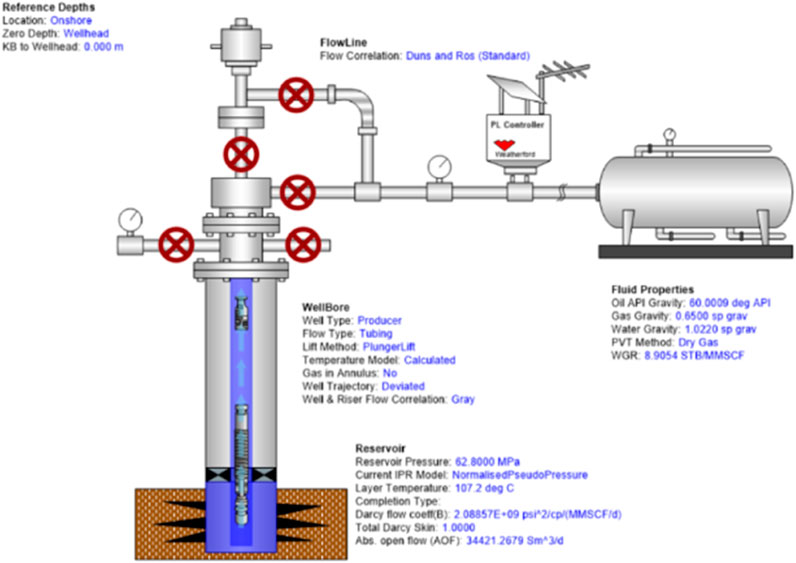
FIGURE 4. WellFlo numerical model.
Results show that the tubing-casing pressure differential reflects the height of the liquid inside the wellbore (Figure 5). And the difference between “opening tubing-casing pressure differential” and “shut-in tubing-casing pressure differential” indicates changes in the height of the liquid column during opening and shut-in.
(5) Pressure relief
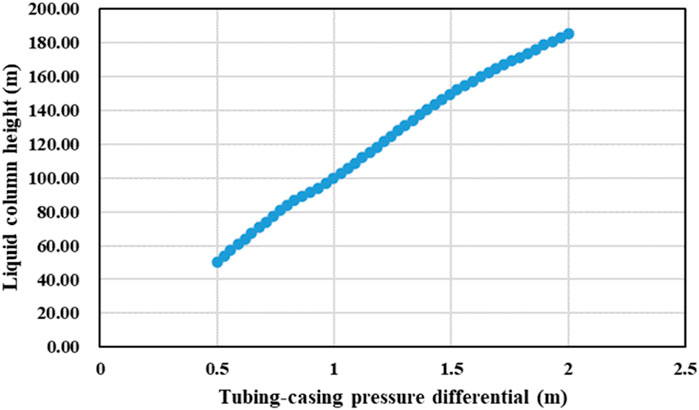
FIGURE 5. Relationship between tubing-casing pressure differential and the height of liquid column above the plunger.
The pressure relief is defined as the difference between the “tubing pressure in the gas well before opening” and the “stable production tubing pressure in the gas well after opening.” The magnitude of the pressure relief before and after opening reflects the pressure exerted by the gas to push the liquid column above the plunger and is indicative of the pressure recovery during the shut-in period. As a special form of intermittent gas lifting, plunger lift is essentially a high-frequency “intermittent production” as shown in Figure 6.
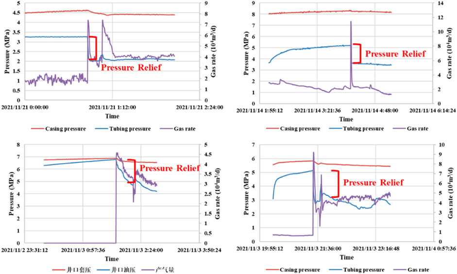
FIGURE 6. Pressure relief of gas wells.
3 Classification method of plunger lift well
For plunger lift wells, the change in tubing-casing pressure differential is an important evaluation indicator for the plunger lift. An important method to determine the effectiveness of plunger lift is to observe the height of the liquid column above the plunger. Classifying based on the liquid column height is not only simple and intuitive, but also has a certain corresponding relationship with the oil tubing-casing pressure differential as shown in Table 1. Generally, it is believed that in the case of sufficient gas volume, wells with a liquid column height >100 m have a better effect in reducing pressure by plunger lift for deliqufication. For wells with a liquid column height of 20–100 m, plunger lift can have a certain effect in reducing pressure for deliqufication. For wells with a liquid column height <20 m, plunger lift for deliqufication is ineffective.
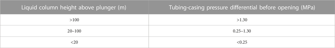
TABLE 1. Liquid column height corresponding to the tubing-casing pressure differential.
3.1 Numerical simulation of annular liquid level height in gas wells
Gas wells produced using plunger lift, during the opening phase, the liquid in the annular enters the tubing, and the high-pressure gas in the annular pushes the plunger upwards, so there is almost no liquid in the annular above the tubing shoe. During the closing phase, gas enters the casing first, and the casing pressure is restored more quickly. Due to the higher liquid column in the tubing compared to the annular, a small amount of liquid enters the annular space, but this can be ignored due to the much smaller cross-sectional area of the tubing compared to the annular. The simulation results of the OLGA software also confirmed that there is almost no liquid in the annular above the tubing shoe during a complete plunger cycle.
To study the variation of liquid level in the tubing-casing annulus during the plunger lift process, an OLGA numerical simulation model was developed based on the basic data from the Ning 209-H2 well, and the simulation of the annular holdup above the tubing shoe was conducted using the OLGA software as shown in Figure 7. This well is characterized by dry gas with a natural gas specific gravity of 0.65 and a production rate of 50,000 m3/d. The reservoir temperature is 107.2°C, with a pressure of 62.8 MPa. The reservoir depth is 3,988 m, the plunger depth is 3,200 m, and the simulation covers a 12-day production period.
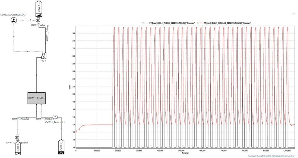
FIGURE 7. Profile of wellhead pressure difference in well Ning 209-H2.
The OLGA software was used to simulate the liquid holdup above the tubing shoe in the annulus (Figure 8). The results, indicate that there is almost no liquid present in the annular above the tubing shoe throughout a complete plunger cycle. This allows for the calculation of the liquid column height above the plunger.
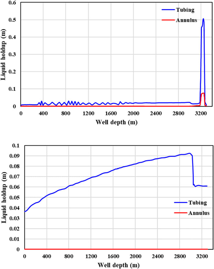
FIGURE 8. Simulation results of wellbore holdup by OLGA software.
3.2 Classification results for plunger lift gas wells
At the moment before opening a plunger lift well, the basic pressure relationships within the gas well are as follows: tubing pressure + gas column pressure in the tubing + liquid column pressure in the tubing = casing pressure + gas pressure in the casing. Since the heights of the gas and liquid columns in the tubing are unknown, iterative calculations can be performed through programming. An analysis was conducted on 8 field plunger lift gas wells, and the classification results are as presented in the Table 2.
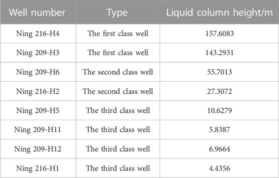
TABLE 2. Plunger lift well classification results.
4 Plunger lift well comprehensive evaluation method
4.1 Evaluation method of plunger lift
The evaluation of the effectiveness of plunger lift technology is mainly based on three aspects: the necessity of plunger lift, the operating conditions of plunger lift, and the deliquification effect of plunger lift technology. By considering the height of the liquid column above the plunger, the production effect under pressure, and the overall shut-in time, a comprehensive evaluation is made on whether a well is suitable for plunger lift technology (Figure 9).
(1) Necessity of plunger lift
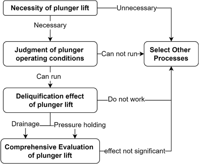
FIGURE 9. Evaluation flow of plunger lift.
The necessity of using plunger lift in a shale gas well is determined mainly by the critical gas rate profile. Considering that the field well type is horizontal well, in order to fully consider the influence of well inclination angle, and at the same time ensure the accuracy and practicability, the Wang Zhibin (W.Z.B.) empirical model is selected as the field gas well liquid carrying analysis model to analyze the gas well liquid carrying state and predict the production performance of the gas well.
W.Z.B. model:
where,
(2) Judgment of plunger operating conditions
The judgment of whether the self-conditions of a gas well can ensure the normal operation of plunger lift primarily relies on the reservoir pressure, gas-liquid ratio, and liquid accumulation height. The simulation results of the OLGA software for the failure pressure of gas well plunger lift under different gas-liquid ratios and liquid accumulation heights are shown in Figure 8. Generally, the smaller the gas-liquid ratio and the higher the liquid accumulation height, the more difficult it is to start the well, and the greater the failure pressure of the well. At the same time, at higher liquid accumulation heights, the gas-liquid ratio parameter has a relatively small impact on the well’s failure pressure as shown in Figure 10.
(3) Deliquification effect of plunger lift
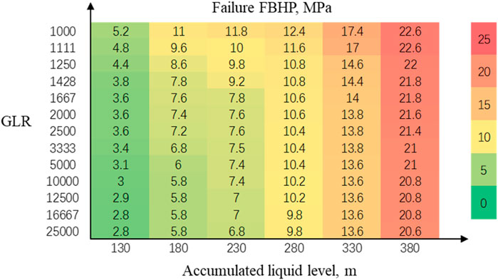
FIGURE 10. Failure pressure of plunger lift at different liquid accumulation heights.
The plunger lift can reduce slippage losses, improve lifting efficiency, and reduce the waste of gas energy. In a properly operating plunger lift well, during the shut-in phase, gas will preferentially enter the annular space, resulting in a faster recovery of casing pressure compared to tubing pressure. Then, during the opening phase, the high-pressure gas in the annulus drives the plunger and the liquid column upwards. The difference between the “tubing pressure in the gas well before opening” and the “stable production tubing pressure in the gas well after opening” is defined as the “the pressure relief ", which is used to determine whether the plunger lift technology serves to maintain pressure. The magnitude of the pressure relief before and after opening can reflect the pressure of the gas pushing the liquid column above the plunger (Table 3).
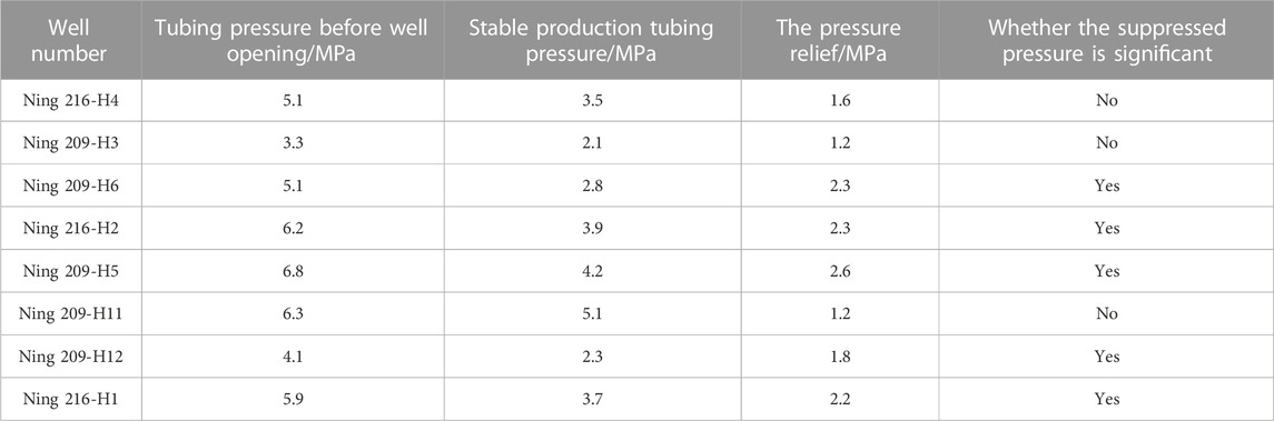
TABLE 3. Calculation results of pressure release difference for each well.
According to the simulation results of wellFlo software, the tubing-casing pressure differential can reflect the height of the liquid column in the wellbore. Therefore, the plunger lift can be run for one cycle, and the tubing-casing pressure differential before well opening can be used as the basis for judging the liquid column height above the plunger to determine whether the plunger lift plays the role of liquid drainage.
4.2 Effect evaluation of plunger lift well
Well Ning 216-H4 was selected to evaluate the plunger lift effect, and the evaluation results are as follows:
(1) Necessity of plunger lift
Well Ning 216-H4 is a horizontal well with a depth of 4051 m and an average gas production of 2.64 × 10⁴ m3/d. The critical gas rate calculated by the W.Z.B. model is 2.58 × 10⁴ m3/d, slightly lower than the production gas rate. The critical liquid accumulation depth is 2,372.48 m, with an on-site critical gas rate of 537.80 m3/d at the danger point as shown in Figure 11.
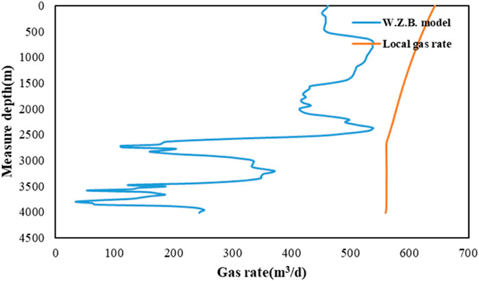
FIGURE 11. W.Z.B. model results.
In the 30 days before the plunger lift process was put into operation, the average drainage volume of the well was 24.13 m3/d, with daily drainage volumes ranging from 1 m3/d to 52 m3/d, showing significant fluctuations. Due to the rapid decline in reservoir energy and high water production, there were three instances of needing to resume production using gas lift in the month before the plunger was put into operation, hence the need for plunger lift production as shown in Figure 12.
(2) Judgment of plunger operating conditions

FIGURE 12. Production in the month before plunger lift.
After the implementation of plunger lift, the daily gas production of the well is 1.43 × 10⁴ m3, and the gas-liquid ratio is 1786, showing the characteristic of “large gas and large liquid”. The calculated liquid column height above the plunger reaches 154.0518 m, and the pressure at the end of the tubing is 6.31 MPa. Although the liquid column height is high, the energy of plunger lift is sufficient, and the plunger lift process can operate normally. One month after the plunger is put into operation, there is no need for gas lifting to resume production. Liquid column height calculation parameters are shown in Table 4.
(3) Deliquification effect of plunger lift
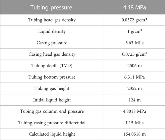
TABLE 4. Liquid column height calculation parameters.
Pressure relief can judge whether the plunger lift plays the role of holding pressure, reflecting the pressure size of the gas pushing the liquid column above the plunger. The tubing-casing pressure differential can reflect the height of the liquid column in the wellbore, and judge whether the plunger lift plays the role of deliquification.
①The role of well shut-in pressure holding and intermittent production.
The tubing pressure in Well Ning 216-H4 quickly dropped after opening, and then stabilized. After closing, it instantly recovered some pressure, and then slowly returned to stability. The casing pressure as a whole is basically stable. Before opening, the tubing pressure was 4.48 MPa, and after opening, the stable production tubing pressure was 2.87 MPa, with a pressure difference of 1.61 MPa (Figure 13). After the plunger is inserted, both the tubing pressure and the casing pressure have a certain recovery, with a pressure relief of 1.6 MPa, playing a certain role in backpressure, equivalent to high-frequency “intermittent production”.
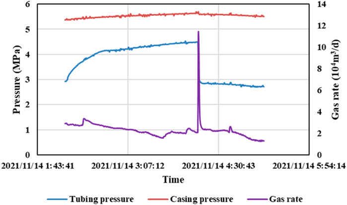
FIGURE 13. Plunger lift production process for gas well Ning 216-H4.
From a pressure perspective, both the tubing pressure and the casing pressure have shown some recovery, with a Pressure relief of 1.61 MPa before and after opening. One month after the plunger is put into operation, there is no need for gas lift to resume production, greatly saving production costs as shown in Figure 14.
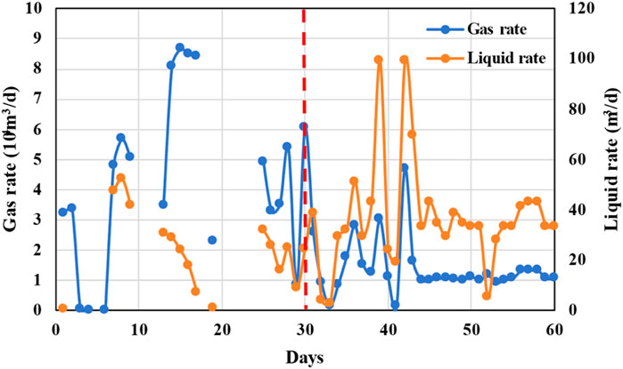
FIGURE 14. Comparison of production parameters before and after plunger lift.
In summary, the plunger lift has affected the production efficiency of the gas well, reducing production gas rate but increasing water production, reducing the need for gas lift to resume production, and significantly saving production costs.
5 Conclusion
(1) This paper analyzes the production characteristics of on-site gas wells and summarizes the key evaluation indicators of plunger lift, including casing pressure changes, production changes, liquid column plunger height, tubing-casing pressure differential changes, and differential size of pressure relief. Combined with numerical simulation methods, a complete set of methods for judging, classifying, and evaluating the effectiveness of plunger lift is proposed.
(2) According to the simulation results of the WellFlo software, the tubing-casing pressure differential can reflect the height of the liquid column in the wellbore, while the difference between the “opening tubing-casing pressure differential” and the “closing tubing-casing pressure differential” can reflect the changes in the liquid column height in the wellbore during opening and closing.
(3) The pressure relif is defined as the difference between the “tubing pressure in the gas well before opening” and the “stable production tubing pressure in the gas well after opening.” The magnitude of the pressure relif before and after opening can reflect the pressure of the gas driving the liquid column above the plunger and is an indication of pressure recovery during well shut-in.
(4) The holdup rate of the annulus above the tubing shoe was simulated using OLGA software, and it was found that there was almost no liquid present in the annular interface above the tubing shoe during the operation of the plunger lift process. This led to the calculation method for the liquid column height above the plunger: at the moment just before the plunger lift operation, “tubing oil pressure + gas column pressure inside the tubing + liquid column pressure inside the tubing = casing pressure + gas pressure inside the casing."
(5) An evaluation method for the effectiveness of the plunger lift was proposed, mainly based on the necessity of plunger lift, the judgment of plunger operating conditions and the deliquification effect of plunger lift. Taking well Ning 216-H4 as an example, a comprehensive assessment was made on whether the plunger lift process is suitable for the gas well based on the impact of factors such as the liquid column height above the plunger, shut-in pressure, and the duration of well shut-in.
Data availability statement
The original contributions presented in the study are included in the article/Supplementary Material, further inquiries can be directed to the corresponding author.
Author contributions
YF: Writing–original draft. JX: Writing–original draft. BL: Writing–original draft. JC: Writing–review and editing. MJ: Writing–review and editing. FY: Writing–review and editing.
Funding
The author(s) declare financial support was received for the research, authorship, and/or publication of this article. This work is financial support from National Natural Science Foundation of China (No. 52204059).
Conflict of interest
Authors YF, JX, BL, JC, MJ, and FY were employed by Engineering Technology Research Institute of PetroChina Southwest Oil and Gas Field Company.
Publisher’s note
All claims expressed in this article are solely those of the authors and do not necessarily represent those of their affiliated organizations, or those of the publisher, the editors and the reviewers. Any product that may be evaluated in this article, or claim that may be made by its manufacturer, is not guaranteed or endorsed by the publisher.
References
Bello, O. O., Falcone, G., Xu, J., and Scott, S. L. (2011). “Performance evaluation of a plunger-assisted intermittent gas lift system,” in Spe Production & Operations Symposium, Oklahoma City, Oklahoma, USA, March 27–29, 2011. doi:10.2118/141251-MS
Burns, M. (2018). Plunger-assisted gas lift and gas-assisted plunger lift in Paper presented at SPE Artificial Lift Conference and Exhibition - Americas, The Woodlands, Texas, USA, 28-30 August. SPE-190937-MS.
Chen, M., Sun, J., Gao, E., and Tian, H. (2021). A summary of wellbore fluid accumulation and drainage gas production technology in gas wells. IOP Conf. Ser. 621 (1), 012113. doi:10.1088/1755-1315/621/1/012113
Foss, D. L., and Gaul, R. B. (1965). Plunger-lift performance criteria with operating experience-venture avenue field. Drill. Prod. Pract. 1965, 124–140.
Han, Q. H. (2016). Automatic control plunger gas-lift drainage technology. Petrochem. Ind. Appl. 35 (12), 119–122. doi:10.3969/j.issn.1673-5285.2016.12.029
Hassouna, M. (2013). “Plunger lift applications: challenges and economics,” in Paper presented at the North Africa Technical Conference and Exhibition, Cairo, Egypt. SPE 164599.
Hingerl, F., Arnst, B., Cosby, D., Kreutzman, L., and Tyree, R. (2020). “The future of plunger lift control using artificial intelligence,” in SPE Artificial Lift Conference and Exhibition, Americas, Virtual.
HoseinMohammed, R. S. (2017). Evaluation and optimisation of oil wells on plunger lift in the main Soldado field offshore the Southwest Coast of Trinidad - a theoretical approach. Int. J. Petroleum Eng. 3 (1), 67. doi:10.1504/IJPE.2017.089000
Kaisare, N. S., Gupta, A., Kariwala, V., Nandola, N. N., Green, J. W., Seikel, G., et al. (2013). Control and optimization challenges in liquid-loaded shale gas wells. Ifac Proc. 46 (32), 227–232. doi:10.3182/20131218-3-IN-2045.00188
Kravits, M. S., Frear, R. M., and Bordwell, D. (2011). “Analysis of plunger lift applications in the Marcellus shale,” in Paper presented at the SPE Annual Technical Conference and Exhibition, Denver, Colorado, USA. SPE-147225-MS.
Lea, J., Rowlan, O. L., and Mccoy, J. N. (2007). “Measurement and calculation of key events during the plunger lift cycle,” in SPE Annual Technical Conference and Exhibition, Anaheim, California, U.S.A.
Lea, J. F. (1982). Dynamic analysis of plunger lift operations. J. Petroleum Techonology 34 (11), 2617–2629. doi:10.2118/10253-pa
Liu, H., Li, M., Liu, Q., and Zhang, L. (2020). Research and application of plunger gas lift technology in the fuling shale gas field. Pet. Drill. Tech. 48 (3), 102–107. doi:10.11911/syztjs.2020022
Maggard, J. B., Wattenbarger, R. A., and Scott, S. L. (2000). “Modeling plunger lift for water removal from tight gas wells,” in Paper presented at the SPE/CERI Gas Technology Symposium, Calgary, Alberta, Canada, April 2000, 2–5.
Meng, M., Ge, H., Shen, Y., Ji, W., and Li, Z. (2023b). Insight into water occurrence and pore size distribution by nuclear magnetic resonance in marine shale reservoirs, southern China. Energy & Fuels 37 (1), 319–327. doi:10.1021/acs.energyfuels.2c03395
Meng, M., Ge, H., Shen, Y., Ji, W., and Wang, Q. (2023a). Rock fabric of tight sandstone and its influence on irreducible water saturation in Eastern Ordos Basin. Energy & Fuels 37 (5), 3685–3696. doi:10.1021/acs.energyfuels.2c04011
Oyewole, P. (2016). “Artificial lift selection strategy to maximize unconventional oil and gas assets value,” in Spe North America Artificial Lift Conference & Exhibition, Texas, USA, October 2016. doi:10.2118/181233-MS
Oyewole, P. O., and Garg, D. O. (2007). “Plunger lift application and optimization in san juan north basin - our journey,” in Paper presented at the Production and Operations Symposium, Oklahoma City, Oklahoma, U.S.A.,, March 2007. doi:10.2118/106761-MS
Sask, D., Kola, D., and Tuftin, T. (2010). “Plunger lift optimization in horizontal gas wells: case studies and challenges,” in Paper presented at Canadian Unconventional Resources and International Petroleum Conference, Calgary, Alberta, Canada, 19-21 October. SPE-137860-MS.
Teymourifar, A., and Ozturk, G. (2018). A neural network-based hybrid method to generate feasible neighbors for flexible job shop scheduling problem. Univers. J. Appl. Math. 6 (1), 1–16. doi:10.13189/ujam.2018.060101
Wang, Q. R., Wang, J. X., Li, M. W., Yu, F., Cai, D. G., and Zeng, L. J. (2023). Plunger process in shale gas wells: influential factors and optimization methods. Nat. Gas Technol. Econ. 17 (03), 36–41. doi:10.3969/j.issn.2095-1132.2023.03.006
Xiong, S. Q., Zhang, B. B., Liu, P., Zhao, W., Li, Y. F., Zhang, J. B., et al. (2023). “Prediction and analysis of liquid carrying by plunger gas lift in wellbore,” in Paper presented at the ADIPEC, Abu Dhabi, UAE, October 2023.
Yang, Q. W., Zhou, S. D., Ma, L. W., Feng, W., lv, S. J., and He, Z. Z. (2022). Application and effect evaluation of plunger gas lift technology in shenmu gas field. Drill. Prod. Technol. 45 (1), 139–143. doi:10.3969/J.ISSN.1006-768X.2022.01.024
Zhao, Q. Q., Zhu, J. J., Cao, G. Q., Zhu, H. W., and Zhang, H. Q. (2021). Transient modeling of plunger lift for gas well deliquification. SPE J. 26, 2928–2947. doi:10.2118/205386-PA
Keywords: shale gas, plunger lift, applicability, indicators, evaluation method
Citation: Fan Y, Xiang J, Li B, Chen J, Jiang M and Yu F (2024) Applicability evaluation of plunger lift technology in shale gas wells. Front. Energy Res. 11:1343724. doi: 10.3389/fenrg.2023.1343724
Received: 24 November 2023; Accepted: 14 December 2023;
Published: 12 February 2024.
Edited by:
Hongyan Qu, China University of Petroleum, Beijing, ChinaReviewed by:
Zongxiao Ren, Xi’an Shiyou University, ChinaLeilei Zhang, Rice University, United States
Copyright © 2024 Fan, Xiang, Li, Chen, Jiang and Yu. This is an open-access article distributed under the terms of the Creative Commons Attribution License (CC BY). The use, distribution or reproduction in other forums is permitted, provided the original author(s) and the copyright owner(s) are credited and that the original publication in this journal is cited, in accordance with accepted academic practice. No use, distribution or reproduction is permitted which does not comply with these terms.
*Correspondence: Fan Yu, eXVfZmFuQHBldHJvY2hpbmEuY29tLmNu