- 1College of Safety Science and Engineering, Liaoning Technical University, Fuxin, China
- 2Key Laboratory of Mine Thermodynamic Disasters and Control of Ministry of Education, Liaoning Technical University, Huludao, China
- 3State Key Laboratory of Coal Mine Safety Technology, Shenyang Research Institute China Coal Technology & Engineering Group Corp, Shenyang, China
- 4Key Laboratory of Roads and Railway Engineering Safety Control, Ministry of Education, Shijiazhuang Tiedao University, Shijiazhuang, China
- 5Hebei Technology and Innovation Center on Safe and Efficient Mining of Metal Mine, Shijiazhuang, China
- 6Downhole Operation Company, CNPC Xibu Drilling Engineering Co., Ltd., Karamay, China
The intercalated layer of coal seam plays an important role in the propagation of hydraulic fracturing. To understand the role of the intercalated layer, a composite coal seam model considering the thickness of the intercalated layer was established. Based on the block distinct element method, the effects of rock structure (thickness of the coal seam and intercalated layer), rock properties (elastic modulus), and construction parameters (injection rate and fluid viscosity) on the penetration behavior of hydraulic fractures were analyzed. The results show that the intercalated layers influence the fracture deflection and have a hindering effect on fracture propagation. The thickness of the intercalated layer affects the stress on the bedding plane and the front edge of the fractures. On the contrary, the thickness of the coal seam mainly affects the penetration ability of hydraulic fractures and the extent of hydraulic fracture propagation. In addition, the elastic modulus of the intercalated layers and coal seams affects the hindering effect of the intercalated layer. The high injection rates reduce the hindering effect of the intercalated layer. When fracturing with a high-viscosity fluid, fractures are more likely to enter the intercalated layer. However, excessively high viscosity can make it difficult for fractures to penetrate the intercalated layer. This study can provide theoretical guidance for the fracturing of composite coal seams.
1 Introduction
Hydraulic fracturing is widely used to improve the permeability in low-permeability reservoirs. Based on numerical simulations (Huang et al., 2020; Liu et al., 2022; Huang et al., 2023a; Han et al., 2023) and experiments (Tan et al., 2019; Tan et al., 2020; Tan et al., 2023), there is a systematic understanding of the initiation and propagation mechanism of hydraulic fractures. The previous understanding of fracture propagation mainly focused on the homogeneous matrix. However, the real strata are heterogeneity and anisotropy since most reservoirs are hosted in sedimentary formations which have bedding planes or intercalated layers (Huang et al., 2019; Huang et al., 2023b). Hydraulic fractures show different behaviors when they encounter bedding planes or intercalated layers (Liu et al., 2022). Thus, the intercalated layer has an important influence on fracture propagation. This paper will address the propagation pattern of hydraulic fractures when they encounter the intercalated layers.
In recent years, the influence of the interface on hydraulic fracture propagation has gradually become a focus. Ju et al. (2018) analyzed the elastic modulus and Poisson’s ratio of adjacent rock layers for the propagation pattern of fractures that encounter the interface and discussed the role of contact properties of the interface. Huang et al. (2022) combined the effects of fracture toughness and elastic modulus from the perspective of energy dissipation to reduce and simplify the parameters of sensitivity analysis. Hadei and Veiskarami (2020) carried out a physical experiment based on manual models of adjacent rock layers. They discussed the effect of fracture energy of soft and hard rock layers and the effect of the angle of the adjacent layers. Guo et al. (2017) focused on the effect of stress differences and tensile strength of adjacent layers. Zhuang et al. (2023) carried out numerical simulations on the effects of initial stress field, stiffness difference, and interface angle with the phase field method. Qin et al. (2021) discussed the effect of stiffness ratio and strength ratio on the propagation behavior of fractures after they encounter the interface using the peridynamic method. Zhu et al. (2023) analyzed the effect of Young’s modulus, natural fractures, and plasticity on the penetration behavior of fractures through layers. Wang et al. (2021) presented a comprehensive summary of the key factors affecting fracture penetration behavior, including lithology, layer thickness, degree of natural fracture development, interface properties, and construction fracturing parameters. Zheng et al. (2019) analyzed the stress and deformation at the interface/bedding plane based on the block distinct element method and fracture mechanics theory. They think that the discontinuous deformation at the interface was the intrinsic cause of the height containment of the fracture. On this basis, the influence of construction parameters (Zheng et al., 2022) and interface properties (Bai et al., 2023) on fracture propagation was investigated separately. In summary, the importance of the propagation behavior of hydraulic fractures after encountering an interface is now well-recognized. The rock properties, interface characteristics, and construction parameters of the adjacent layers are the key parameters (Ji et al., 2015; Song et al., 2017; Song et al., 2020; Luo et al., 2022; Liu et al., 2023; Wu et al., 2023). However, the interface thickness between the intercalated layers was generally considered to be 0 in previous studies. In fact, the thickness of the interfaces also has an important influence on the fracture propagation considering some factors such as filling within the fracture. Therefore, a composite layered coal seam model considering the thickness of the intercalated layer was established based on the block distinct element method. Then, the influence of the elastic modulus and construction parameters on the penetration behavior of hydraulic fractures was studied.
This paper is organized as follows: first, a composite coal seam model considering the thickness of the intercalated layer was established. Then, the propagation pattern of hydraulic fractures was analyzed considering the thickness of the intercalated layer based on the established model. Next, the effect of the elastic modulus of the intercalated layer and coal seams on the penetration behavior of hydraulic fractures was analyzed. Finally, the effect of construction parameters including viscosity and injection rate on the penetration behavior of hydraulic fractures was analyzed. In our study, the propagation of hydraulic fracture in composite coal seams considering the thickness of the intercalated layer was systematically analyzed. It can provide theoretical guidance for fracturing in the composite coal seams.
2 Fracture propagation in the composite coal seams
2.1 Numerical model of composite coal seams
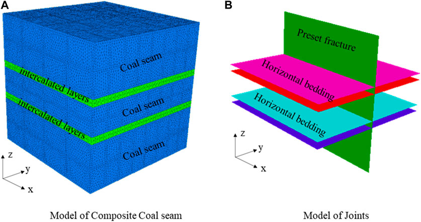
Considering the characteristics of the composite coal seam and the symmetry in numerical calculation, the numerical model containing the intercalated layer is established and shown in Figure 1A. It contains two intercalated layers and three coal seams. The size of the model is 6 m × 6 m × 6 m, where the thicknesses of the coal seam and the intercalated layer are set according to the experimental schemes. In the block distinct element method, the fracture needs to be preset. Therefore, a vertical preset joint was set along the center of the model. In addition, there was a horizontal bedding plane between the coal seam and the intercalated layer. As a result, this model contains four horizontal bedding planes and one vertical joint. The specific joint model is shown in Figure 1B. The injection point was set at the center of the model, and the flow boundary of the injection point was constant.
The composite coal seam consists of coal seams and intercalated layers. The combination of thicknesses affects the propagation of hydraulic fractures when encountering an intercalated layer, which in turn affects the fracture height (vertical characterization) and fracture length (horizontal characterization). In order to analyze the influence of the thickness of the intercalated layer and coal seam on the hydraulic fracture propagation, six schemes were designed, as shown in Table 1. When analyzing the influence of the thickness of the intercalated layer, the thickness of the coal seam is found to be 1 m. The thicknesses of the intercalated layers are 0.1–0.6 m in all six cases. When analyzing the influence of the thickness of the coal seam, the thickness of the intercalated layer is found to be 0.3 m, and the thicknesses of the coal seams are 0.6–1.1 m in a total of six cases.
Other parameters are set as follows: the injection rate is 0.001 m3/s. The viscosity of the fracturing fluid is 1 cp, and the fracturing time is 3,600 s. The cohesion of the joints is 2 MPa, the friction angle is 20°, and the tensile strength is 2 MPa. The Young’s modulus of the coal seam is 50 GPa, and that of the intercalated layer is 70 GPa. The Poisson’s ratio of both the coal seam and the intercalated layer is 0.25.
2.2 Effect of the intercalated layers on fracture propagation
2.2.1 The fracture propagation with different intercalated layers
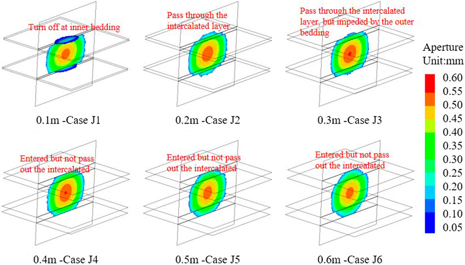
According to the scheme shown in Table 1, the fracture propagation of the intercalated layer with different thicknesses was calculated and is shown in Figure 2. According to the figure, when the thickness of the intercalated layer is 0.1 m, the hydraulic fracture fails to enter the intercalated layer after encountering the intercalated layer but turns to the bedding plane between the intercalated layer and the coal seam. When the intercalated layers are 0.2 and 0.3 m thick, the hydraulic fractures enter the bedding plane directly and penetrate out of the bedding plane. Although in both the cases the hydraulic fractures enter the intercalated layer, it should be noted that in some cases, the hydraulic fractures are impeded in penetrating the intercalated layer. As a result, the fracture length penetrating out the intercalated layer is less than the fracture length within the intercalated layer. In addition, the fracture height of the 0.3-m-thick interlayer was less than that of the 0.2-m-thick interlayer. When the thickness of the intercalated layer was 0.4 m or more, the hydraulic fractures enter the intercalated layer but fail to pass through it.
The intercalated layer affects the fracture propagation in the composite coal seam under the same fracturing conditions. In the formation with the thin intercalated layers, the fracture fails to enter the bedding plane and turns after encountering the bedding plane. As a result, the fracture height is less. Conversely, in the formation with the thick intercalated layer, the hydraulic fracture can enter the intercalated layer. Therefore, in the fracturing of composite coal seams containing thin intercalated layers, attention should be paid to the fracture deflection. The presence of thin intercalated layers results in insufficient fracture height. At this time, it is necessary to regulate the fracturing parameters to ensure that the hydraulic fracture can effectively penetrate the whole coal seam.
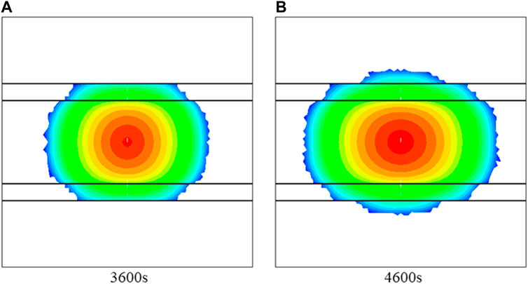
In addition, attention should be paid to the penetration behavior of hydraulic fractures. If the hydraulic fractures only enter but not pass through the intercalated layer, the hydraulic fractures still cannot connect the whole coal seam. In order to determine the obstruction of the intercalated layer to fracture penetration, the fracturing time of the J4 case is increased. As shown in Figure 3A, the fracture enters the intercalated layer but cannot pass through the intercalated layer. However, with the increase in fracturing time, the hydraulic fractures can break through the intercalated layer (Figure 3B). However, the propagation in the direction of its length (or horizontal direction) after fracture penetration is smaller than that of the center coal seam and intercalated layer. Therefore, the fracturing time should be prolonged appropriately for the hindering effect of the intercalated layer. At the same time, the discontinuity of fracture length due to the obstruction of the intercalated layer should be noted. If the existence of the intercalated layer is ignored, the fracturing efficiency may be lower than expected.
In summary, the influence of the intercalated layer on the fracture propagation includes the fracture deflection problem of encountering the thin intercalated layer and the hindering effect of the intercalated layer on fracture penetration. First, the hydraulic fracture turns after encountering the thin intercalated layer, and the height of the fracture is limited. In this case, it cannot effectively connect the whole coal seam. Second, the hindering effect of the intercalated layer prevents it from being passed through and subsequently affects the fracture height. The fractures penetrate the intercalated layer, but the fracture length was lower than that of the center coal seam.
2.2.2 The mechanisms of the intercalated layer thickness in propagation
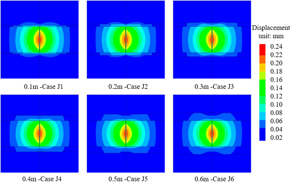
The hindering effect of the intercalated layer on fracture penetration is related to the discontinuous displacement on both sides of the intercalated layer (Zheng et al., 2019; Zhu et al., 2023). Therefore, to analyze the effect of the intercalated layer thickness, the displacement around the intercalated layer should be analyzed first. Figure 4 shows the displacement in the YOZ plane. It shows the displacements around the injection point caused by fracturing. The injection time is 1,600 s, when the hydraulic fracture is about to meet the inner bedding plane of the intercalated layer. It is an important indication for analyzing the behavior of the hydraulic fracture through the layer. As shown in the figure, the displacements are discontinuous on both sides of the intercalated layer. When the thickness is 0.1 m, the displacement discontinuity on the upper and lower sides of the intercalated layer is obvious. The discontinuity of the displacement on both sides of the intercalated layer decreases as the thickness is increased. Combined with the fracture morphology shown in Figure 2, it can be hypothesized that the fracture deflection is related to discontinuous displacements caused by the thin intercalated layer.
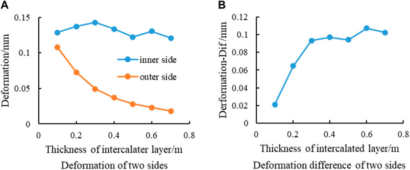
Figure 5 shows the deformation of the bedding planes on both the inner and outer sides of the intercalated layer. The deformation of the inner and outer sides of the intercalated layer is analyzed. As shown in Figure 5A, the difference in deformation on the inner side of the intercalated layer is small because the inner side is mainly affected by hydraulic fracture propagation. The displacement on the outer side of the intercalated layer decreases with decreasing thickness. The decrease rate is fast for the thin intercalated layer and slows down for a thick intercalated layer. Figure 5B analyzes the deformation difference between the inner and outer sides of the intercalated layer with different thicknesses. When the thickness of the intercalated layer is less than 0.3 m, the deformations of the two sides of the intercalated layer are sensitive to the thickness change. When the thickness of the intercalated layer is greater than 0.3 m, the difference in deformation is gradually stabilized.
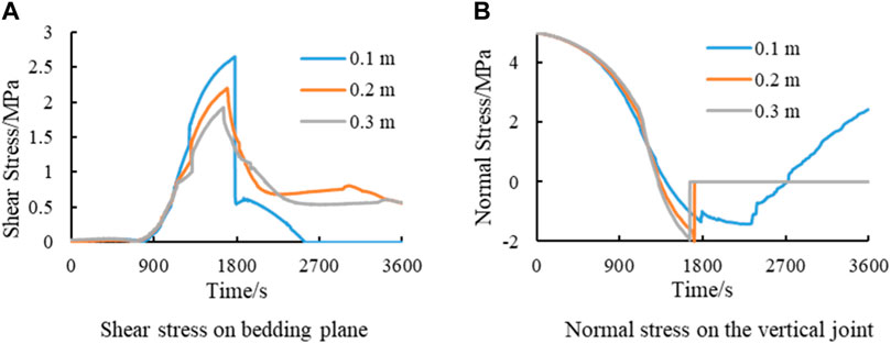
Combining the fracture propagation shown in Figure 2 and the deformation shown in Figure 5, it can be concluded that the effect of thin intercalated layers on the formation’s deformation and fracture propagation is more obvious. Therefore, the focus should be on the mechanical behavior of thin intercalated layers. In this paper, an intercalated layer with thickness less than 0.3 m is considered thin intercalated layer. Figure 6 analyzes the stress at the point where the hydraulic fracture intersects with the inner bedding plane of the intercalated layer. The shear stress on the horizontal bedding plane at the intersection is shown in Figure 6A. The shear stress characterizes the shear damage of the bedding plane. The shear damage of the bedding plane provides conditions for hydraulic fractures to expand toward the horizon. Figure 6B shows the normal stress on the vertical joint surface at the intersection. The normal stress characterizes the tensile failure of the vertical joint surface and can provide conditions for fractures to enter the intercalated layer. As shown in Figure 6A, the thickness of the intercalated layer affects the evolution of shear stresses on the bedding plane. The maximum shear stress can reach 2.36 MPa at the intercalated layer thickness of 0.1 m. The maximum magnitude of shear stress decreases as the thickness of the intercalated layer increases, and the maximum shear stress is 1.89 MPa when the thickness of the intercalated layer is 0.3 m. The deflection of hydraulic fractures is related to shear damage on the bedding plane. In other words, the fracture deflection is controlled by shear stress. Therefore, the higher the shear stress is, the higher the probability of deflection. The results show that the thinner the intercalated layer is, the faster the shear stress increases and the higher the maximum shear stress. It provides the reason for easy deflection in thin intercalated layers in terms of mechanical mechanisms. Figure 6B shows that the variation of normal stresses on the vertical joint surface is also affected by the thickness of the intercalated layer. The thickness of the intercalated layer affects the rate of reduction of normal stress. The greater the thickness of the intercalated layer is, the greater the reduction rate of normal stress. Therefore, for the thicknesses of 0.2 m and 0.3 m, the normal stress decreases to the tensile strength of the joint (normal stress is positive by compression), and the hydraulic fracture passes through the bedding plane and enters the intercalated layer. Then, the shear stress on the horizontal bedding plane gradually decreases and finally maintains a low value. So the fracture does not deflect.
It is possible to summarize the mechanical effect of the thickness of the intercalated layer on the penetration of the hydraulic fracture. For thin intercalated layers, the smaller the thickness, the faster the increase rate of shear stress on the horizontal bedding plane and the higher the maximum magnitude, and the slower the decrease rate of normal stress on the vertical joint surface, which is favorable for hydraulic fracture deflection. On the contrary, the larger the thickness, the slower the shear stress increase rate on the horizontal bedding plane and the lower the maximum value, and the more the normal stress reduction rate on the vertical joint surface, which is favorable for hydraulic fractures to pass through the bedding plane to enter the bedding plane.
2.3 The effect of coal seam thickness on fracture propagation
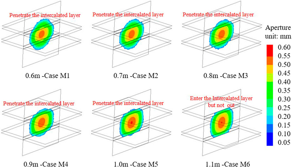
According to the experimental scheme shown in Table 1, the influence of coal seam thickness on fracture propagation is analyzed. The calculation results are shown in Figure 7. Since the thickness of the intercalated layer in this study is 0.3 m in all cases, the fractures are able to penetrate into the intercalated layer during the propagation. The effect of seam thickness on fracture propagation is the penetration behavior. The hydraulic fractures can penetrate the intercalated layer in all the cases with the thicknesses of 0.6–1.0 m of the coal seam. When the seam thickness was 1.1 m, the hydraulic fracture fails to penetrate the intercalated layer. In addition, hydraulic fractures can penetrate the intercalated layer in coal seams less than 1 m thick, but the degree of penetration varies. In conclusion, the thinner the coal seam, the smaller the hindering effect. As the coal seam thickens, the range of penetration of hydraulic fractures is smaller.
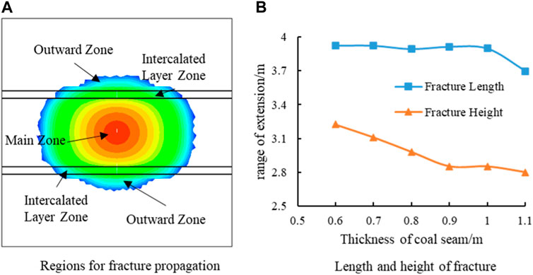
The thickness of the coal seam affects the penetration ability. Then, it affects the extent range of hydraulic fracture propagation. Figure 8A categorizes hydraulic fractures into the main zone, intercalated layer zone, and outward zone according to their location. The thickness of the coal seam directly determines the height of the main fracture zone. Figure 8B summarizes the fracture propagation length and height for different coal seam thicknesses. The results show that the length of hydraulic fractures remains generally consistent, but the height of hydraulic fractures is affected by the thickness of the coal seam. Hydraulic fracture height decreases gradually with the increase in the coal seam thickness. Low fracture height implies a reduction in the extent of fracturing.
In summary, the thickness of the coal seam mainly affects the ability of the hydraulic fracture to pass through the intercalated layer and the range of hydraulic fracture propagation. As the thickness of the seam increases in a composite seam, the hindering effect of the intercalated layer on the height of the fractures should be considered. When the coal seam is thin, the influence of the intercalated layer on the propagation of fractures is less. While the coal seam is thick, the influence of the intercalated layer on the vertical propagation of fractures is more, which should be emphasized in the design of fracturing.
3 Effect of elastic modulus on fracture propagation
3.1 The fracture propagation with different elastic moduli
The elastic modulus characterizes the deformability of rocks. Furthermore, the difference in the elastic modulus between the intercalated layer and coal seams has a significant effect on the penetration behavior of fractures. In order to analyze the effect of the elastic modulus on fracture propagation, the elastic moduli of the coal seam (Ec) are taken to be 20 GPa, 30 GPa, 40 GPa, and 50 GPa, and the moduli of the intercalated layer (Ei) are taken to be 40 GPa, 50 GPa, 60 GPa, and 70 GPa. Combined simulations are carried out for various scenarios, and a total of 16 sets of simulation scenarios are designed. The fracture propagation under each case is summarized in Figure 9.
First, the effect of the Ec is analyzed. Moreover, the same row shown in Figure 9 has the same Ei, and the Ec varies. With a small Ec, hydraulic fractures can penetrate the intercalated layer. As the Ec increases, the hindering effect of the intercalated layer on the vertical propagation of the fractures is enhanced. Second, the effect of Ei is analyzed. The same column in the figure has the same Ec and different Ei. The effect of Ei on hydraulic fracture propagation has different patterns at high and low Ec. In the low Ec (left first column), the Ei has little effect on fracture propagation. In the high Ec (50 GPa), hydraulic fractures can penetrate the intercalated layer when the Ei is low (40 GPa and 50 GPa). When the Ei is high (60 GPa and 70 GPa), the hydraulic fractures turn after encountering the intercalated layer, and the intercalated layer hinders the vertical propagation of the hydraulic fractures.
In summary, the influence of Ec on fracture propagation can be summarized. The hindering effect of the intercalated layer on fracture propagation increases with the increase in Ec. Furthermore, the influence of the Ei on the behavior of fracture propagation can be summarized. In low elastic modulus coal seams, the influence of the Ei on fracture propagation is small. Conversely, in high elastic modulus coal seams, the hindering effect of the intercalated layer on hydraulic fractures increases with the increase in the Ei.
3.2 The effect of the elastic modulus of coal seams
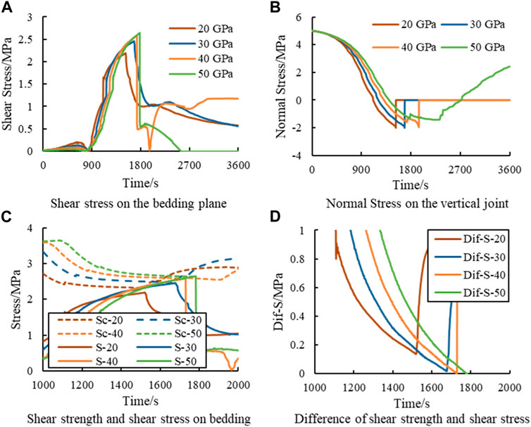
According to Figure 9, as the Ec increases, it becomes more difficult for hydraulic fractures to pass through the intercalated layer. The elastic modulus characterizes the deformation. As shown in the figure, the hydraulic fracture with a small elastic modulus has a large aperture. Moreover, the aperture decreases with the increase in the Ec. The aperture determines the fracture volume. Furthermore, different fracture volumes under the same fluid injection volume determine the difference of pressure within the fracture. Different pressures ultimately cause differences in stress evolution. Figure 10 analyzes the stress evolution at the intersection of the hydraulic fracture and the intercalated layer for different Ec when the Ei is 70 GPa. The figure shows that the Ec affects the distribution of shear stresses on the bedding plane and normal stresses on the vertical joint.
First, the elastic modulus affects the change gradient in stress. As shown in Figures 10A, B, the stress curve for the coal seam with an elastic modulus of 20 GPa is on the leftmost side, which means that the stress change corresponding to this elastic modulus is earlier than that in the other cases. Whereas the stress evolution is related to fracture propagation, as the fracture approaches a certain point (numerical node), the stress profile at that point changes significantly. In addition, the sequence of stress curve changes in the figure characterizes the rate of hydraulic fracture propagation. Therefore, it can be known that hydraulic fractures expand fast when the Ec is small and expand slow when the Ec is large.
As shown in Figure 10A, the maximum shear stress increases with the increase in the Ec. Shear stress causes shear damage of the bedding plane. The shear stress increases with Ec, which subsequently increases the tendency of hydraulic fractures to turn toward the bedding plane and increases the hindering effect of the intercalated layer. However, it is worth noting that as shown in Figure 10A, the shear stress increases fastest at low Ec (the slope of the curve is the largest), but its maximum shear stress is at the lowest Ec. The paradox of a fast increase in the shear stress but a low maximum value needs to be explained in terms of the change in normal stress. From Figure 10B, it can be seen that the normal stress on the vertical joint surface decreases with injection time. The fastest rate of stress reduction occurs when the Ec is 20 GPa. When the stress decreases to −2 MPa, reaching the tensile strength of the joint, the hydraulic fracture expands vertically through the bedding plane. Now, the shear stress on the horizontal bedding plane reaches its peak. Due to the rapid decrease in normal stress, the shear stress does not increase. As the Ec increases, fracture propagation slows down, thus requiring more time for normal stress to decrease to tensile strength. Finally, the maximum shear stress increases. When the Ec is 50 GPa, the normal stress does not reduce to the tensile strength, and the shear stress reaches the shear strength of the bedding plane. Now, the bedding plane shear damage occurs, and the hydraulic fractures turn to the bedding plane.
Figure 10C shows the corresponding shear strength and shear stress curves of the bedding plane at different Ec. In the figure, the Sc curve represents shear strength, and the S curve represents shear stress. The shear strength (Sc) of the bedding plane gradually decreases with injection, while the shear stress (S) gradually increases. Finally, the two are gradually close to each other. Figure 10D shows the difference between the shear strength and shear stress (Dif-S) curves. According to the figure, Dif-S is gradually decreasing before the damage occurs at the intersection point. The minimum value of Dif-S decreases with the increase in the Ec. Actually, this difference can reflect the tendency of the shear damage of the bedding plane.
In summary, the mechanism of the Ec on the hindering effect of the intercalated layer is as follows: the influence of the elastic modulus on the deformation determines the fracture propagation rate and the stress distribution characteristics. The fracture propagates fast under low elastic modulus. So the normal stress on the vertical joint decreases fast. Then, the fracture is preferred to extend vertically through the intercalated layer. Under high elastic modulus, the fracture propagates slowly. So the normal stress on the vertical joint decreases slowly. Then, the shear stress on the bedding plane is preferred to reach the shear strength, and the bedding plane undergoes shear damage. The minimum value of Dif-S can be used to characterize the hindering effect of the intercalated layer. The smaller the Dif-S, the stronger the hindering effect. Therefore, with the increase in the elastic modulus, the minimum Dif-S decreases and the hindering effect of the bedding plane increases.
3.3 The effect of the elastic modulus of the intercalated layer
From Figure 9, it can be seen that the effect of Ei on the hydraulic fracture propagation pattern needs to consider the Ec. When the Ec is small (such as 20 GPa), changes in Ei have little effect on hydraulic fracture penetration. When the Ec is large (such as 50 GPa), the effect of Ei on hydraulic fracture penetration is significant. As shown in the figure, the fracture pattern changes from passing through the intercalated layer to being hindered by the intercalated layer with increase in Ei. Therefore, the effect of the intercalated layer on fracture patterns should be discussed for the classification of different Ec values.
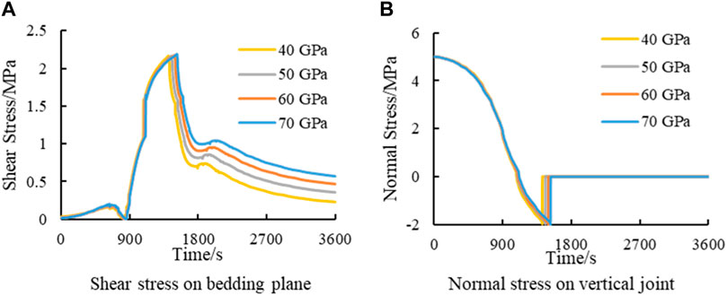
Figure 11 shows the stress evolution curve corresponding to the Ec of 20 GPa. Since the coal seams have the same elastic modulus, the curves overlap before encountering the intercalated layer. As the fracture approaches the intercalated layer, the stress curves begin to differ. At this stage, the stress curve corresponding to 40 GPa is more to the left, indicating that stress changes occur earlier. The curve corresponding to 70 GPa is most to the right, indicating that stress changes occur later. Therefore, the effect of Ei on the stress change is mainly manifested in the following ways. The lower the Ei is, the earlier and faster the stress response at the fracture approaching. Although the effect of Ei on the stress evolution has been analyzed above, the overall influence of the interacted layer on the maximum shear stress and the minimum normal stress is very small. The stress curves shows that the normal stress reaches the tensile strength of the vertical joint and the hydraulic fracture directly penetrates the intercalated layer. Furthermore, the shear stress has not reached the shear strength at this point, so hydraulic fractures do not turn. In seams with low elastic modulus, Ei has little effect on the penetration behavior of hydraulic fractures.
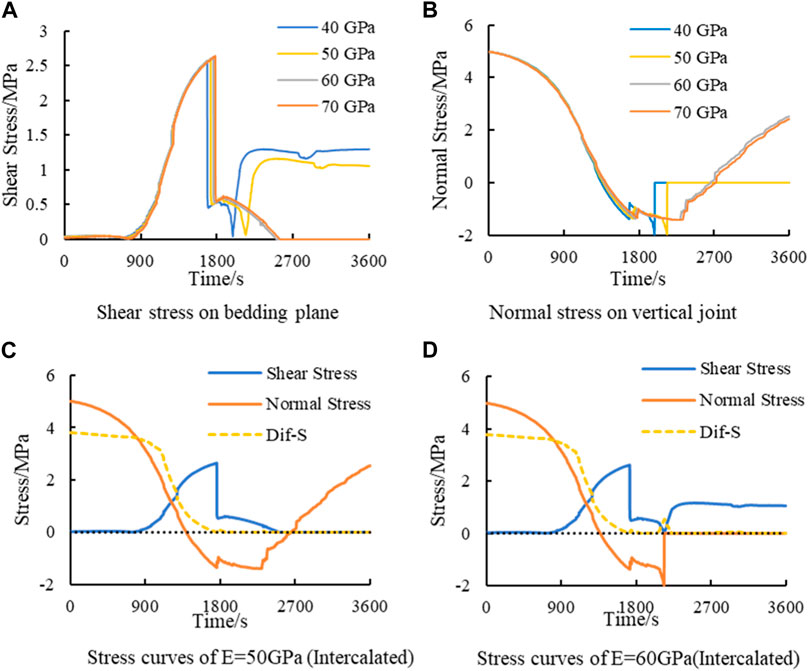
Figure 12 shows the stress variation curves for the elastic modulus of 50 GPa. Combining the analysis in Figures 12A, B, the normal stress is shown to decrease to reach the tensile strength and the hydraulic fracture penetrates the intercalated layer at the Ei of 40 GPa and 50 GPa. The normal stresses do not reach the tensile strength at the Ei of 60 GPa and 70 GPa, so the hydraulic fractures fail to penetrate the intercalated layer.
All the shear stress curves shown in Figure 12A undergo a sudden vertical decrease. Combining the results of Zheng et al. (2022) and Figure 10, it can be seen that the vertical decrease in the shear stresses indicates that shear damage has occurred at this time. Although shear damage occurs in all horizontal bedding planes, the propagation patterns of hydraulic fractures at different Ei are different. In order to analyze the effect of Ei, the two cases of Ei of 50 GPa and 60 GPa are taken as examples to analyze the stress evolution. Their stress curves are plotted in Figures 12C, D. From Figure 12C, it can be seen that when the Ei is 50 GPa, the horizontal bedding plane can still withstand a certain amount of shear stress after shear failure. Thus, stresses and strains can be transferred from one side to the other side of the bedding plane. Therefore, the normal stresses on the vertical joint surface can continue to decrease. Finally, the normal stress is reduced to the tensile strength of the vertical joint, and the hydraulic fractures extend vertically through the bedding plane. When the Ei is 60 GPa, the stress and strain transfer between the two sides of the bedding plane is poor after the shear damage. So the normal stress does not reduce. As a result, the hydraulic fracture cannot pass through the bedding plane. Then, the hydraulic fracture can only continue to be extended along the bedding plane. Eventually, the fracture at this point opens up and loses its shear capacity, and both sides of the bedding plane lose the transfer ability of stress and strain. In summary, the mechanism of the intercalated layer on the penetration behavior in the high elastic modulus coal seam is as follows: Ei affects the reduction of the normal stress on the vertical joint. When Ei is lower, the normal stress can continue to decrease and the hydraulic fractures can penetrate the bedding plane. When Ei is higher, the normal stress cannot continue to decrease, and then hydraulic fractures cannot pass through the bedding plane.
4 The effect of construction parameters on fracture propagation
The above has clarified the influence of rock structure (thickness) and rock properties (elastic modulus) on hydraulic fracture propagation. However, the rock structure and rock properties belong to the inherent properties of the stratum, and they are difficult to be changed artificially. During the fracturing operation, the fracturing parameters, including injection rate and fluid viscosity, can be controlled to manually intervene on the fracture penetration behavior. Therefore, revealing the influence of construction parameters on fracture propagation in composite coal seam fracturing has an important role for fracturing construction. Based on this, the influence of the injection rate and fluid viscosity on fracture propagation is calculated and revealed.
4.1 The influence of the injection rate on fracture propagation
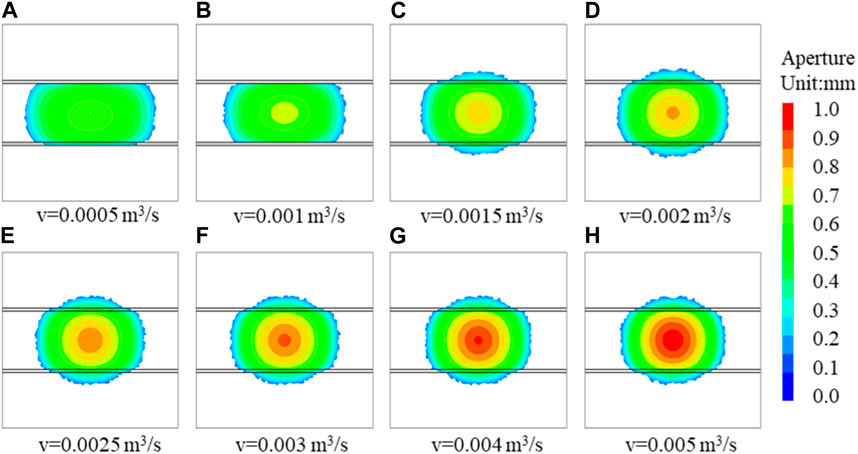
The injection rate is one of the key construction parameters that can be artificially controlled in fracturing construction. In order to analyze the effect of injection rate on fracture propagation, eight injection schemes are developed as shown in Figure 13. The viscosity in the scheme is 1 cp. In order to unify the evaluation criteria, the total injection volume is used as the evaluation criterion in the simulation. Figure 13 shows the fracture propagation under the same injection volume. It can be seen from the figure that when the injection rate is 0.0005 m3/s (500 mL/s) and 0.001 m3/s (1000 mL/s), the hydraulic fracture is hindered after encountering the bedding plane, and the hydraulic fracture fails to pass through the intercalated layer. When the injection rate is 0.0015 m3/s, the hydraulic fracture passes through the intercalated layer. However, the hydraulic fractures on both sides of the intercalated layer are discontinuous. The intercalated layer has a strong hindering effect on the hydraulic fracture. With the increase in the injection rate, the hindering effect of the intercalated layer on the hydraulic fracture is reduced. Therefore, in the fracturing design, the injection rate should be designed according to the penetration behavior of the fracture, combined with the rock structure and rock property. The high injection rate is more conducive to the hydraulic fracture through the intercalated layer to ensure the fracture height. However, the high injection rate requires stronger power equipment, high injection pressure, and increased cost. Although the high injection rate is helpful for the fracture to penetrate the layer, the injection rate should be determined according to the actual situation of the reservoir.
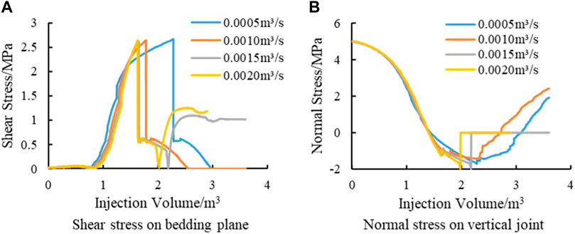
Figure 14 shows the shear stress on the horizontal bedding plane and the normal stress on the vertical joint plane corresponding to the case shown in Figures 13A–D. Due to the different injection rates, the corresponding injection time is different at the same injection volume. In order to unify the evaluation criteria, the total injection volume is plotted along the x-axis in the figure. As shown in the figure, when the injection rate is low, the shear stress on the horizontal bedding increases slowly. With the increase in the injection rate, the shear stress rise rate increases (the curve moves to the left). When the injection rate is bigger than 0.0015 m3/s, the shear stress curve basically coincides. It can be seen from Figure 14A that the shear stress curves all show a vertical decline, which indicates that shear failure occurs on the horizontal bedding plane. It can be seen from Figure 14B that the normal stress of 0.0015 and 0.0020 m3/s can continue to decline after the shear failure of the horizontal bedding plane. As the normal stress decreases to the tensile strength, the vertical joint opens and the hydraulic fracture passes through the bedding plane. When the injection rate is low, the normal stress cannot continue to decrease, and the fractures can only expand along the bedding plane.
In summary, the influence of the injection rate on the penetration of hydraulic fractures is as follows. At a small injection rate, the normal stress on the vertical joint cannot reach its tensile strength, and the hydraulic fracture cannot expand vertically. Therefore, the hydraulic fractures tend to expand along the horizontal bedding plane. With the increase in the injection rate, the normal stress on the vertical joint can reach the tensile strength, and the hydraulic fracture can extend along the vertical direction, weakening the trend of extending along the horizontal bedding plane. As a result, the hindering effect of the intercalated layer fractures decreases, and hydraulic fractures tend to expand directly through the intercalated layer.
4.2 Effect of fluid viscosity on fracture propagation
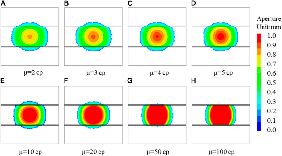
The fluid viscosity is another key construction parameter that can be artificially controlled in fracturing construction. In order to analyze the influence of fluid viscosity on fracture propagation, eight viscosity schemes are designed as shown in Figure 15. In the scheme, the fixed injection rate is 0.001 m3/s. Figure 15 shows the fracture morphology under different viscosities.
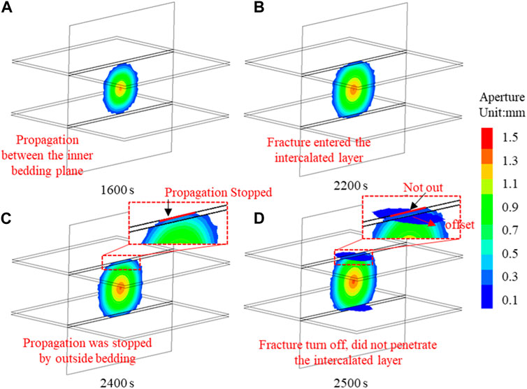
As shown in the figure, the hydraulic fracture is hindered by the bedding plane with the viscosities of 50 cp and 100 cp. It means that the hindering effect of the intercalated layer on hydraulic fractures increases with the increase in fluid viscosity. This conclusion is inconsistent with the previous understanding of the influence of construction parameters on the penetration behavior (Zheng et al., 2022). In the previous studies, the research on the penetration behavior of the hydraulic fracture was mainly aimed at the weak plane of bedding, while we establish the actual intercalated layer considering the thickness. Different from the above simulation, the hydraulic fracture penetrated the internal bedding plane and entered the intercalated layer but failed to penetrate the external bedding plane. In order to analyze this process, the hydraulic fracture propagation process with the injection viscosity of 100 cp is given in Figure 16. Before 1,600 s, the hydraulic fracture expands in the main zone, and the hydraulic fracture is penny-shaped. At 1,600 s, the hydraulic fracture reaches the inner bedding plane of the intercalated layer. Subsequently, hydraulic fractures can pass through the bedding plane into the intercalated layer (Figure 16B), which is consistent with the previous understanding of the influence of construction parameters on the fracture penetration behavior. However, this paper considers the thickness of the actual intercalated layer, so the intercalated layer is divided into two layers. Hydraulic fractures can enter the intercalated layer, but they are hindered by the outer bedding plane coming out of the intercalated layer (Figure 16C). Subsequently, the internal bedding plane reached the shear failure condition, and the hydraulic fracture turned to expand along the internal bedding plane (Figure 16D). The propagation process of fractures under high fluid viscosity is as follows: first, the hydraulic fractures pass through the bedding plane and enter the intercalated layer. Then, the hydraulic fractures are hindered when they pass through the intercalated layer. Finally, the hydraulic fractures turn to expand along the internal bedding plane. In this process, although the hydraulic fracture expands along the internal bedding plane, the fracture first passes through the bedding plane, but it turns to the bedding plane due to obstruction. This is different from the direct offset of hydraulic fractures after encountering bedding planes in the previous studies.
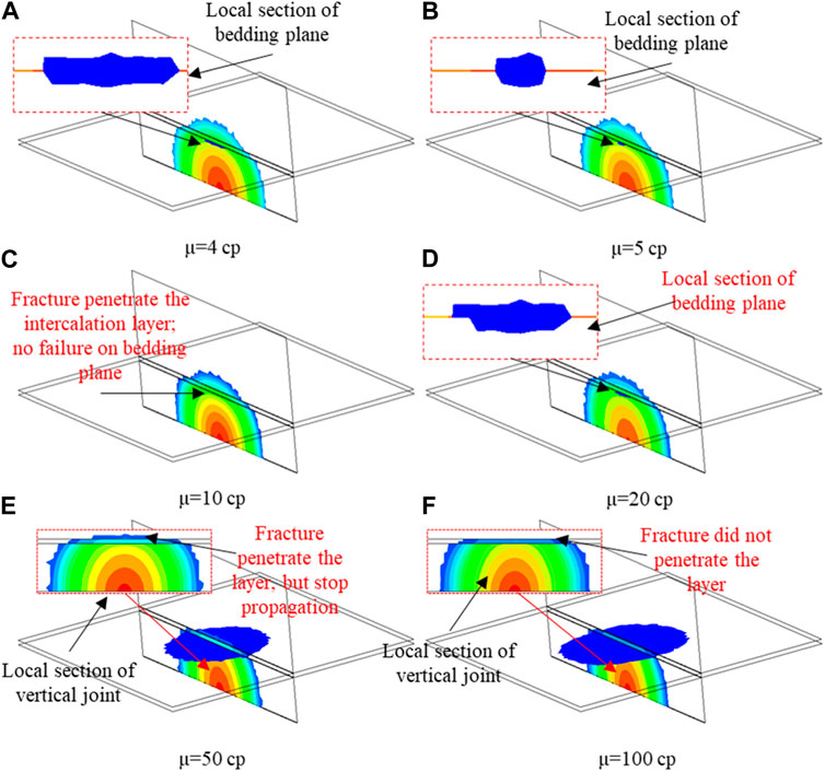
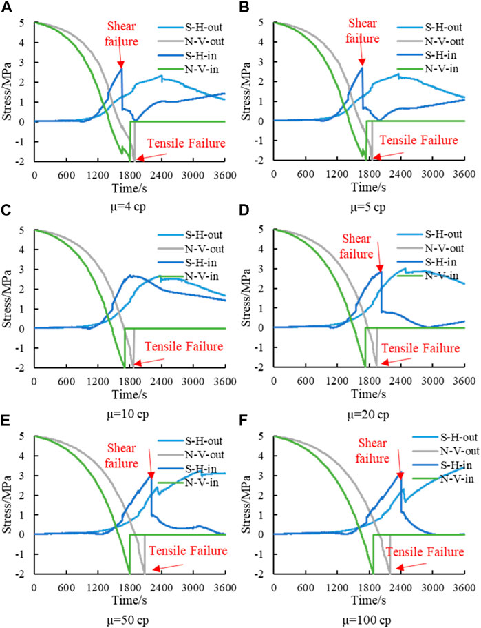
In summary, when considering the two bedding planes and the thickness of the intercalated layer, the viscosity of the fracturing fluid has a significant effect on the penetration of the hydraulic fracture through the intercalated layer. Figure 17 shows the details of fracture propagation under different viscosities for the analysis of the propagation characteristics of hydraulic fractures under different viscosities. For clarity, only the top half of the fractures is shown. As shown in the figure, although the hydraulic fracture passes through the intercalated layer, the shear failure occurs on the internal bedding plane when the viscosity is 4 cp and 5 cp. The shear failure range at low viscosity is greater than that at high viscosity. Furthermore, the shear range characterizes the hindrance of the bedding plane. The larger the shear failure range is, the greater the hindrance effect. It means that in this viscosity range, the hindering effect of the bedding plane decreases as the viscosity increases. When the viscosity is 10 cp, the hydraulic fracture passes through the intercalated layer, and no shear failure occurs on the bedding plane. When the viscosity is 20 cp, the hydraulic fracture passes through the intercalated layer, but the shear failure area appears on the horizontal bedding plane. When the viscosity is 50 cp, the hydraulic fracture can pass through the intercalated layer, but it fails to expand vertically after passing out. In addition, the hydraulic fracture expands along the horizontal bedding plane.
Figure 18 shows the stress evolution curve corresponding to Figure 17. In order to facilitate the marking, the shear stress on the horizontal bedding plane is represented by S-H, and the normal stress on the vertical joint plane is represented by N-V. The position of the intersection point between the internal bedding plane and the vertical joint plane is denoted by in. The position of the intersection point between the outer bedding plane and the vertical joint is denoted by out. As shown in the figure, when the viscosity is 4 cp and 5 cp, the horizontal bedding plane first undergoes shear failure. Then, the N-V can continue to decrease to the tensile strength, so the hydraulic fracture eventually expands vertically. When the viscosity is 10 cp, no shear failure occurs on the horizontal bedding plane. As the viscosity continues to increase, under the conditions of 20 cp, 50 cp, and 100 cp, the vertical joint first undergoes tensile failure. Then, the internal bedding surface undergoes shear failure. Therefore, the viscosity of the fracturing fluid affects the order of failure of the horizontal bedding plane. Under the condition of low viscosity, the shear failure of the horizontal bedding plane precedes the tensile failure of the vertical joint. In a word, the viscosity affects whether the hydraulic fracture can penetrate the intercalated layer by the shear failure of the horizontal bedding plane. At this time, the greater the viscosity, the easier it is for hydraulic fractures to enter the intercalated layer.
In summary, this study considers the thickness of the intercalated layer. High viscosity increases the tendency for fractures to enter the intercalated layer. Furthermore, the difficulty of passing out through the intercalated layer increases. This understanding is different from the existing understanding of the impact of construction parameters on the penetration behaviors. During fracturing operations, it is not advisable to blindly increase the viscosity of fracturing fluids, but rather to consider the increased difficulty of penetrating the interlayer caused by increased viscosity of fracturing fluids.
5 Conclusion
In this paper, a composite coal seam model considering the thickness of the intercalated layer is established. Based on the block distinct element method, the effect of rock structure (thickness of coal seam and intercalated layer), rock properties (elastic modulus), and construction parameters (injection rate and fluid viscosity) on the penetration behavior of hydraulic fractures is analyzed. The main conclusions are as follows:
(1) The influence of the intercalated layer on the fracture propagation of the composite coal seam includes the fracture deflection problem of the thin intercalated layer and the hindering effect of the intercalated layer on fracture penetration.
(2) The thin intercalation layer leads to a rapid increase in shear stress on the horizontal bedding plane, weakening the decrease in normal stress on the vertical joint plane. Therefore, the thin intercalation layer is beneficial for the offset of hydraulic fracture. Conversely, the thick intercalation layer is beneficial for the hydraulic fracture to penetrate through the bedding plane into the intercalation.
(3) The thickness of the coal seam mainly affects the ability of the hydraulic fracture to penetrate the intercalated layer and the propagation range. When the coal seam is thin, the intercalated layer has little effect on the propagation of the fracture. When the coal seam is thick, the intercalated layer has a substantial influence on the vertical propagation range.
(4) The hindering effect of the intercalated layer on the fracture increases with the increase in the elastic modulus of the coal seam. In the low elastic modulus coal seam, the intercalated elastic modulus has little effect on the fracture propagation. In the coal seam with high elastic modulus, the hindering effect of the intercalated layer on the hydraulic fracture increases with the increase in the elastic modulus of the intercalated layer.
(5) With the increase in the injection rate, the hindering effect of the intercalated layer on fractures decreases, and hydraulic fractures tend to penetrate the intercalated layer. With the increase in fluid viscosity, the trend of hydraulic fractures entering the intercalated layer increases, but the difficulty of penetrating the intercalated layer also increases.
Data availability statement
The original contributions presented in the study are included in the article/Supplementary Material; further inquiries can be directed to the corresponding authors.
Author contributions
HG: writing–original draft and writing–review and editing. BJ: supervision and writing–review and editing. YL: funding acquisition, investigation, and writing–review and editing. YZ: conceptualization, funding acquisition, methodology, software, and writing–original draft. BS: writing–review and editing. HW: writing–review and editing. TZ: writing–review and editing. WW: writing–review and editing, funding acquisition, and supervision. QN: formal analysis, validation, and writing–review and editing.
Funding
The authors declare financial support was received for the research, authorship, and/or publication of this article. The authors acknowledge the support provided by the Natural Science Foundation of Hebei Province (E2021210036 and E2021210128).
Conflict of interest
Authors HG and YL were employed by Shenyang Research Institute China Coal Technology & Engineering Group Corp. Author BS was employed by Downhole Operation Company, CNPC Xibu Drilling Engineering Co., Ltd.
The remaining authors declare that the research was conducted in the absence of any commercial or financial relationships that could be construed as a potential conflict of interest.
Publisher’s note
All claims expressed in this article are solely those of the authors and do not necessarily represent those of their affiliated organizations, or those of the publisher, the editors, and the reviewers. Any product that may be evaluated in this article, or claim that may be made by its manufacturer, is not guaranteed or endorsed by the publisher.
References
Bai, Y., Hu, Y., Liao, X., Tan, J., Zheng, Y., and Wang, W (2023). Research on the influence of stress on the penetration behavior of hydraulic fracture: perspective from failure type of beddings. Front. Earth Sci. 11, 11. doi:10.3389/feart.2023.1163295
Guo, J., Luo, B., Lu, C., Lai, J., and Ren, J (2017). Numerical investigation of hydraulic fracture propagation in a layered reservoir using the cohesive zone method. Eng. Fract. Mech. 186, 195–207. doi:10.1016/j.engfracmech.2017.10.013
Hadei, M. R., and Veiskarami, A. (2020). An experimental investigation of hydraulic fracturing of stratified rocks. Bull. Eng. Geol. Environ. 80 (1), 491–506. doi:10.1007/s10064-020-01938-0
Han, L., Xizhe, L., Liu, Z., Duan, G., Wan, Y., Guo, X., et al. (2023). Influencing factors and prevention measures of casing deformation in deep shale gas wells in Luzhou block, southern Sichuan Basin, SW China. Petroleum Explor. Dev. 50 (4), 979–988. doi:10.1016/s1876-3804(23)60443-4
Huang, L., Dontsov, E., Fu, H., Lei, Y., Weng, D., and Zhang, F (2022). Hydraulic fracture height growth in layered rocks: perspective from DEM simulation of different propagation regimes. Int. J. Solids Struct. 238, 111395. doi:10.1016/j.ijsolstr.2021.111395
Huang, L., He, R., Yang, Z., Tan, P., Chen, W., Li, X., et al. (2023a). Exploring hydraulic fracture behavior in glutenite formation with strong heterogeneity and variable lithology based on DEM simulation. Eng. Fract. Mech. 278, 109020. doi:10.1016/j.engfracmech.2022.109020
Huang, L., Liu, J., Zhang, F., Dontsov, E., and Damjanac, B (2019). Exploring the influence of rock inherent heterogeneity and grain size on hydraulic fracturing using discrete element modeling. Int. J. Solids Struct. 176-177, 207–220. doi:10.1016/j.ijsolstr.2019.06.018
Huang, L., Liu, J., Zhang, F., Fu, H., Zhu, H., and Damjanac, B (2020). 3D lattice modeling of hydraulic fracture initiation and near-wellbore propagation for different perforation models. J. Petroleum Sci. Eng. 191, 107169. doi:10.1016/j.petrol.2020.107169
Huang, L., Tan, J., Fu, H., Liu, J., Chen, X., Liao, X., et al. (2023b). The non-plane initiation and propagation mechanism of multiple hydraulic fractures in tight reservoirs considering stress shadow effects. Eng. Fract. Mech. 292, 109570. doi:10.1016/j.engfracmech.2023.109570
Ji, Y., Wang, J., and Huang, L. (2015). Analysis on inflowing of the injecting Water in faulted formation. Adv. Mech. Eng. 7, 1–10.
Ju, W., Wu, C., and Sun, W. (2018). Effects of mechanical layering on hydraulic fracturing in shale gas reservoirs based on numerical models. Arabian J. Geosciences 11 (12), 323. doi:10.1007/s12517-018-3693-1
Liu, Q., Li, J., Liang, B., Sun, W., He, J., et al. (2023). Complex wettability behavior triggering mechanism on imbibition: a model construction and comparative study based on analysis at multiple scales. Energy 275, 127434. doi:10.1016/j.energy.2023.127434
Liu, Z., Pan, Z., Li, S., Zhang, L., Wang, F., Han, L., et al. (2022). Study on the effect of cemented natural fractures on hydraulic fracture propagation in volcanic reservoirs. Energy 241, 122845. doi:10.1016/j.energy.2021.122845
Luo, H., Xie, J., Huang, L., Wu, J., Shi, X., Bai, Y., et al. (2022). Multiscale sensitivity analysis of hydraulic fracturing parameters based on dimensionless analysis method. Lithosphere 2022, 9708300. doi:10.2113/2022/9708300
Qin, M., Yang, D., Chen, W., et al. (2021). Hydraulic fracturing model of a layered rock mass based on peridynamics. Eng. Fract. Mech. 258, 108088. doi:10.1016/j.engfracmech.2021.108088
Song, R., Liu, J., and Cui, M. (2017). A new method to reconstruct structured mesh model from micro-computed tomography images of porous media and its application. Int. J. Heat Mass Transf 109, 705–715. doi:10.1016/j.ijheatmasstransfer.2017.02.053
Song, R., Wang, Y., Ishutov, S., Zambrano-Narvaez, G., Hodder, K. J., Chalaturnyk, R. J., et al. (2020). A comprehensive experimental study on mechanical behavior, microstructure and transport properties of 3D-printed rock analogs. Rock Mech. Rock Eng 53, 5745–5765. doi:10.1007/s00603-020-02239-4
Tan, P., Chen, Z., Fu, S., and Zhao, Q (2023). Experimental investigation on fracture growth for integrated hydraulic fracturing in multiple gas bearing formations. Geoenergy Sci. Eng. 231, 212316. doi:10.1016/j.geoen.2023.212316
Tan, P., Jin, Y., Yuan, L., Xiong, Z. Y., Hou, B., Chen, M., et al. (2019). Understanding hydraulic fracture propagation behavior in tight sandstone–coal interbedded formations: an experimental investigation. Petroleum Sci. 16 (1), 148–160. doi:10.1007/s12182-018-0297-z
Tan, P., Pang, H., Zhang, R., Jin, Y., Zhou, Y., Kao, J., et al. (2020). Experimental investigation into hydraulic fracture geometry and proppant migration characteristics for southeastern Sichuan deep shale reservoirs. J. Petroleum Sci. Eng. 184, 106517. doi:10.1016/j.petrol.2019.106517
Wang, Y., Hou, B., Wang, D., and Jia, Z (2021). Features of fracture height propagation in cross-layer fracturing of shale oil reservoirs. Petroleum Explor. Dev. 48 (2), 469–479. doi:10.1016/s1876-3804(21)60038-1
Wu, M., Jiang, C., Song, R., Liu, J., Li, M., Liu, B., et al. (2023). Comparative study on hydraulic fracturing using different discrete fracture network modeling: insight from homogeneous to heterogeneity reservoirs. Eng. Fract. Mech. 284, 109274. doi:10.1016/j.engfracmech.2023.109274
Zheng, Y., He, R., Huang, L., Bai, Y., Wang, C., Chen, W., et al. (2022). Exploring the effect of engineering parameters on the penetration of hydraulic fractures through bedding planes in different propagation regimes. Comput. Geotechnics 146 (146), 104736. doi:10.1016/j.compgeo.2022.104736
Zheng, Y., Liu, J., and Zhang, B. (2019). An investigation into the effects of weak interfaces on fracture height containment in hydraulic fracturing. Energies 12, 3245. doi:10.3390/en12173245
Zhu, D., Zhang, L., Song, X., Lian, H., and Niu, D (2023). Propagation mechanism of the hydraulic fracture in layered-fractured-plastic formations. Int. J. Fract. 241 (2), 189–210. doi:10.1007/s10704-023-00694-y
Keywords: hydraulic fracturing, layered coal seam, distinct element method, thickness, intercalated layer
Citation: Gao H, Jia B, Lei Y, Zheng Y, Shi B, Wei H, Zhang T, Wang W and Niu Q (2024) The propagation of hydraulic fracture in layered coal seam: a numerical simulation considering the interface thickness based on the distinct element method. Front. Energy Res. 11:1338428. doi: 10.3389/fenrg.2023.1338428
Received: 14 November 2023; Accepted: 29 December 2023;
Published: 15 January 2024.
Edited by:
Peng Tan, CNPC Engineering Technology R & D Company Limited, ChinaReviewed by:
Zhaoyi Liu, Northeast Petroleum University, ChinaYuedu Chen, Taiyuan University of Technology, China
Copyright © 2024 Gao, Jia, Lei, Zheng, Shi, Wei, Zhang, Wang and Niu. This is an open-access article distributed under the terms of the Creative Commons Attribution License (CC BY). The use, distribution or reproduction in other forums is permitted, provided the original author(s) and the copyright owner(s) are credited and that the original publication in this journal is cited, in accordance with accepted academic practice. No use, distribution or reproduction is permitted which does not comply with these terms.
*Correspondence: Yongxiang Zheng, emhlbmd5eEBzdGR1LmVkdS5jbg==; Wei Wang, d2FuZ3dlaXV1dUAxNjMuY29t
 Hongye Gao1,2,3
 Yongxiang Zheng
 Tongjing Zhang
 Wei Wang
 Qinghe Niu