 Xiyu Chen1
 Yitao Huang
- 1State Key Laboratory of Oil and Gas Reservoir Geology and Development Engineering, Southwest Petroleum University, Chengdu, Sichuan, China
- 2PetroChina Southwest Oil and Gasfield Company, Chengdu, Sichuan, China
It has become a consensus that large-scale hydraulic fracturing is adopted to achieve the stimulation of unconventional oil and gas reservoir. The complex fracture network formed by fracturing is closely related to the effect of reservoir stimulation, which has extremely complicated evolution process. Therefore, it is necessary to study the evolution law of fracture network in large-scale hydraulic fracturing of unconventional reservoirs. In this article, the geological engineering parameters of horizontal well H in shale gas reservoir in southern Sichuan are taken as an example, a three-dimensional fracture network expansion model is established based on the boundary element method and finite volume method, and the simulation of the complex fracture network in a whole well section is carried out to analyze the evolution law of reservoir fracture network under different geological and engineering parameters. The results show that the horizontal stress field distribution has a significant effect on fracture geometric form. Hydraulic fractures in reservoirs with larger horizontal stress difference have stronger directivity, while the horizontal wellbore tends to obtain better reservoir stimulation results when it is parallel to the minimum horizontal principal stress setting. The conjugated natural fracture developed in the reservoir inhibits the hydraulic expansion fractures in both directions. Although it increases the complexity of the fractures, it is not necessarily conducive to improving the reservoir stimulation effectiveness. The lower the strength of natural fracture is, the more complex the fracture geometric form becomes, and the smaller the stimulated reservoir volume is. Correspondingly, the higher the strength of natural fracture is, the simpler the fracture geometric form becomes, and the larger the stimulated reservoir volume is. Suitable fracturing construction displacement can not only contribute to form a more complex fracture distribution, but also help to obtain a larger stimulated reservoir volume. The optimal construction displacement ranges from 10 to 14 m3/min. Low viscosity fracturing fluids are suitable for the formation of long-narrow fractures and able to connect with the remote reservoir and form complex fracture networks. Lower viscosity fluids can be used to achieve better reservoir stimulation effectiveness when sand-carrying capacity is met.
1 Introduction
With the rapid development of global economy, the demand for oil and gas resources as the necessity of industry is increasing day by day (China Business Industry Research Institute, 2022). The shortage of conventional oil and gas resources highlights the rich reserves of unconventional oil and gas resources, which is worthy to explore and develop. Efficient development and utilization of oil and gas resources are of strategic significance to alleviate the imbalance between the supply and demand of global oil and gas (BP, 2014; Zou et al., 2014a; HARTENERGY, 2015; Wang et al., 2016). Unconventional oil and gas resources mainly include shale gas, shale oil, tight sandstone gas, coalbed methane and super heavy oil, etc (National Resources Canada; BIEWICK, 2014; KUUSKRAA et al., 2013-06; Wang et al., 2017; Develop, 2021; Fletcher et al., 2012). Among them, the amount of unconventional oil in-situ resources is about 720 × 108t, and the amount of available resources is about 210 × 108t, which is approximately equivalent to that of conventional oil resources. The amount of unconventional natural gas in-situ resources is about 320 × 1012m3, of which tight gas, coalbed methane and shale gas are three to four times the amount of available conventional natural gas resources. Till now, unconventional oil and gas resources have already become a new popular object in the territory of oil and gas exploration and development (The Unconventional Oil Subgroup of the Resources & Supply Task Group, 2011; JIA et al., 2012; COCCO and ERNANDEZ, 2013; Zou et al., 2014b).
Compared with conventional oil and gas reservoirs, the unconventional ones are characterized by low porosity (<10%) and low permeability (less than 0.1mD), and usually require large-scale hydraulic fracturing to produce industrial oil flow (Mayerhofer et al., 2008; East et al., 2011; Loucks et al., 2012; Valenza et al., 2013; Loucks et al., 2017; Chen et al., 2018). Previous studies have shown that the hydraulic fracturing of unconventional oil and gas reservoirs forms a complex fracture network different from conventional double plane fractures (Chen et al., 2017; Chen et al., 2019; Huang et al., 2020; Tan et al., 2020; Huang et al., 2023a; Huang et al., 2023b). In the process of stimulateing the fracturing unconventional reservoirs, hydraulic fractures contact with natural fractures in the reservoir, allowing them to reconnect with each other, and promoting the efficient flow of fluids from formation towards the wellbore (DETOURNAY, 2004; CHEN et al., 2017; Wang et al., 2018; Xie et al., 2020; Hou et al., 2021). Further research finds that the reservoir stimulation effectiveness is positively correlated with reservoir SRV (stimulated reservoir volume). How to form complex fracture network with high permeability and increase fracture-controlled volume through large-scale hydraulic fracturing has become the focus and the difficulty of current research. In order to explore the evolution process of complex fractures in unconventional reservoirs, some experts and scholars have carried out true triaxial hydraulic fracturing experiments by using outcrop rock samples or concrete preset rock samples. They conducted researches on fracture propagation law under the influence of different geological and engineering factors, and analyzed the influence of natural fractures on hydraulic fracture propagation during fracturing (Tan et al., 2023). However, physical experiments often fail to meet the economic, timeliness, and repeatability requirements of related research. Moreover, the size effect of rock samples can also affect the accuracy of research results. In this regard, scholars have built numerical models based on experimental research results. The most common methods for numerical models are FEM (Finite Element Method) (Hunsweck et al., 2013; Lecampion et al., 2017), XFEM (Extended Finite Element Method) (BELYTSCHKO, 1999; MOES and BELYTSCHKO, 1999), BEM (Boundary Element Method) (Chen et al., 2019), DDM (Displacement Discontinuous Method) (Yamamoto et al., 1999; Kresse and Weng), and DEM (Distinct Element Method) (Hamidi and Mortazavi, 2012; Huang et al., 2019; Huang et al., 2022; Huang et al., 2023c), etc, each with its own unique characteristics, sphere of application, advantages and disadvantages (as shown in Table 1). Existing numerical researches focus a lot on the mechanical mechanism of the interaction between hydraulic fractures and natural fractures, with few fully coupled fluid flow mechanism and proppant migration mechanisms studied, as well lack of field-scale simulation analysis and understanding.
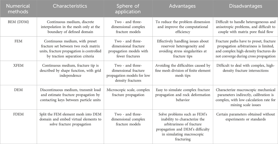
TABLE 1. Comparison of different numerical model methods for fracture propagation.
This article selects the well H in southern Sichuan and, based on previous research results, establishes a three-dimensional fracture network expansion model according to BEM (Boundary Element Method) and FVM (Finite Volume Method). It conducts field scale simulation of complex fracture networks in the whole well section, analyzes the evolution patterns of reservoir fracture networks under different natural fracture settings, stress differences, different natural fracture strength and different pumping modes, and provides technical support for crystallizing unconventional reservoir development plans.
2 Numerical model
The numerical simulation of hydraulic fracture network evolution is a very complicated process, which involves the coupling of four key processes: reservoir rock deformation, dynamic fluid distribution in fractures, fluid flow in fractures, and stress interaction between fractures. The research model in this article is based on the following assumptions:
(1) The reservoir rocks are planar and isotropic;
(2) Fracture propagation follows the theory of linear elastic fracture mechanics;
(3) The fluid flow inside fracture is laminar flow;
(4) Fracture propagate in either mode I or mixed mode I/II;
(5) Thermal effect is ignored.
2.1 Governing equation
The governing equation controls fracture length, width, height, shear slip, proppant transport and fluid pressure. To simplify the equation form, the combination parameters of Eqs 1, 2, 3 are introduced:
Where E is Young modulus;υis Poisson’s ratio;μ is fluid viscosity;KIC is rock toughness.
The elastic equation can be shown as Eq. 4:
Where σc is horizontal far-field stress; s is shear direction components; n is normal direction components; m is fracture unit number; Ann, Ans, Asn and Ass are hypersingular Green’s functions; T is 3-D influence coefficient; w is the fracture opening; u is fracture surface shear displacement; p is the fluid pressure; a is observation point; b is middle point of fracture line segment.
The elastic equation above is applicable to two-dimensional strain fracture. As for three-dimensional fractures, a threedimensional influence coefficient (Eq. 5) has to be introduced:
Where d is distance between observation point with midpoint of line segment;H is fracture height;αand βare empirical constants.
The viscous fluid flow in hydraulic fractures follows Poiseuille’s law, and the fluid velocity in hydraulic fractures can be expressed as Eq. 4:
Where q is fluid flow rate in fracture; ▽ is the gradient operator along the fracture path.
In the pseudo three-dimensional model, an extra consideration needs to be given to the height variation of each fracture unit. The average flow velocity inside fracture should be expressed as Eq. 7:
The mass balance equation for fracturing fluid flowing in hydraulic fractures is:
Where Q is fluid injection rate; δDirac delta function.
When the stress intensity factor reaches the fracture toughness of the rock, the fracture will expand forward, and the width of the fracture tip can be expressed as Eq. 9:
Where V is propagation velocity.
Under stress interaction, hydraulic fractures are considered as I-II mixed mode fractures, and the local fracture propagation deflection angle is as Eq. 10:
The calculation method of k is shown in Eq. 11:
Introducing the maximum circumferential stress criterion (Eq. 12) to reason:
Considering the migration of proppant, the mass balance equation for the flow process of fracturing fluid and solid particles in fractures can be respectively established as follows:
Where θis local fracture deflection angle; κis the ratio of Mode II stress intensity factor to mode I stress intensity factor; r and r0 are the distances from the given point to the fracture tip, at the current and last time steps, respectively; t is time.
When considering the influence of solid particle migration in hydraulic fracture propagation models, the original fluid lubrication Eq. 8 should be replaced by Eqs 13, 14.
If natural fractures are widely developed in reservoir, when hydraulic fractures meet natural fractures, the relative energy release rate is calculated to identify the preferential extension path of the fracture. The capacity release rate along the angle ε can be expressed as Eq. 15:
The calculation method of the modes I and II stress intensity factors are shown as Eqs 16, 17:
Where G is energy release rate; KⅠand KⅡare modes I and II stress intensity factors.
2.2 Boundary conditions
When multiple fractures propagate simultaneously, the sum of the injection amounts of fracturing fluid into each fracture is equal to the total injection amount, and the mass conservation equation can be expressed as Eq. 18:
The continuity of fracture inlet pressure can be expressed as Eq. 19:
In addition, assuming that the crack tip width and fluid flow are both 0, the mathematical expression is shown as Eq. 20, then:
2.3 Model solving
In order to effectively simulate the propagation process of multiple hydraulic fractures in segmented multi cluster fracturing of horizontal wells, all components of the model need to be coupled for calculation, and the solution process is shown in Figure 1. The reliability of this model has been proved in previous article (Chen et al., 2019), and the numerical solution of the model is precisely consistent with corresponding accurate solution.

FIGURE 1. Numerical model calculation flow chart of complex hydraulic fracture propagation.
3 Geological situation and parameters
The target well has been drilled to a depth of over 6,000 m, with a vertical depth of nearly 4,000 m and a horizontal section length of 1,900 m. The wellbore structure is shown in Figure 2. The completed drilling horizon is located in the Longmaxi Formation, with main lithology of the target layer being grayish black and black shale. The reservoir has developed micro fractures, exhibits low porosity and permeability, and has a logging porosity of 2.2%–4.5%, with an average value of 3.3%. Both organic and inorganic pores are highly developed. Organic pores are mainly developed in mineral frameworks, variously sized from several nanometers to hundreds nanometers, and shaped like subcircular, elliptical, pitted, and honeycomb. Inorganic pores have larger sizes and complex, diverse pore morphology. The brittleness coefficient of the reservoir ranges from 50.6% to 94.1%, with an average value of 77.1%, which means it has good brittleness and compressibility and is conducive to the formation of natural fractures and the fracturing stimulation in later process. Segmented multi-cluster fracturing technology is adopted for the well, with high-strength and high-displacement construction. By forming complex network fractures in the reservoir, the stimulation volume can be increased largely, so that good reservoir stimulation effectiveness can be achieved.
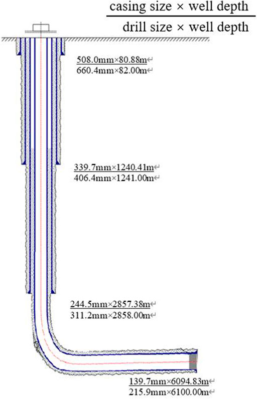
FIGURE 2. Schematic diagram of wellbore structure.
Based on the geological conditions of the horizontal well H and the fracturing construction parameters of the well, the input parameters of the model are determined as shown in Table 2, and the final numerical model is established as shown in Figure 3.
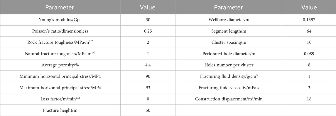
TABLE 2. The input parameters.
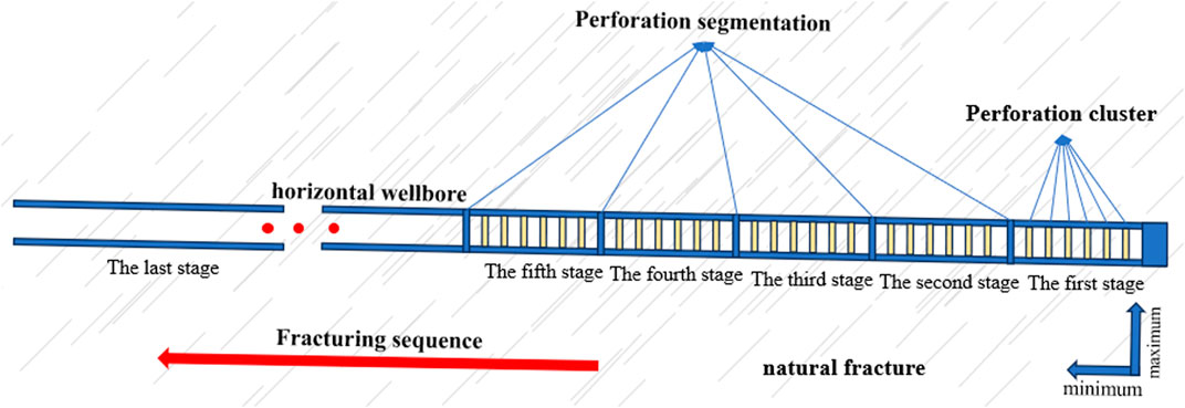
FIGURE 3. Schematic diagram of numerical model.
4 Analysis of influencing factors
The natural fractures in reservoirs have a significant impact on the formation of complex fracture networks through hydraulic fracturing. When high-pressure fluids introduced by hydraulic fracturing operations activate natural fractures in rocks, these natural fractures can be expanded, extended, interconnected, and form complex fracture networks, which increases the reservoir fracture control volume and improve the effectiveness of reservoir stimulation. However, in the process of hydraulic fracturing, a lot of factors can influence the interaction between hydraulic fractures and natural fractures. Clarifying the evolution laws of three-dimensional fracture networks under different influencing factors plays a guiding role in making plans to develop unconventional reservoir. This article uses the single factor analysis method to simulate the first five stages of fracturing in H by controlling variables, and analyzes the hydraulic fracture propagation law under different geological parameters (horizontal stress difference, natural fracture strike angle: the Angle between the natural fracture and the horizontal, and natural fracture strength) and different engineering parameters (fracturing construction displacement and fracturing fluid viscosity). The values of each parameter are shown in Table 3.

TABLE 3. Values of different influencing factors.
4.1 Geological parameter
4.1.1 Horizontal stress difference
In general, crustal stress can be divided into stress components in three main directions: maximum horizontal principal stress, minimum horizontal principal stress and vertical stress. Horizontal stress difference refers to the difference between the maximum horizontal principal stress and the minimum horizontal principal stress. The horizontal stress difference has a significant effect on controlling fracture direction, fracture propagating speed, and fracture width. This article conducts research on the propagation law of hydraulic fractures under five stress difference levels of 0 MPa, 3 MPa, 5 MPa, 8 MPa, and 10 MPa.
Keeping the minimum principal stress invariable and increasing the maximum principal stress of the reservoir to simulate the fracture propagation under different horizontal stress differences (Figure 4). When five stages of fracturing are carried out in sequence following the red arrows in Figure 4A, the middle fractures in the same section will generate compressive stress on the both ends of the fracture, causing the toe fractures to bend towards the far wellbore direction while the heel fractures to bend towards the opposite direction, which exhibit a clear stress shadow phenomenon.
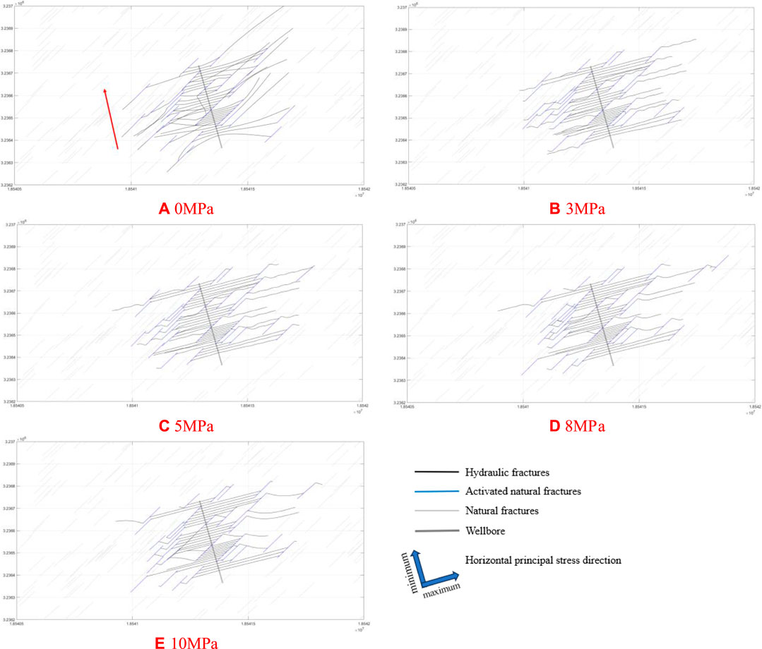
FIGURE 4. Fracture propagation under different horizontal stress differences.
The extension direction of hydraulic fractures is not limited by crustal stress, and the fracture tip points have high degrees of freedom. When hydraulic fractures meet natural fractures, they turn along the natural fractures. As the horizontal stress difference increases, the propagation of hydraulic fracture is constrained, and the stress shadow phenomenon weakens. When there is a horizontal stress difference, the propagation direction of hydraulic fracture is significantly controlled by crustal stress, extending nearly parallel to the maximum principal stress direction. In a state of high stress difference, hydraulic fracture activates natural fracture, which rapidly deflects the direction after reaching the end, and then continuing to extend along the direction of maximum horizontal principal stress, and connecting natural fractures that are farther away in that direction. However, in all cases of horizontal stress difference, there is no hydraulic fracture crossing the natural fracture.
Figure 5 shows the variation of fracture size under different horizontal stress differences. As the horizontal stress difference increases, the extension of hydraulic fracture is constrained, and the extension in the direction of the minimum horizontal principal stress is limited, resulting in a slight decrease in the total length of fractures and total SRV. However, in the direction of the maximum principal stress, further extension of hydraulic fracture connects farther natural fractures, leads to the increase of number of activated natural fracture (Figure 6), and helps to connect target reservoirs in remote well areas. At the same time, the extension of hydraulic fractures is constrained by the maximum principal stress, which makes the directionality stronger and reduces the intersection of hydraulic fractures within and between segments. This is beneficial for improving the effectiveness of reservoir stimulation.
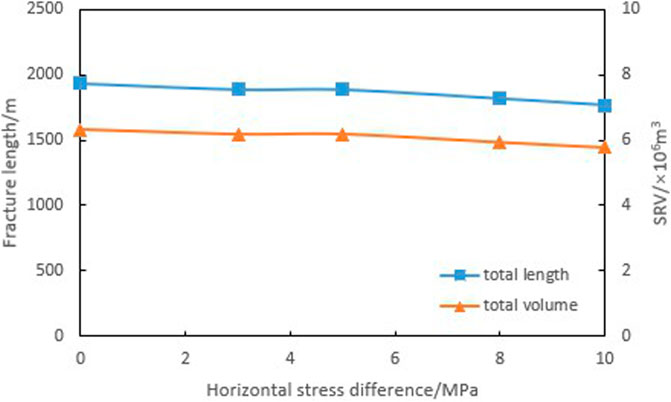
FIGURE 5. Fracture size under different horizontal stress differences.
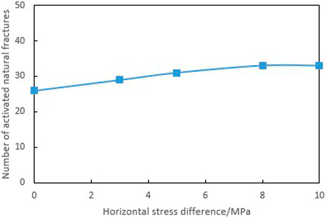
FIGURE 6. Number of activated natural fracture under different horizontal stress differences.
4.1.2 Natural fracture strike angle
Under different approach angles of hydraulic fractures and natural fractures, hydraulic fractures exhibit different propagation modes and final shapes. Hydraulic fractures tend to pass through natural fractures when the approach angle is large, and tend to turn along natural fractures while approach angle is small. When the approach angle is close to the middle value, the expansion behavior of hydraulic fractures after intersecting with natural fractures becomes more complex, and is usually accompanied by three modes: passing, opening, and branching. The target reservoir where well H is located has developed high dip angle (nearly vertical) conjugate fractures with strike angles of 45° and 135°. In this article, the study of hydraulic fracture propagation law under different natural fracture strike angles conditions is carried out by designing three different types of fractured reservoirs which develop natural fractures with strike angles of 45°, natural fractures with strike angles of 135°, and natural fractures with both strike angles of 45° and 135°.
Figure 7 shows the fracture propagation when a group of fractures and conjugate fractures exist simultaneously. When a reservoir develops a group of natural fractures, the fracture propagation patterns of the two types of natural fractures are basically the same. Hydraulic fractures mainly extend in the direction of the maximum horizontal principal stress. After the hydraulic fractures intersect with natural fractures, only a small portion of hydraulic fractures can continue to extend through natural fractures. Most hydraulic fractures activate natural fractures and continue to extend in the direction of maximum horizontal principal stress at the far end of the fractures. When two sets of conjugate fractures are developed in the reservoir, natural fractures constrain the extension of hydraulic fractures from two directions. Although natural fractures intersect with each other and increase the complexity of fractures, hydraulic fractures are difficult to effectively extend to the far wellbore area. As a result, it is difficult to obtain a larger fracture control volume.

FIGURE 7. Fracture propagation under different natural fracture strike angles.
Figure 8 indicates the changes in fracture size under different natural fracture conditions. When a group of natural fractures are developed in a reservoir, natural fractures with a strike angle of 135° have a stronger resistance to hydraulic fracture propagation than those with a strike angle of 45°. Under the same conditions, the total length of hydraulic fracture, the total SRV, and the number of activated natural fractures in reservoirs with fracture strike angle of 135° are all smaller than those in reservoirs with strike angle of 45°. When two sets of conjugated natural fractures are developed in the reservoir, the constraint of natural fractures on the expansion of hydraulic fractures increases, and comparing to only one set of natural fractures developed, there is a decrease in fracture length and SRV. Although conjugated natural fractures increase the probability of intersection between hydraulic fractures and natural fractures, also increase the number of activated natural fractures (Figure 9), obtaining higher fracture complexity, most hydraulic fractures are limited to the near wellbore zone, which is actually not conducive to increasing the fracture controlled reserve.
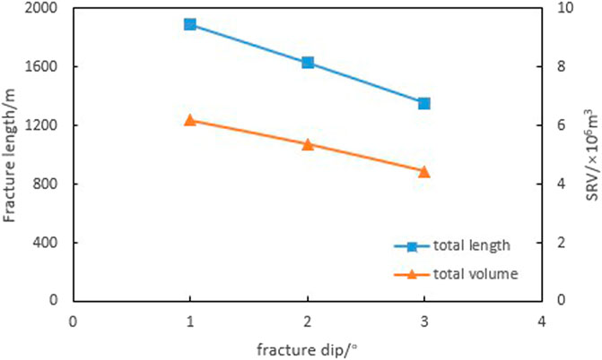
FIGURE 8. Fracture size under different natural fracture strike angles.

FIGURE 9. Number of activated and natural fractures under different strike angles of natural fractures.
4.1.3 Natural fracture strength
Fracture toughness characterizes the ability of a material to prevent fracture propagation and is a quantitative indicator of the toughness of a material. When the fracture size is fixed, the larger the fracture toughness value of the material is, the greater the critical stress required for the unstable propagation of the fracture will be. The fracture toughness of natural fracture cementitious mineral components determines the strength of natural fractures, as well as the propagation form of the intersection between hydraulic fractures and natural fractures, therefore it determines the final distribution form of three-dimensional fracture networks. Based on the distribution range of fracture toughness of the target reservoir, this article designed nine levels of natural fracture toughness, including 0.1 MP·m1/2, 0.3 MPa·m1/2, 0.5 MPa·m1/2, 0.8 MPa·m1/2, 1 MPa·m1/2, 1.5 MPa·m1/2, 2 MPa·m1/2, 2.5 MPa·m1/2, and 3 MPa·m1/2, to study the propagation law of hydraulic fractures under different natural fracture strength conditions.
Figure 10 shows the fracture propagation under different natural fracture toughness conditions. When the toughness is low, the intersection of hydraulic fractures and natural fractures will activate the natural fractures, and the hydraulic fractures will extend to the end of the natural fractures and continue to expand along the direction of the maximum horizontal principal stress. When the fracture toughness of natural fractures is high, hydraulic fractures directly pass through natural fractures and continue to expand. As the fracture toughness increases, the difficulty of activating natural fractures by hydraulic fractures increases as well, while the number of activated natural fractures decreases, and the propagation of fractures changes from complex to simple. Under extremely high natural fracture toughness conditions, the propagation of hydraulic fractures is almost unaffected by natural fractures, and only shows a slight deflection, presenting a nearly parallel state.
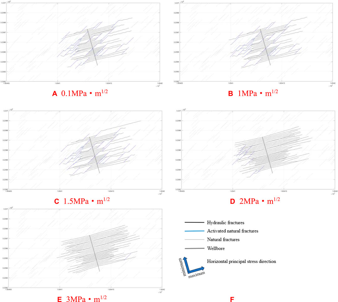
FIGURE 10. Fracture propagation under different natural fracture toughness conditions.
It can be seen from the fracture size under different natural fracture toughness conditions (Figure 11) that the activation of natural fractures is related to the comparative relationship between the fracture toughness of natural fractures and reservoir rocks. When the fracture toughness of natural fractures is less than 0.4 times that of rocks, the strength of natural fractures is at a lower level and can be activated indiscriminately by hydraulic fractures. As the fracture toughness of natural fractures increases, the difficulty of activating natural fractures increases as well, and the number of activated natural fractures decreases (Figure 12), so that the interference of natural fractures on the extension path of hydraulic fractures decreases, and the total length of fractures and total SRV increase. When the fracture toughness of natural fractures increases and exceeds the fracture toughness of reservoir rocks (2 MPa·m1/2), hydraulic fracture propagation is almost not interfered by natural fractures. So the figure indicates that when the number of activated natural fractures approaches to 0, the total length of fractures and total SRV tend to stabilize.

FIGURE 11. Fracture size under different natural fracture toughness conditions.

FIGURE 12. Number of activated natural fractures under different fracture toughness conditions.
4.2 Engineering parameters
4.2.1 Fracturing construction displacement
During the fracturing construction process, the selection of construction displacement is crucial for the effectiveness of hydraulic fracturing. When natural fractures develop, hydraulic fractures change direction and produce more natural fractures to form complex fracture networks. During this period, larger displacement, greater pump pressure and greater fluctuation of pump pressure are conducive to communicating more natural fractures and achieving better reservoir stimulation effectiveness. Based on the actual construction parameters on site, this article designed five levels of fracturing construction displacement: 6 m3/min, 10 m3/min, 14 m3/min, 18 m3/min, 20 m3/min, and conducted research on the hydraulic fracture propagation law under different fracturing construction displacement conditions.
The fracture propagation results under different fracturing construction displacement are shown in Figure 13. The results demonstrate that as the fracturing construction displacement increases, the extension length of the fracture in the direction of the maximum horizontal principal stress decreases slightly.

FIGURE 13. Fracture propagation under different fracturing construction displacement conditions.
Based on the fracture size and the number of activated natural fractures under different fracturing construction displacement conditions (Figures 14, 15), it can be seen that as the fracturing construction displacement increases, the total length of fractures, total SRV, and the number of activated natural fractures demonstrate a similar trend of increasing first and then decreasing. When the construction displacement is less than 10 m3/min, all of the three curves rise as fracturing construction displacement increase. However, when the fracturing construction displacement continues increasing, they decline gradually, and when the construction displacement volume reaches 18 m3/min, their values tend to be constant. Therefore, to achieve better reservoir stimulation results, the construction displacement range of the well should be 10–14 m3/min.
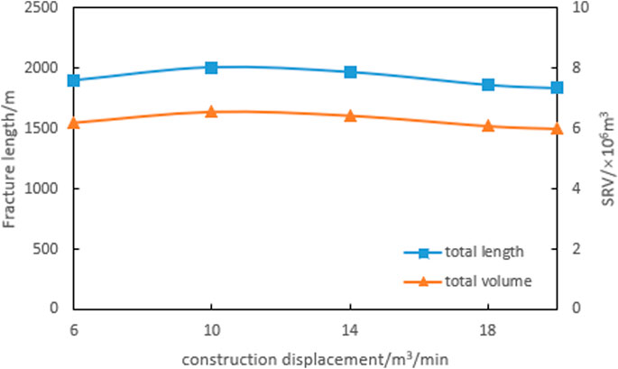
FIGURE 14. Fracture size under different fracturing construction displacement conditions.
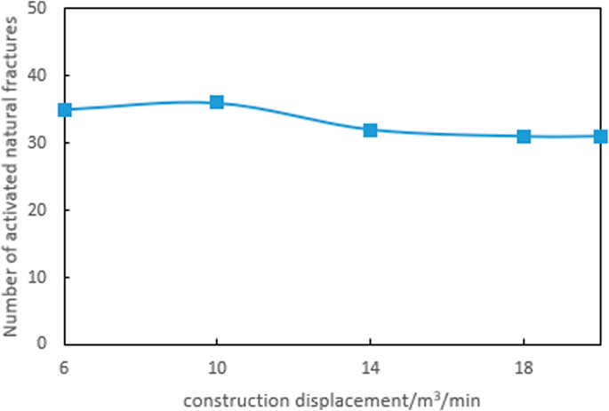
FIGURE 15. Number of natural fractures activated under different fracturing construction displacement conditions.
4.2.2 Fracturing fluid viscosity
The rheological properties of fracturing fluid have a significant impact on the effectiveness of hydraulic fracturing construction. When other conditions are same, low viscosity fracturing fluid is suitable for creating long fractures and communicating more natural fractures, while high viscosity fracturing fluid is suitable for creating wide fractures and obtaining larger oil and gas seepage channels. Reasonable selection of fracturing fluid viscosity plays an important role in the final reservoir stimulation effectiveness. Based on the types and rheological parameters of fracturing fluids used in on-site construction, this article designs seven levels of fracturing fluid viscosity: 3 mPa·s, 5 mPa·s, 8 mPa·s, 10 mPa·s, 30 mPa·s, 60 mPa·s, and 100 mPa·s, and conducts a study on the hydraulic fracture propagation law under different fracturing fluid viscosity conditions.
Figure 16 indicates the results of fracture propagation under different fracturing fluid viscosity. It can be seen from the figure that the viscosity of the fracturing fluid significantly affects the fracture morphology as well. As the viscosity of the fracturing fluid increases, the extension length of hydraulic fractures, the distribution range of fractures, and the number of activated natural fractures decrease significantly. Low viscosity fracturing fluid reduces the resistance of the fluid inside the fracture, causing the fluid to spread further and form long-narrow fractures. Meanwhile, as the viscosity of the fracturing fluid increases, both the net pressure and induced compressive stress of the fracture increase, leading to the first segment of fracture bending towards the toe with larger amplitude. When the stress shadow phenomenon becomes obvious, the high viscosity fracturing fluid forms relative short and wide fractures.
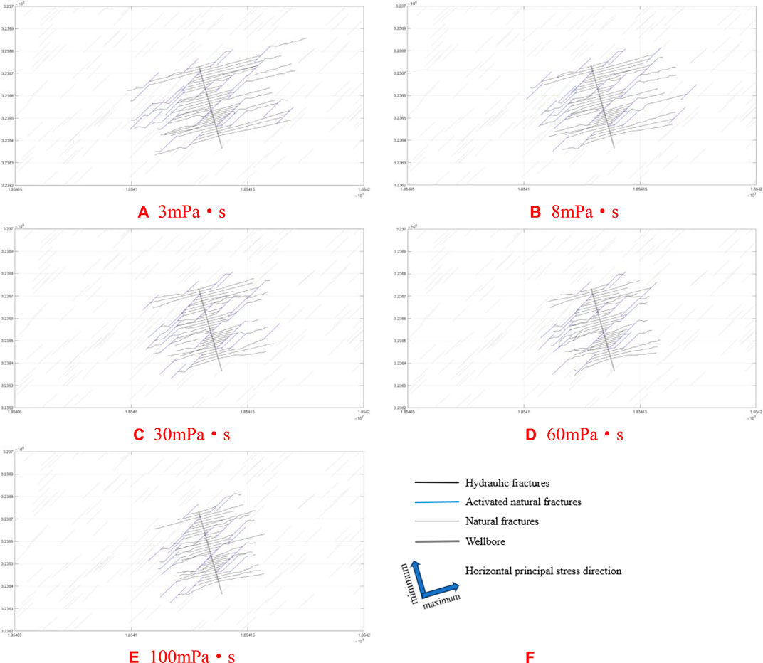
FIGURE 16. Fracture propagation under different fracturing fluid viscosity conditions.
According to Figures 17, 18, as the viscosity of the fracturing fluid increases, the total length of fractures, total SRV, and the number of activated natural fractures all tend to decrease. Minimizing the viscosity of the fracturing fluid while meeting the requirements of sand carrying design to connect the far end reservoir and activate more natural fractures can achieve better reservoir reconstruction effectiveness.

FIGURE 17. Fracture size under different fracturing fluid viscosity conditions.
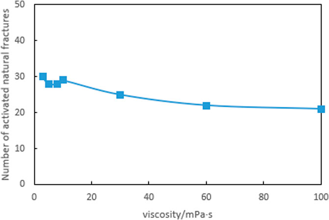
FIGURE 18. Number of natural fractures activated under different fracturing fluid viscosity conditions.
5 Conclusion
(1) The horizontal stress difference has relatively small effect on fracture size, showing a negative correlation with it. A large horizontal principal stress difference constrains the expansion of hydraulic fractures, strictly follows the phenomenon that expanding along the direction of maximum horizontal principal stress and weakening the stress shadow, makes the fractures have stronger directivity, reducing pressure channeling within and between segments. The well trajectory should be parallel to the minimum horizontal principal stress setting, which is conducive to improving the effectiveness of reservoir stimulation.
(2) In reservoirs which develop natural fractures, the natural fractures will hinder the expansion of hydraulic fractures, and the conjugate fractures will interfere with the expansion of hydraulic fractures from both directions. Although natural fractures are interlacing with each other and increase the complexity of fractures, the fractures are limited to the near-well zone, so that the fracture size will be smaller than that of a certain group of fractures developed separately, which is not conducive to improving the reservoir stimulation effectiveness.
(3) The fracture size is positively correlated with the strength of natural fractures. When the fracture toughness of natural fractures is low, natural fractures are easily activated and the complexity of fractures is strong. When the stress intensity factor of natural fractures is large, natural fractures are easily penetrated directly and the distribution of fractures is simple. However, when the fracture toughness of natural fractures is excessively large, the fracture size is almost unaffected by the strength of natural fractures.
(4) As the fracturing construction displacement increases, the fracture size and the number of activated natural fractures show a pattern of increasing at first and then decreasing. A suitable construction displacement not only helps to break through the obstacles of natural fractures and form a more complex distribution of fractures, but also helps to obtain a larger reservoir stimulation volume. The optimal construction displacement for this well is 10–14 m3/min.
(5) Low viscosity fracturing fluid is suitable for forming long and narrow fractures, while high viscosity fracturing fluid forms relatively short and wide fractures. To overcome the obstruction of natural fractures, connect with remote reservoir, form complex fracture networks and achieve better reservoir stimulation effectiveness, low viscosity fracturing fluid should be used as much as possible to meet the requirements of sand carrying design Kresse and Weng, 2017, National Resources Canada, 2016.
Data availability statement
The original contributions presented in the study are included in the article/supplementary material, further inquiries can be directed to the corresponding author.
Author contributions
XC: Software, Supervision, Writing–original draft. YH: Writing–original draft, Writing–review and editing. YL: Methodology, Validation, Writing–review and editing. CS: Software, Writing–review and editing.
Funding
The author(s) declare financial support was received for the research, authorship, and/or publication of this article. The research was supported by 1) the National Natural Science Foundation of China (Grant no. U19A2043), 2) Science and Technology Cooperation Project of the CNPC-SWPU Innovation Alliance, 3) Supported by Sichuan Science and Technology Program 2023NSFSC0933.
Conflict of interest
Author CS was employed by PetroChina Southwest Oil and Gasfield Company.
The remaining authors declare that the research was conducted in the absence of any commercial or financial relationships that could be construed as a potential conflict of interest.
Publisher’s note
All claims expressed in this article are solely those of the authors and do not necessarily represent those of their affiliated organizations, or those of the publisher, the editors and the reviewers. Any product that may be evaluated in this article, or claim that may be made by its manufacturer, is not guaranteed or endorsed by the publisher.
References
Belytschko, T. (1999). Elastic crack growth in finite elements with minimal remeshing. Int. J. Numer. Methods Eng. 45 (5), 601–620. doi:10.1002/(sici)1097-0207(19990620)45:5<601::aid-nme598>3.0.co;2-s
Biewick, L. R. (2014). Map of assessed coalbed-gas resources in the United States. Washington, D: U.S. Department of the Interior.
Bp, (2014). BP energy outlook 2035. [2016-06-28] http://wwwbpcom/en/global/corporate/about-bp/energy-economics/energy-outlookhtml.
Chen, X., Li, Y., Zhao, J., Xu, W., and Fu, D. (2017a). Numerical investigation for simultaneous growth of hydraulic fractures in multiple horizontal wells. J. Nat. Gas Sci. Eng. 51, 44–52doi. doi:10.1016/j.jngse.2017.12.014
Chen, X., Zhao, J., Li, Y., Yan, W., and Zhang, X. (2019). Numerical simulation of simultaneous hydraulic fracture growth within a rock layer: implications for stimulation of low permeability reservoirs. J. Geophys. Res. Solid Earthdoi 124, 13227–13249. doi:10.1029/2019jb017942
Chen, X., Zhao, J., Yan, W., and Zhang, X. (2018). Numerical investigation into the simultaneous growth of two closely spaced fluid-driven fractures. SPE Journaldoi 24, 274–289. doi:10.2118/194188-pa
Chen, Z., Jeffrey, R. G., Zhang, Xi, and Kear, J. (2017b). Finite-element simulation of a hydraulic fracture interacting with a natural fracture. SPE J. 22 (1), 219–234. doi:10.2118/176970-pa
China Business Industry Research Institute (2022). TOP10 global energy consumers in 2022 https://m.163.com/dy/article/HBGTR4SU051481OF.htm1.
Cocco, M. J., and Ernandez, J. E. (2013). Reservoir characterization of junin area, orinoco oil belt region. Venezuela. SPE 171136-MS. Medellín, Colombia.
Detournay, E. (2004). Propagation regimes of fluid-driven fractures in impermeable rocks. Int. J. Geomechanics 4 (1), 35–45. doi:10.1061/(asce)1532-3641(2004)4:1(35)
East, L., Soliman, M. Y., and Augustine, J. (2011). Methods for enhancing far-field complexity in fracturing operations. SPE Production8.Operations 26 (3), 291–303. doi:10.2118/133380-pa
Fletcher, P., Cobos, S., Jaska, C., Forsyth, J., Crabtree, M., and Gaillard, N., (2012). Improving heavy oil recovery using an enhanced polymer system. Tulsa, Oklahoma, USA: Spe Improved Oil Recovery Symposium.
Hamidi, F., and Mortazavi, A. (2012). “Three dimensional modeling of hydraulic fracturing process in oil reservoirs,” in 46th US rock mechanics/geomechanics symposium (Chicago, Illinois),
Hartenergy, (2015). Unconventional oil & gas center. http://www.hartenergy.com/Midstream/Data-Services/.
Hou, B., Wu, A., and Chang, Z., (2021). Experimental study on vertical propagation of fractures of multi-sweet of spots shale oil reservoir. Chin. J. Geotechnical Eng. 43 (7), 1322–1330. doi:10.11779/CJGE202107018
Huang, L., Dontsov, E., Fu, H., Lei, Y., Weng, D., and Zhang, F. (2022). Hydraulic fracture height growth in layered rocks: perspective from DEM simulation of different propagation regimes. Int. J. Solids Struct. 238, 111395. doi:10.1016/j.ijsolstr.2021.111395
Huang, L., He, R., Yang, Z., Tan, P., Chen, W., Li, X., et al. (2023c). Exploring hydraulic fracture behavior in glutenite formation with strong heterogeneity and variable lithology based on DEM simulation. Eng. Fract. Mech. 278, 109020. doi:10.1016/j.engfracmech.2022.109020
Huang, L., Liu, J., Zhang, F., Donstov, E., and Damjanac, B. (2019). Exploring the influence of rock inherent heterogeneity and grain size on hydraulic fracturing using discrete element modeling. Int. J. Solids Struct. 176, 207–220. doi:10.1016/j.ijsolstr.2019.06.018
Huang, L., Liu, J., Zhang, F., Fu, H., Zhu, H., and Damjanac, B. (2020). 3D lattice modeling of hydraulic fracture initiation and near-wellbore propagation for different perforation models. J. Pet. Sci. Eng. 191, 107169. doi:10.1016/j.petrol.2020.107169
Huang, L., Tan, J., Fu, H., Liu, J., Chen, X., Liao, X., et al. (2023a). The non-plane initiation and propagation mechanism of multiple hydraulic fractures in tight reservoirs considering stress shadow effects. Eng. Fract. Mech. 292, 109570. doi:10.1016/j.engfracmech.2023.109570
Huang, L., Tan, J., Fu, H., Liu, J., Chen, X., Liao, X., et al. (2023b). The non-plane initiation and propagation mechanism of multiple hydraulic fractures in tight reservoirs considering stress shadow effects. Eng. Fract. Mech. 292, 109570. doi:10.1016/j.engfracmech.2023.109570
Hunsweck, M. J., Shen, Y., and Lew, A. J. (2013). A finite element approach to the simulation of hydraulic fractures with lag. Int. J. Numer. Anal. Methods Geomechanics 37 (9), 993–1015. doi:10.1002/nag.1131
Jia, C., Zou, C., Li, J., Li, D., Zheng, M., et al. (2012). Assessment criteria, main types, basic features and resource prospects of the tight oil in China. Acta Pet. Sin. 33 (3), 343–350. doi:10.7623/syxb201203001
Kresse, O., and Weng, X. W. (2017). Numerical modeling of 3D hydraulic fractures interaction in complex naturally fractured formations. J . Rock Mech. Rock Eng. 12, 3863–3881.
Kuuskraa, V., Stevens, S., and Moodhe, K. (2013). World shale gas and shale oil resources assessment. Available at: http://www.eia.gov/conference/2013/pdf/presentations/kuuskraa.pdf.
Lecampion, B., Bunger, A., and Zhang, X. (2017). Numerical methods for hydraulic fracture propagation: a review of recent trends. J. Nat. Gas Sci. Eng. 49, 66–83. doi:10.1016/jjngse.2017.10.012
Loucks, R. G., Reed, R. M., Ruppel, S. C., and Hammes, U. (2012). Spectrum of pore types and networks in mudrocks and a descriptive classification for matrix-related mudrock pores. AAPGBulletin 96 (6), 1071–1098. doi:10.1306/08171111061
Loucks, R. G., Ruppel, S. C., Wang, X., Ko, L., Peng, S., and Zhang, T., (2017). Pore types, pore-network analysis, and pore quantification of the lacustrine shale-hydrocarbon system in the Late Triassic Yanchang Formation in the southeastern Ordos Basin, China. China jl. Interpret. 5 (2), SF63–SF79. doi:10.1190/int-2016-0094.1
Mayerhofer, M., Lolon, E., Warpinski, N., Cipolla, C., Walser, D., Rightmire, C., et al. (2008). What is stimulated rock volume. SPE, 12 119890. doi:10.2118/119890-MS
Moes, N., and Belytschko, T. (1999). A finite element method for crack growth withoutremeshing. Int. J. Numer. Methods Eng. 46, 131–150. doi:10.1002/(sici)1097-0207(19990910)46:1<131::aid-nme726>3.0.co;2-j
National Resources Canada (2016). North American tight oil. Available at: http://www.nrcan.gc.ca/energy/sources/crude/2114#oil1.
Tan, P., Fu, S. H., Chen, Z. W., and Zhao, Q. (2023). Experimental investigation on fracture growth for integrated hydraulic fracturing in multiple gas bearing formations. Geoenergy Sci. Eng. 231, 212316. doi:10.1016/j.geoen.2023.212316
Tan, P., Pang, H., Zhang, R., Jin, Y., Zhou, Y., and Kao, J., (2020). Experimental investigation into hydraulic fracture geometry and proppant migration characteristics for southeastern Sichuan deep shale reservoirs. J. Pet. Sci. Eng. 184, 106517. doi:10.1016/j.petrol.2019.106517
The Unconventional Oil Subgroup of the Resources & Supply Task Group (2011). Potential of North American Unconventional Oil Resource, Western Siberia, Russia.: The NPC North American Resource Development Study.
Valenza, J. J., Drenzek, N., Marques, F., Pagels, M., and Mastalerz, M. (2013). Geochemical controls on shale microstructure. Geology 41 (5), 611–614. doi:10.1130/g33639.1
Wang, H., Ma, F., Tong, X., Liu, Z., Zhang, X., Wu, Z., et al. (2016). Assessment of global unconventional oil and gas resources. PETROLEUM Explor. Dev. 43 (6), 925–940. doi:10.1016/s1876-3804(16)30111-2
Wang, L., Wang, S., Zhang, R., Wang, C., Xiong, Y., Zheng, X., et al. (2017). Review of multi-scale and multi-physical simulation technologies for shale and tight gas reservoirs. J. Nat. Gas Sci. Eng. 37 (37), 560–578. doi:10.1016/j.jngse.2016.11.051
Wang, R., Hu, Z., Liu, J., Wang, X., Gong, D., Tao, Y., et al. (2018). Comparative analysis of characteristics and controlling factors of fractures in marine and continental shales: a case study of the Lower Cambrian in Cengong area, northern Guizhou Province. Oil Gas Geol. 39 (4), 631–640.
Wang, Y. (2021). The exploration and development prospects of unconventional oil and gas resources in China are broad. Petroleum Knowledge 6, 14–15.
Xie, J., Tang, J., Rui, Y., Fan, Y., Zuo, L., Chen, X., et al. (2020). A 3-D hydraulic fracture propagation model applied for shale gas reservoirs with multiple bedding planes. Eng. Fract. Mech. 228, 106872. doi:10.1016/j.engfracmech.2020.106872
Yamamoto, K., Shimamoto, T., and Maezumi, S. (1999). The SPE asia pacific oil and gas conference and exhibition jakarta. Indonesia: SPE.Development of a true 3D hydraulic fracturing simulator
Zou, C., Tao, S., Hou, L., et al. (2014a). Unconventional petroleum geology. Beijing, China: Geological Publishing House.
Keywords: unconventional reservoir, fracture network, numerical simulation, geological factors, engineering factors
Citation: Chen X, Huang Y, Li Y and Shen C (2024) Numerical simulation study on evolution law of three-dimensional fracture network in unconventional reservoirs. Front. Energy Res. 11:1337069. doi: 10.3389/fenrg.2023.1337069
Received: 12 November 2023; Accepted: 27 December 2023;
Published: 12 January 2024.
Edited by:
Peng Tan, CNPC Engineering Technology R&D Company Limited, ChinaReviewed by:
Zaile Zhou, Yangtze University, ChinaDawei Zhou, China University of Petroleum, Beijing, China
Copyright © 2024 Chen, Huang, Li and Shen. This is an open-access article distributed under the terms of the Creative Commons Attribution License (CC BY). The use, distribution or reproduction in other forums is permitted, provided the original author(s) and the copyright owner(s) are credited and that the original publication in this journal is cited, in accordance with accepted academic practice. No use, distribution or reproduction is permitted which does not comply with these terms.
*Correspondence: Yitao Huang, aHVhbmd5aXRhbzUxOEAxNjMuY29t