 Qinwei Wang1
 Wenting Chen
 Yonggang Lin
 Hongwei Liu
- 1State Key Laboratory of Crane Technology, Yanshan University, Qinhuangdao, Hebei, China
- 2State Key Laboratory of Fluid Power and Mechatronic Systems, Zhejiang University, Hangzhou, Zhejiang, China
- 3National-Local Joint Engineering Research Center for Advanced Manufacturing, Forming Technology and Equipment, Yanshan University, Qinhuangdao, China
In recent years, wind turbines are becoming larger, which will exacerbate the complexity of loads Complex load change affect the output power quality and wind turbine service life so that must be studied. Pitch control is usually used to reduce wind turbine load. In this paper, based on the Light Detection and Ranging (LiDAR) technology and incremental feedforward control theory, an incremental feedforward collective pitch controller is proposed. The controller can be directly superimposed on the traditional collective pitch controller so that the incremental pitch angle can fully compensate wind influence. The effectiveness of the controller is verified by multi-software platform joint simulation and hardware-in-the-loop experiment. The results show that the controller can effectively reduce the wind turbine power and load fluctuation when the variation trend of wind speed in the rotor plane estimate by LiDAR data is the same as the actual wind speed.
1 Introduction
With the deepening of wind power research, it has been found that the complex load changes of wind turbines caused by wind fluctuations and turbulence characteristics will adversely affect the output power quality and service life of wind turbines (Yuan et al., 2020). Currently, a wind turbine usually uses pitch control to reduce the load on the blades and ensure a smooth output of power. Therefore, in order to cope with these problems, it is necessary to optimize the control of the pitch angle and rotational speed of the wind turbine.
The application of Light Detection and Ranging (LiDAR) introduced wind speed information about reaching the plane to the wind turbine control system. Scholbrock et al. (2016) believed that by introducing this input quantity, the controller control performance could be optimized, and it might also reduce the load of the wind turbine and increase the power generation of the wind turbine. Khaniki et al. (2018) found that LiDAR-assisted feedforward control was better than pseudo-feedforward control. In summary, the collective pitch control technology based on the LiDAR wind measurement can be considered to reduce speed fluctuations and structural loads in the full-load area of wind turbines. It has been proposed that the LiDAR-predicted wind speed can be combined with pitch control to reduce the load of the wind turbine and extend the life of the wind turbine by 6–8 years by some researchers (Mikkelsen, 2014). However, some researchers have pointed out that the excessive pursuit of reducing load and increasing life faces the problem of reducing the net annual energy produced in wind energy (Mathur et al., 2017).
For the moment, the collective pitch control technology based on the LiDAR wind measurement currently has two mainstream research directions, one of which is to completely replace the traditional feedback control technology of the wind turbine. The collective pitch signal has been completely processed using the corresponding algorithm of the wind data measured by LiDAR, such as LiDAR-assisted control (David and Steffen, 2016), collective feedforward pitch control (Haizmann et al., 2015), model predictive control (Bottasso et al., 2014), radial basis function neural network control (Han et al., 2018a), and fuzzy control (Van et al., 2015).
Another research direction has been to keep the original controller unchanged and superimpose a feedforward pitch controller, such as the wind turbine feedforward-feedback H2 optimal control based on the LiDAR wind measurement (Dunne and Pao, 2016), the LiDAR wind measurement feedforward pitch control combined with the cabin acceleration feedback (Yamaguchi et al., 2020), the joint control mode of the baseline feedback control enhanced by gain scheduling feedforward control based on the pseudo-LiDAR wind measurement (Bao et al., 2018), feedforward controller based on neural network catenary data weights (Han et al., 2018b), and the feedforward control carried out by looking up the static pitch angle curve table after using the LiDAR wind speed to estimate the effective wind speed of the rotor plane (Schlipf et al., 2015).
Through the experiments of different scholars, the positive effect of LiDAR on wind turbines has been proved. For example, the experimental results under different turbulence conditions show that the adaptive control method, that is, the radial basis neural network combined with the finite impulse response filter (RBFNNFIR) based on the LIDAR wind measurement (Jia et al., 2021), can effectively reduce the fluctuation of the generator speed and the maximum value of the load moment at the beginning of the blade. The optimal control of the prediction algorithm combining the linear wind turbine model and LiDAR-simulated wind disturbance can be applied to the non-linear wind turbine model, which can effectively improve the control performance, reduce the fluctuation of generator speed, and meet the pitch activity control limitation (Bao and Yue, 2022).
In this paper, the incremental feedforward collective pitch control method is used to calculate the increment of the pitch angle using the wind speed disturbance increment measured by LiDAR to reduce the impact of wind on the feedback given. This control method can realize the smooth transition of the pitch angle in the feedforward cut-out process. Furthermore, the wind turbine state change caused by the wind speed change is offset by the feedforward incremental pitch angle, which reduces the impact of the wind speed change on the wind turbine. The effectiveness of the proposed method is verified through joint simulation and hardware-in-the-loop experiment.
2 Incremental feedforward collective pitch controller
2.1 Design the incremental feedforward collective pitch control scheme
By using the LiDAR wind measurement technology, the wind speed time series of the rotor plane can be estimated according to the wind information measured by LiDAR, that is, the dynamic change of the wind can be measured. Therefore, the dynamic wind information measured by LiDAR can be used to calculate the feedforward pitch angle to compensate for the change in the load of the wind turbine caused by the wind change.
This paper proposes a wind turbine incremental feedforward collective pitch control method based on LiDAR prediction wind information. In this method, the calculated value is a given value, without artificially adjusting the proportion of the feedforward given in the total pitch angle. So, the controller designed using this control method can be directly added to the original collective pitch controller as a module. The specific steps are described as follows: first, the dynamic model of the wind turbine is established according to the dynamic characteristics. Then, based on the wind information measured by LiDAR, the wind disturbance increment signal about to reach the rotor plane is estimated. Finally, the wind signal in the wind turbine aerodynamic torque model is linearized to design the controller.
The collective pitch control of the wind turbine is shown in Figure 1. The input pitch angle
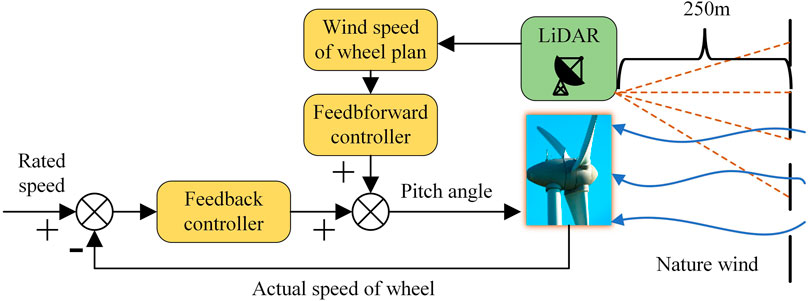
FIGURE 1. Incremental feedforward control assisted collective pitch baseline controller.
Eq. 1 represents the overall equation of the pitch controller.
where
Considering the short sampling interval, the four-order of
where
The following section will consider the FAST 5-MW wind turbine in FAST software as an example to provide the derivation method of this incremental feedforward collective pitch controller.
2.2 Theoretical derivation of incremental feedforward controllers
2.2.1 Onshore wind turbine baseline collective pitch controller
The baseline collective pitch controller is derived from the dynamic model of the wind turbine. Finally, the variable proportional gain PI feedback controller (Jonkman et al., 2009a) is obtained to control the constant speed of the generator. The dynamic model of the wind turbine wind turbine rotor can be expressed as
where
Generator torque can be expressed as
where
The aerodynamic torque of the wind turbine can be expressed as
where
The linearization equation of generator torque and the wind turbine rotor at the rated speed can be expressed as
where
For PID control, the feedback pitch angle
where
2.2.2 Theoretical derivation of the incremental feedforward collective pitch controller
The wind turbine rotor dynamic model of the FAST’s 5-MW wind turbine is obtained under stable wind speed. The incremental feedforward collective pitch controller can be derived. First of all, wind speed in Eq. 5 is to be substituted by the effective rotor plane wind speed measured by LiDAR. Therefore, Eq. 9 can be obtained.
The wind speed signal in Eq. 9 is linearized at the working point, and the high-order infinitesimal term of the wind speed change is ignored. Simulating Eqs 3, 7, 9, we can obtain the following equation:
The incremental feedforward collective pitch controller can be obtained using Eq. 10. Before that, some assumptions need to be made:
The speed of the wind turbine has been stabilized through the feedback pitch angle
In this steady state, the change in the rotor speed caused by the wind speed disturbance is completely offset by the feedforward pitch angle
(1) The LiDAR measurement sampling time is small enough, and the sampling time can be aligned with the sampling time of the wind turbine’s own sampling system.
(2) The effective rotor plane wind speed estimated by the wind speed measured by LiDAR is exactly the same as the actual wind speed.
(3) The wind energy utilization coefficient model of the wind turbine is a collective and common mathematical simplification model.
On the basis of the assumption condition (1), that is,
According to the assumptions, Eq. 11 can be used to obtain the incremental pitch angle (2). This controller can be added as a module to the traditional collective pitch controller to obtain Eq. 1, the incremental feedforward collective pitch controller. Furthermore, the calculated value is the given value, without artificially adjusting the proportion.
2.3 LiDAR wind measurement data pre-processing
LiDAR can only measure the wind information at a certain distance in front of the wind turbine rotor. However, for the wind turbine control, the best predicted wind information is the wind information that will arrive at the rotor plane exactly in the time required by the wind turbine pitch mechanism. Therefore, the LiDAR measurement needs to be processed accordingly (as shown in Figure 2). Then, the pitch control is made in advance using the wind information time series estimated in the rotor plane.
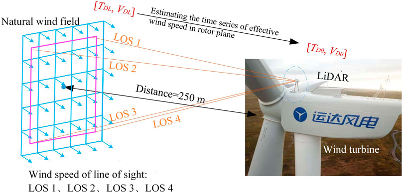
FIGURE 2. Diagram of LiDAR wind data preprocessing.
Under the condition that LiDAR has built in the line-of-sight wind speed and wind field reconstruction method, the main aim is to estimate the effective rotor plane wind speed by inverting the wind speed at the measurement point by processing the wind frequency, amplitude, and phase.
First, the filter is used to deal with the wind speed frequency measured by LiDAR so that the frequency unrelated to the wind speed of the rotor plane can be filtered (Schlipf, 2015). The filtering expression is shown in Eq. 12.
Schlipf (2015) proposed a method for determining constants,
Second, the wind speed amplitude of the rotor plane is estimated using the wind speed attenuation model of the induction area of the wind turbine (Zhang et al., 2021). Specific details are shown in Eq. 13.
where
Finally, the wind speed phase estimation in the rotor plane mainly refers to the time when LiDAR measures the wind speed to reach the rotor plane. Its calculation method contains the use of Eq. 13 and differential equations for separable variables.
where
The rotor plane effective wind time series is estimated using the above method (Zhang et al., 2022), as follows:
where
3 FAST/Simulink joint simulation
3.1 Simulation platform
As shown in Figure 3, FAST [an open-source software tool from the U.S. Department of Energy’s National Renewable Energy Laboratory (NREL)] provides mathematical models and kinetic operations for a 5-MW onshore wind turbine, and TurbSim to simulate the wind farm, while FAST and Simulink are connected to exchange data via interfaces. After the control system built in Simulink takes the input signal from FAST, the control module calculates the control target which is fed into the FAST 5-MW wind turbine model. The wind turbine makes corresponding actions accordingly. The parameters of the 5-MW wind turbine are shown in Table 1.
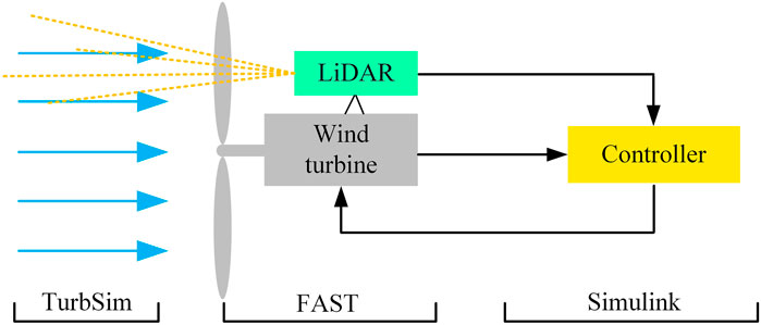
FIGURE 3. FAST/Simulink joint simulation diagram.

TABLE 1. Parameters of the 5-MW wind turbine.
3.2 Simulation results under ideal estimation of the rotor plane wind speed
During the simulation, it is assumed that the rotor plane wind speed estimated by LiDAR is the same as the actual wind speed of the rotor plane. In the application of feedforward controllers, the given signal increments are corrected so that the given paddle pitch angle signal of the feedforward controller has the least impact on the baseline feedback controller. Two correction methods are considered during the simulation. One is to limit the amplitude of the feedforward signal, and the other is to consider the correction coefficient method in the baseline collective pitch controller (Zhang et al., 2022).
The amplitude limiting method is used to increase the amplitude limitation for the feedforward signal and observe whether the control presetting of the baseline feedback controller has enough stiffness to quickly restore the stability after the feedforward control gives a small perturbation. When a step wind speed is given as 12 m/s–15 m/s, the incremental feedforward controller limitation is, respectively, set as 0.025 rad, 0.050 rad, 0.075 rad, and 0.1 rad, and the system response is shown in Figure 4. The overall control effect of the wind turbine with limiting is better than the state without limitation. The generator speed fluctuation performance is the best in amplitude limitation being 0.1 rad. The turbine power and edgewise moment are in good condition in a limitation of 0.050 rad. Fore-aft moment and fore-aft shear force have the most pronounced volatility improvement in a limitation of 0.075 rad. With comprehensive consideration, the limitation is determined to be 0.075 rad.
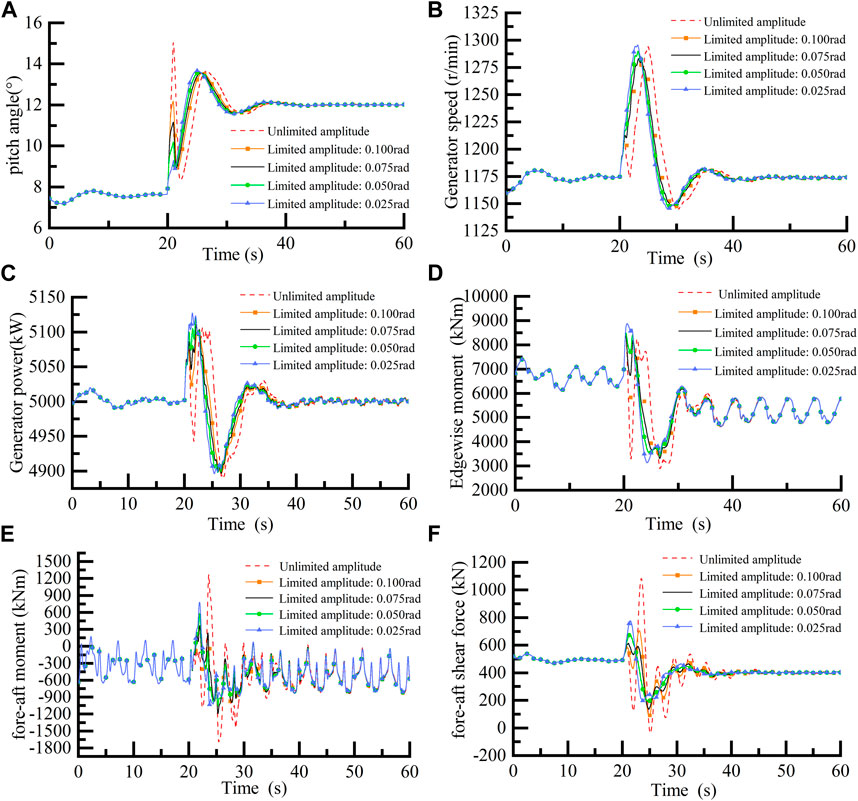
FIGURE 4. Wind turbine response with different limit values.
When the given step wind speed is 12–18 m/s, it can be seen from Figure 5 that the pitch angle has a relatively large fluctuation under feedforward control with the correction factor or unlimited amplitude. However, the pitch angle has a relatively gentle variation with the 0.075-rad amplitude limitation. Therefore, in the process of adding the incremental feedforward controller into the wind turbine baseline collective pitch, it needs to limit the given incremental feedforward pitch angle amplitude to the range of 0.075 rad.
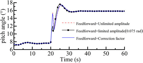
FIGURE 5. Wind turbine response under step wind speed.
Referring to the IEC Standard, the given gust signal and wind turbine response are shown in Figure 6. The LiDAR gust warning function is also added to the incremental feedforward controller, that is, when the wind speed measured by LiDAR is greater than the cut-in wind speed 3 m/s, or less than the rated wind speed 11.4 m/s, the pitch angle of the wind turbine is directly set to
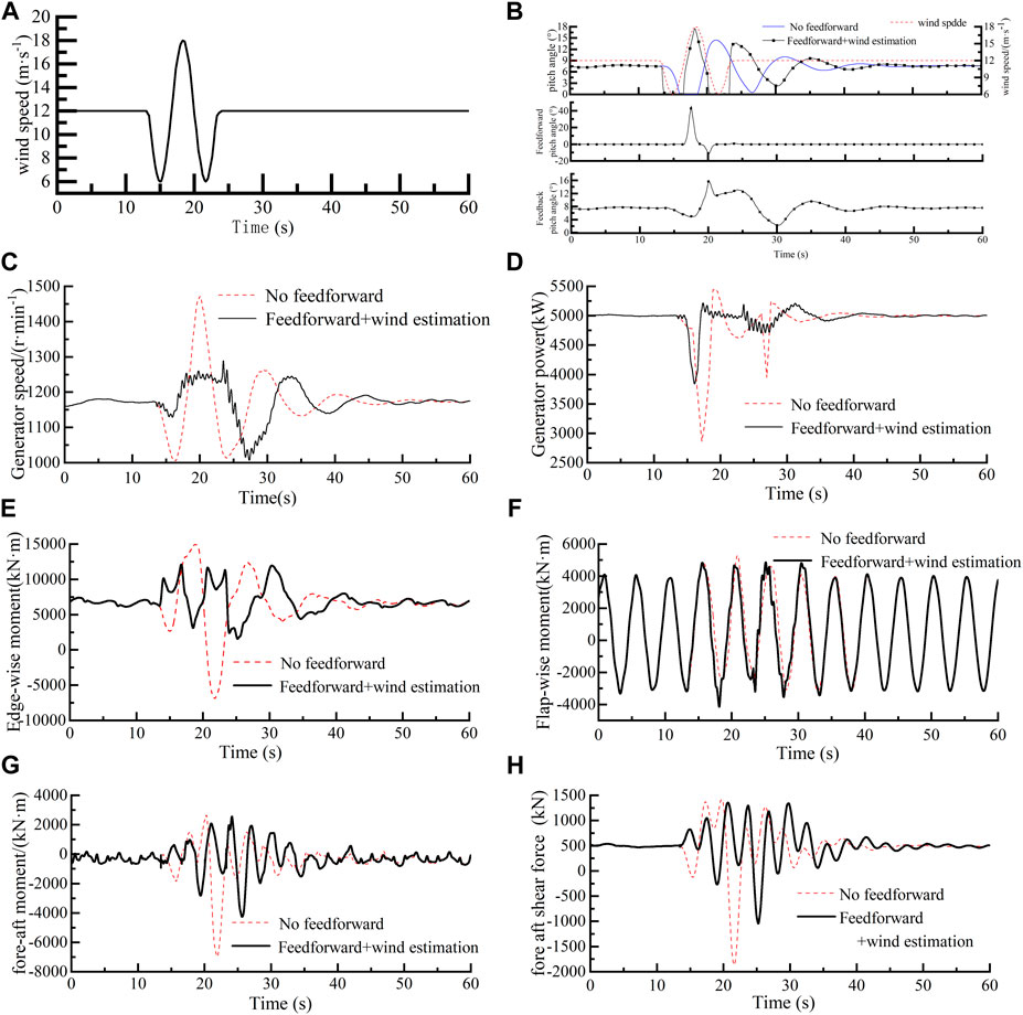
FIGURE 6. Wind turbine response under IEC gust input.
It can be seen from Figure 6 that the generator speed fluctuation decreases by 39.42%, and the peak decreases by 182.216 r/min. Generator power fluctuations are reduced by 46.82% and peaks reduced by 231.82 kW. The range of edgewise moment fluctuation decreases by 51.70%. However, the range of flap-wise moment fluctuation increases by 4.5%. The fore-aft moment fluctuation decreases by 51.91%, and the fore-aft shear force fluctuation range decreases by 56.59%.
In summary, even if it has a slight enhancement effect on the flap-wise moment fluctuation, the incremental feedforward and gust warning can effectively reduce the load of the wind turbine system, improving the performance of the wind turbine, diminishing the speed and power fluctuation of the generator, and reducing the moment and force fluctuation of the fore-aft load.
4 Experimental result analysis
The model of the wind turbine in the previous theoretical and simulation study uses NWTC’s open-source simulation software FAST 5-MW onshore wind turbine. It can be called through an interface to be a module in Simulink. The Beckhoff PLC of the current new version supports Simulink programming and the real-time data interaction. The structure of the hardware-in-the-loop experiment system is shown in Figure 7. The LiDAR in the experimental system has no physical object, so it uses the real experimental data collected by the LiDAR of Molas NL in the wind farm. Since Molas NL can simultaneously measure the wind speed and wind direction information at 10 distances in front of the wind turbine rotor, LiDAR is used to measure the wind data at 250 m in front of the wind turbine rotor as the LiDAR prediction wind data to input Beckhoff Embedded PLC-CX5130, and the wind data at 50 m in front of the wind turbine rotor as the real data on the rotor plane is input into the rotor plane wind speed file of the wind turbine simulation model.

FIGURE 7. Frame of the hydraulic-mechanical transmission test rig.
The selected software and hardware models are shown in Table 2. The sensor interface of the wind turbine in practical applications is not used during the hardware-in-the-loop experiment. During the application process, the Beckhoff Embedded PLC, which is a scalable PLC system, can add the corresponding interface to the sensor data, according to the sensor type to achieve control applications. For example, Molas NL wind-measuring LiDAR supports a variety of communication protocols, and the version of the early LiDAR communication protocol has PROFIBUS and CANopen, which can be ordered based on needs, while the communication protocol interface of the Beckhoff Embedded PLC master control system can also be expanded as needed so that the two can communicate normally and effectively. In summary, the final communication mode is determined according to the overall selection of the components of the wind turbine.

TABLE 2. Semi-physical simulation experiment software and hardware system selection.
In the hardware-in-the-loop experiment, the real data measured by LiDAR are used to estimate the rotor plane wind speed for control research. This paper collected the data measured by LiDAR that is higher than 11.4 m/s from after 19 May 2019, 2:00 a.m. In this file, special step wind speeds, gusts, and continuously varying winds are selected to observe the system response with estimation errors.
As shown in Figure 8, the effective wind speed of the rotor plane is estimated using the wind speed measured by LiDAR at 250 m in front of the wind turbine rotor. In the time period of 16 s–25 s, the wind speed estimated by the step wind deviates greatly from the actual wind speed. At 20 s, the difference between the estimated wind speed and the actual wind speed is −1.34 m/s. At 24 s, the difference between the estimated wind speed and the actual wind speed is 1.35 m/s. Although the difference between the estimated wind speed and the actual wind speed is large, over this time period, the trend of the estimated wind speed remains basically the same as the actual wind. On the basis of wind speed estimation, comparing the effect of feedforward with no feedforward, the generator speed fluctuation is reduced by 17.13% and the peak by 21.52 r/min; generator power fluctuations decreased by 6.8%, and peaks, by 0.024 kW; and the swinging torque fluctuation decreased by 35.09% and the peak by 823.36 kN·m. However, the step wind speed estimated by the wind turbine at approximately 40 s has a significant lag, so the performance of the wind turbine does not improve due to wrong time estimation. However, at approximately 50 s, due to the large errors in estimating the wind speed trend, the wind turbine pitch angle is mishandled, which results in larger power fluctuations of the wind turbine. The above analysis shows that the incremental feedforward control works only when the wind speed estimated by LiDAR has the same change time and trend of the actual wind speed.
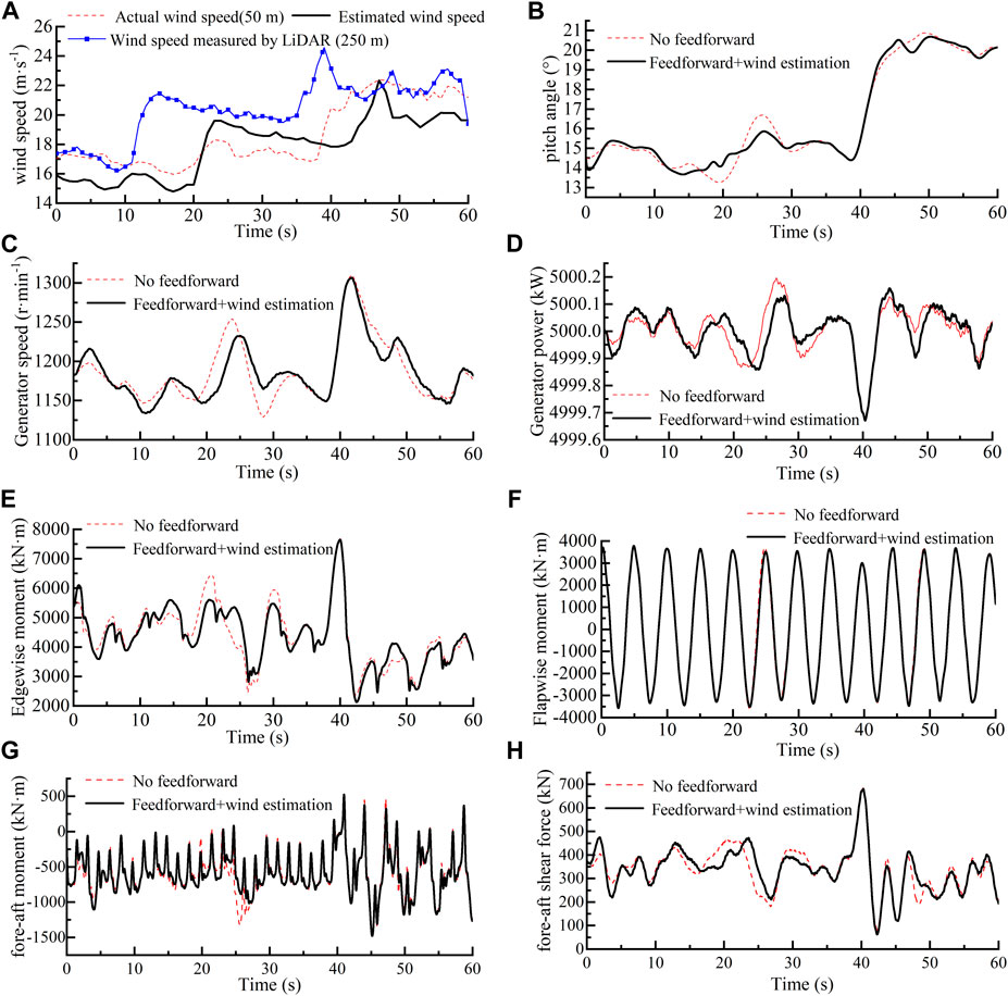
FIGURE 8. Experimental results of step wind speed.
During the process, it is found that the wind turbine operation process had a great influence on the wind speed measurement at 50 m in front of the wind turbine rotor for the rotor movement. As shown in Figure 8A, at the moment of the wind step, the measurement trend of LiDAR measuring in 250 m is consistent with 50 m, but the degree of attenuation is significantly different. On the one hand, the closer the wind speed point of the LiDAR measurement to the rotor plane, the greater the error. On the other hand, the control action of the wind turbine after the gust reaches the rotor plane affects the wind speed movement and attenuation form in front of the wind turbine rotor.
In the same day, this paper selects a period of continuously varying wind speeds with a better estimated trend. Since it is hard to directly obtain the rotor plane wind speed, the wind speed at a distance of 50 m upstream is considered the rotor plane actual speed. Furthermore, we used the wind speed of 250 m upstream to estimate the 50 m position wind speed at the same time. As shown in Figure 9A, at approximately 20 s, the wind speed measured by LiDAR at 250 m is inconsistent with the wind speed trend at 50 m, that is, the estimated wind speed curve is inconsistent with the actual wind speed curve trend of 50 m. It results in the incremental feedforward control misoperation. Moreover, it causes the rotational speed, power, and load in the incremental feedforward control have a greater fluctuation and peak than that in the non-incremental feedforward controller. Before 10 s and after 25 s, the trend of the estimated wind speed is consistent with the actual wind speed. It can be observed in Figure 9 that the generator speed fluctuation is reduced by 1.86%, the generator power fluctuation by 18.5%, the edge-wise moment fluctuation by 2.02%, and the fore-aft shear force fluctuation by 11.13%. The estimated wind speed of approximately 30 s is relatively close to the actual wind speed, so when the feedforward is active, the generator speed amplitude is reduced by 12.11 r/min, the generator power amplitude by 0.054 kW, the edge-wise moment amplitude by 417.85 kN·m, and the fore-aft shear force amplitude by 71.13 kN.
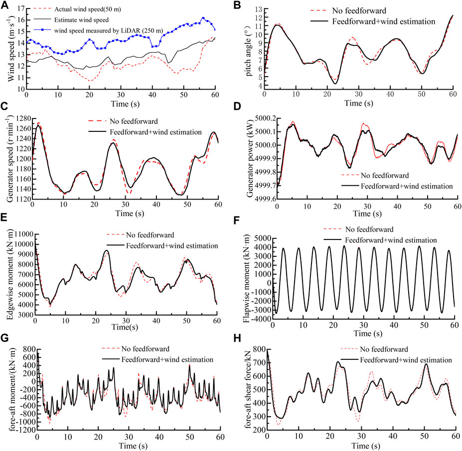
FIGURE 9. Experimental results of continuously varying wind speed.
From the above hardware-in-the-loop experiment, it can be seen that the incremental feedforward collective pitch controller based on LiDAR proposed in this paper can reduce the fluctuation range of the generator speed, power, and load. The precondition for the controller to play a role is that the estimated effective wind speed of the rotor plane should conform to the actual wind speed, and the specific values that complete consistency are not required; however, the trend should be consistent. This makes the specific requirements for wind speed estimation.
5 Conclusion
This paper derives the incremental feedforward collective pitch controller, which is superimposed on the baseline collective pitch controller to offset the impact of wind speed changes on the wind turbine. The joint simulation model of the FAST/Simulink 5-MW wind turbine is designed and established, and the incremental feedforward controller is simulated and verified under the input conditions of step wind and gust. The simulation results show that it can effectively reduce the unit load when the controller is with a limit range of 0.075 rad. For example, the load fluctuation range of gust conditions can be reduced by approximately 50%. The hardware-in-the-loop experiment results show that the incremental feedforward controller can achieve load reduction when the trend of the estimated wind speed is the same as the actual wind speed with no delay. The incremental feedforward controller is a pitch angle increment calculated by predicting wind disturbances, so it can be added as a module to the traditional collective pitch controller to reduce the system load. The modularity is suitable for commercial applications.
Data availability statement
The raw data supporting the conclusion of this article will be made available by the authors, without undue reservation.
Author contributions
QW: writing–original draft, methodology, and validation. ZD: writing–review and editing, data curation, and investigation. WC: funding acquisition, resources, writing–review and editing, methodology, project administration, and writing–original draft. JZ: writing–review and editing, investigation, software, and validation. YL: resources, writing–review and editing and project administration. HL: writing–review and editing, project administration, and validation.
Funding
The author(s) declare financial support was received for the research, authorship, and/or publication of this article. This work was supported by the National Natural Science Foundation of China (U22A20178, 52205071), the Open Foundation of the State Key Laboratory of Fluid Power and Mechatronic Systems (GZKF-202110), the Hebei Science Foundation for Distinguished Young Scholars under grant number (E2021203020), the Central Government Guided Local Scientific and Technological Development Special Fund Project (ZYYD 2022C09), the Zhejiang Province Basic Public Welfare Research Program under grant number (LHZ21E090004).
Conflict of interest
The authors declare that the research was conducted in the absence of any commercial or financial relationships that could be construed as a potential conflict of interest.
Publisher’s note
All claims expressed in this article are solely those of the authors and do not necessarily represent those of their affiliated organizations, or those of the publisher, the editors, and the reviewers. Any product that may be evaluated in this article, or claim that may be made by its manufacturer, is not guaranteed or endorsed by the publisher.
References
Bao, J., and Yue, H. Design and assessment of a LIDAR-based model predictive wind turbine control[J]. Energies, 2022, 15(17): 6429, doi:10.3390/en15176429
Bao, J., Yue, H., Leithead, W. E. L., and Wang, J. Q. Feedforward control for wind turbine load reduction with pseudo-LiDAR measurement[J]. Int. J. Automation Comput., 2018, 15 (2): 142–155. doi:10.1007/s11633-017-1103-x
Bottasso, C. L., Pizzinelli, P., Riboldi, C. E. D., and Tasca, L. (2014). LiDAR-enabled model predictive control of wind turbines with real-time capabilities[J]. Renew. Energy, 2014, 71: 442–452. doi:10.1016/j.renene.2014.05.041
David, S., and Steffen, R. (2016). Turbulent extreme event simulations for LiDAR-assisted wind turbine control[C]//journal of physics. Bristol: Conference Series.
Dunne, F., and Pao, L. Y. (2016). Optimal blade pitch control with realistic preview wind measurements. J. Wind Energy 19 (12), 2153–2169. doi:10.1002/we.1973
Haizmann, F., Schlipf, D., Raach, S., et al. (2015). Optimization of a feed-forward controller using a CW- LiDAR system on the CART3[C]//American Control Conference. Chicago.IEEE,
Han, B., Zhou, L., and Zhang, Z. (2018a). LiDAR-assisted radial basis function neural network optimization for wind turbines. IEEJ Trans. Electr. Electron. Eng. 13 (2), 195–200. doi:10.1002/tee.22514
Han, B., Zhou, L., and Zhang, Z. LIDAR-assisted radial basis function neural network optimization for wind turbines[J]. IEEJ Trans. Electr. Electron. Eng., 2018b, 13(2): 195–200. doi:10.1002/tee.22514
Jia, C., Wang, L., Meng, E., Chen, L., Liu, Y., Jia, W., et al. Combining LIDAR and LADRC for intelligent pitch control of wind turbines[J]. Renew. Energy, 2021, 169: 1091–1105. doi:10.1016/j.renene.2021.01.065
Jonkman, J., Butterfield, S., Musial, W., et al. (2009a). Definition of a 5 MW reference wind turbine for offshore system development[R]. Golden, CO (United States). USA, National Renewable Energy Lab NREL.
Jonkman, J., Butterfield, S., Musial, W., et al. (2009b). Definition of a 5 MW reference wind turbine for offshore system development[R]. Golden, CO (United States): National Renewable Energy Lab NREL.
Khaniki, M. S., Schlipf, D., and Cheng, P. (2018). A comparison between LIDAR-based feedforward and DAC for control of wind turbines[C]//IEEE Conference on Control Technology and Applications (CCTA). Copenhagen, Denmark: CCTA.
Mathur, R. R., Rice, J. A., Swift, A., and Chapman, J. (2017). Economic analysis of LiDAR-based proactively controlled wind turbines. Renew. Energy 103, 156–170. doi:10.1016/j.renene.2016.10.069
Mikkelsen, T. (2014). Wind turbine improvements by wind-LiDAR-based preview and control. Wash. Dep. Wind Energy Annu. Rep. 2013, 18.
Schlipf, D. (2015). LiDAR Assisted control concepts for wind turbines[D]. Stuttgart: University of Stuttgart.
Schlipf, D., Fleming, P., Haizmann, F., et al. (2015). Field testing of feedforward collective pitch control on the CART2 using a nacelle-based LiDAR scanner[C]//Journal of Physics. Bristol, England: Conference Series.
Scholbrock, A., Fleming, P., Schlipf, D., et al. (2016). LiDAR-enhanced wind turbine control: past, present, and future[C]//American Control Conference. Boston.
Van, T. L., Nguyen, T. H., and Lee, D. C. Advanced pitch angle control based on fuzzy logic for variable-speed wind turbine systems[J]. IEEE Trans. Energy Convers., 2015, 30(2): 578–587. doi:10.1109/tec.2014.2379293
Yamaguchi, A., Yousefi, I., and Ishihara, T. (2020). Reduction in the fluctuating load on wind turbines by using a combined nacelle acceleration feedback and LiDAR-based feedforward control. Energies 13 (17), 4558. doi:10.3390/en13174558
Yuan, Y., Chen, X., and Tang, J. (2020). Multivariable robust blade pitch control design to reject periodic loads on wind turbines. Renew. Energy 146, 329–341. doi:10.1016/j.renene.2019.06.136
Zhang, B. J., Lin, Y. G., Chen, W. T., et al. (2021). A novel rotor effective wind speed estimation method for LiDAR application: an experimental case study. Proceedings of the Institution of Civil Engineers-Energy, 1–41.
Keywords: wind turbine, Light Detection and Ranging, collective pitch control, incremental feedforward control, predictive control, joint simulation, hardware-in-the-loop experiment
Citation: Wang Q, Du Z, Chen W, Zhang J, Lin Y and Liu H (2023) Incremental feedforward collective pitch control method for wind turbines. Front. Energy Res. 11:1326248. doi: 10.3389/fenrg.2023.1326248
Received: 23 October 2023; Accepted: 20 November 2023;
Published: 29 December 2023.
Edited by:
Xun Shen, Osaka University, JapanReviewed by:
Alan Wai Hou Lio, Technical University of Denmark, DenmarkXue Jiang, Zhejiang University, China
Copyright © 2023 Wang, Du, Chen, Zhang, Lin and Liu. This is an open-access article distributed under the terms of the Creative Commons Attribution License (CC BY). The use, distribution or reproduction in other forums is permitted, provided the original author(s) and the copyright owner(s) are credited and that the original publication in this journal is cited, in accordance with accepted academic practice. No use, distribution or reproduction is permitted which does not comply with these terms.
*Correspondence: Wenting Chen, d2VudF9jaGVuQHlzdS5lZHUuY24=