 Wei Zhang1,2
 Yong-Qiang Feng
95% of researchers rate our articles as excellent or good
Learn more about the work of our research integrity team to safeguard the quality of each article we publish.
Find out more
ORIGINAL RESEARCH article
Front. Energy Res. , 18 January 2024
Sec. Nuclear Energy
Volume 11 - 2023 | https://doi.org/10.3389/fenrg.2023.1323187
Introduction: Ice plugs acts as isolate maintenance sections during pipeline repairs in nuclear power plants can effectively reduce maintenance costs, which is formed by the cooling of liquid nitrogen. The single-jacket freezing method takes a long time for the formation of ice plugs with a certain load-bearing capacity, increasing the liquid nitrogen consumption.
Methods: In this study, a multiple-jacket method for the formation of ice plugs was proposed, and the numerical simulation using CFD (Computational Fluid Dynamics) was conducted. The effects of total jacket length and jacket number on freezing time and the consumption of liquid nitrogen were analyzed.
Results and Discussion: Research indicated that the multiple-jacket method obtained a 11%∼15% decrease in freezing time and a 18%∼26% decrease in liquid nitrogen consumption than the single-jacket method. For the multiple-jacket method, the gap between the jackets presented a certain influence on the freezing time and liquid nitrogen consumption. As the gap between the jackets increases, there exist a small increase in the freezing time, but the liquid nitrogen consumption will be reduced by 2% to 5%.
With the progress of science and technology and the needs of people’s lives, the demand for energy is rising. It is becoming crucial to search for alternative, environmentally friendly new energy sources. Nuclear energy, as an efficient and clean energy source, has become an important direction for the future development of power companies. However, the use of nuclear energy can also be dangerous and the best way to avoid this is to keep the equipment running safely and stably. Regular inspection and maintenance of equipment is therefore a fundamental requirement. During maintenance, pipelines upstream and downstream of the maintenance section need to be isolated in order to carry out equipment replacement and maintenance. However, as no valves in the vicinity of the maintenance section, isolation becomes a problem. The ice plug isolation technique has come into the picture as a solution to this problem.
Ice plug isolation technology was firstly used in the oil and gas sector as a way of locating leaks in pipelines for detection (Howard et al., 1983). It was then widely used for pipeline modifications, repairs and isolation of leaking sections (Delong et al., 1989). The main method is using refrigerant to locally cool the upstream of the maintenance section, so that the liquid in the pipeline freezes and forms an ice plug with a certain load-bearing capacity (Wang, 2006). This method enables maintenance and servicing to be carried out without downtime, significantly reducing maintenance costs. At the same time, its simple method of operation, high safety and economy enhance the maintenance capacity of the plant (Carnus and Detraz, 2014). Currently, it is used in various power generation areas, such as nuclear and thermal power. Lannoy and Flaix (1985) conducted seven liquid nitrogen freezing tests on nuclear power plant piping, through which the rate of temperature drop and thermal gradient were analyzed. The tests showed that ice plugs can withstand very high pressures and can be used in the nuclear power sector. Ning and Chen (2015) presented six application stages and application risks of using ice plug technology in power plants, and suggested how to deal with ice plug failure. Xu et al. (2015) analyzed the method of detecting ice plug formation when used in the nuclear power industry, and proposed that the technology has great prospects for application in nuclear power. Du and Xie (2018) analyzed the precautions to be taken in the practical application of the ice plug technology with the example of overhauling a 600 MW thermal power unit. Similarly, the technology has a long and extensive history of application in small diameter pipelines (Liang et al., 2010; Lv and Zhao, 2017). As early as 1977, DN100 pipes were successfully plugged (Zhao and Zhang, 1985). In addition, the technology has also been used in nanoscale pipes (Gui and Liu, 2004).
The temperature of the pipe wall and the size of the pipe diameter are important conditions affecting the formation of ice plugs. It was found that the initial temperature of the liquid in the pipe and the flow rate of the liquid had an important influence on the formation of ice plugs (Kitanin É et al., 2016). Bowen et al. (1990) studied the freezing of ice plugs in vertical pipes from 100 mm to 250 mm at different initial liquid temperatures. As the water temperature approached 0°C, the freezing time tended to be more proportional to the cross-sectional area of the pipe. The freezing time becomes longer with the increasing initial water temperature. Keary and Bowen (1998) found in their numerical calculations that complex temperature changes in the pipe wall can produce natural convection at pipe diameters less than 100 mm, which affects the formation of ice plugs. In addition, the formation of ice plugs at an initial temperature satisfies the formation of ice plugs causes the local cross-sectional area to decrease, resulting in an increasing in flow velocity. Excessive fluid velocities can scour the ice surface and affect the formation of ice plugs (Maintenance Division and Qin Shan Third Nuclear Power Co, 2003). On the other hand, the flow velocity in the pipe affects the temperature difference between the pipe wall and the fluid, which indirectly affects the freezing time. It has been found that higher flow rates tend to require lower pipe wall temperatures to form ice plugs Jain et al. (2018), Bak et al. (2001) conducted a series of tests using a 600-mm-long, 168-mm-diameter jacket. The results showed that when the fluid in the pipe was at rest, the ice plug finally closed radially not at the center of the pipe, but about 50 mm from the center of the pipe due to natural convection; when the flow rate of the fluid in the pipe was 0.0025 m3/min, the closing point was 20 mm from the center of the pipe. Liu (2019) found that it is feasible to perform ice plugging in a flowing pipe, but there is a maximum limit to the flow rate for different pipe diameters and the maximum value is related to the pipe diameter. When dry ice was used to freeze the pipes, the upper flow limits for ice plug formation in DN50, DN80 and DN100 pipes were between 200 and 205 mL/min, 300–310 mL/min and 342–350 mL/min, respectively. In addition, the ice plug formed needs to have a certain pressure-bearing capacity. Martin et al. (2004) found that ice plugs were able to withstand pressures of at least 10 bar in a series of experiments with polymer pipes of different sizes. It was found that the adhesion strength of ice to stainless steel increases linearly with decreasing temperature (Jellinek, 1959). After freezing temperatures below −20°C, the ice-substrate interface stabilizes and the ice adhesion strength remains almost constant (Dong et al., 2014).
However, due to the expansion of the ice and the cold contraction of the pipe during freezing, the pressure-bearing capacity of the ice plug depends on more than just the adhesion strength. Different pipe diameters and ice plug lengths have an influence on the load-bearing capacity of the ice plug. Fang and Li (2009) summarized the relationship between different liquid media and ice plug length to diameter ratio. For a DN100 pipe, the internal medium is heavy oil, the pressure is 1.06 MPa, and considering a 50% safety factor, the ice plug length needs to be 375 mm. For the freezing of a large diameter long pipe, it requires a large amount of refrigerant and a long freezing time (Liu, 2012). In the experiments with different freezing lengths, Takefuja and Okubo (2018) found that the double ice plug freezing method provided better performance. Experiments have shown that the double ice plug freezing method can increase the pressure carrying capacity by four times compared to the single ice plug freezing method, while reducing refrigerant consumption. Xie et al. (2020) found that the vicinity of the jacketed liquid nitrogen inlet creates a greater temperature gradient in the pipe wall and that the refrigerant inlet should be placed in the variable pressure section of the pipe in order to reduce the pressure on the pipe. Burton (Burton, 1986) studied the formation of ice plugs in a DN100 vertical pipe and found that the neck of the ice plug sloped downward under the influence of gravity at the beginning of the experiment and grew upward after completely blocking the pipe. Richardson et al. (2003) found that there is a limit to the size of circular pipes that can be plugged using the ice plug technique. By using non-circular cross-section pipes were able to speed up the freezing time. Experiments showed that the freezing time for non-circular cross-sections was significantly shorter than for 50 or 35 mm round pipes. Stone et al. (2004) performed finite element modeling of non-circular cross-section pipes and their results showed that the freezing time predicted by the simulations could be well equated with the experimental freezing time for a range of conditions. It was noted that the thermal resistance of the pipe in forming ice plugs depends mainly on the minor axis length, so for large diameters, high temperature environments, etc., ice plugs may not form. Corbescu et al. (2021) simulated the freezing of a 200 mm pipe diameter water-containing pipe at 15°C by means of FLUENT simulation. Their model of VOF (Volume of Fluid) multiphase flow was used, simulated using the energy equation and the melting and solidification model and simultaneously set up the same experiment for verification. It was found that there is a time difference of about 28% between the simulated and experimental ice plug formation, which is caused by two factors: the experiment requires extra time to fill the freezing unit with liquid nitrogen; and the CFD model ignores the heat loss from the freezing unit and the outer pipe wall.
As can be seen from the above literature, the formation and pressure-bearing capacity of ice plug isolation technology has been studied worldwide. However, a large number of its studies have used the single jacketed form. The only literature (Takefuja and Okubo, 2018) that uses multiple jackets does not provide a comparative analysis of the application scenarios under different circumstances. This paper aims to investigate the effects of the number of jackets, total jacket length and jacket gap on freezing time and liquid nitrogen consumption by means of numerical simulations. Theoretical support is provided for practical plant applications.
ANSYS Workbench platform integrates geometric modeling, meshing, fluid, thermal analysis, thermos-solid coupling analysis and post-processing modules into one, which realizes accurate transfer of simulation information between different modules, therefore, this paper is based on ANSYS platform for numerical simulation work.
The pipe is considered as an axisymmetric rotating body without considering the presence of fixed structures on the pipe, etc. The temperature loaded on the pipe is treated as axisymmetric loading and the temperature varies along the axial direction. With the above assumptions, the test can be simplified to a spatial axisymmetric problem. The problem is actually a two-dimensional problem, and simplifying the three-dimensional to two-dimensional can significantly reduce the calculation time. Therefore, this paper simplifies the ice plugging problem to model and simulate the 1/2 pipe with the pipe axis as the boundary line. At the same time, considering that the focus of this paper is on the time of ice plug formation, the wall thickness is ignored.
In summary, this paper takes a cast iron pipe with a diameter of 130 mm and a length of 2,000 mm as the research object, and uses ANSYS for CFD simulation and selects 1/2 profile for modeling. The geometric model is shown in Figure 1. Where the A1 surface is water or ice inside the pipe, and the A2 surface is the pipe wall. Neglecting the pipe wall thickness, the temperature loads are loaded at the lower edge of the A2 surface according to the actual distribution.

FIGURE 1. Two-dimensional geometric model of the pipe.
As described in the previous subsection, a two-dimensional model is used in this paper to simulate the actual pipeline situation using an axisymmetric approach. Since the two-dimensional surface of the pipe is a regular plane, a smaller structured mesh is used to partition the fluid region with high solution accuracy. In order to make the model better reflect the computational situation, the mesh is divided using all quadrilaterals. Figure 2 shows the division of the mesh.
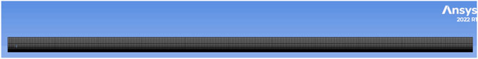
FIGURE 2. The division of the mesh.
In order to eliminate the influence of the divided grid size and the set step size on the calculation results, the grid independence and step independence need to be verified. To avoid the influence of the sparsity degree on the experimental results, five numerical simulations with different mesh quantities were performed on the axial surface under the same conditions. Since the focus of this paper is on the time of ice plug formation, the calculation results are indexed by the freezing time variation. The working conditions under five different grid quantities are given in Table 1, including the distribution of pipe wall temperature load, pipe length, pipe diameter length, and total jacket length.
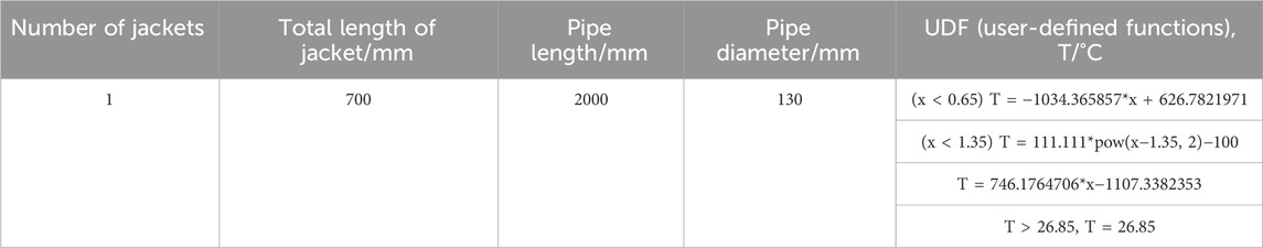
TABLE 1. Working conditions with different mesh division.
For the axial surface, the longitudinal mesh is selected to be divided into five groups of 25 mesh numbers, and the axial mesh numbers are set to 200, 250, 300, 350 and 400 mesh numbers for the same numerical calculations, and the results of the calculations are shown in Figure 3. Taking the numerical simulation results with 200 grid numbers as the comparison standard, the relative errors generated by the freezing time in the other four grid cases are −1.3%, 1.4%, 2.8%, and 2.8%, respectively. It can be seen that the relative errors of all five grids are less than 3%, which indicates the validity of the simulation. To ensure the efficient and accurate calculation, the number of 300 meshes is selected for axial division. In order to better show the effect of temperature load on the lower surface, the boundary layer is divided at the lower surface. The boundary layer is added to the longitudinal mesh in a deviated manner. To avoid the influence of the sparsity of the longitudinal mesh on the experimental results, the division of the longitudinal mesh was numerically simulated under the same conditions.
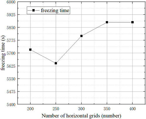
FIGURE 3. Verification of horizontal grid irrelevance.
The working condition is the same as that of the axial grid, and the axial grid is selected to be divided into five groups of 300 meshes, and the longitudinal grid is set to be 15, 20, 25, 30, and 35 meshes for numerical calculations, and the results of the calculations are shown in Figure 4. Taking the numerical simulation results with 15 grid numbers as the comparison standard, the relative errors generated by the freezing time for the other four grid cases are −2.4%, −1.4%, −0.3% and −2.4%, respectively. It can be seen that the relative errors of all five grids are less than 3%, which indicates the validity of the simulation. To ensure the efficient and accurate calculation, the number of longitudinal division 25 grids is chosen.
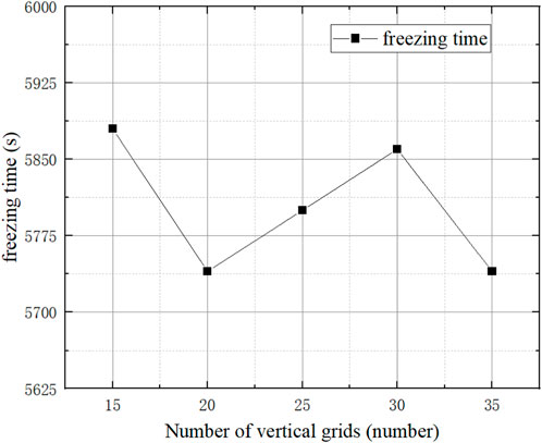
FIGURE 4. Verification of vertical grid independence.
The freezing process of the ice plug has a phase change process of water and ice. Therefore, the accurate definition of the physical parameters of ice and water becomes the focus of the numerical simulation process. The physical parameters of water can be called and selected by refprop software, and the selected physical parameters are shown in Table 2. In contrast, the physical parameters of ice are relatively difficult to find. In some literature (Corbescui et al., 2021; Seyed et al., 2023), the physical parameters of ice at some temperatures are given, and after comparison and selection with the book (Zhang and Zhao, 1987), the selected physical parameters are shown in Table 2.
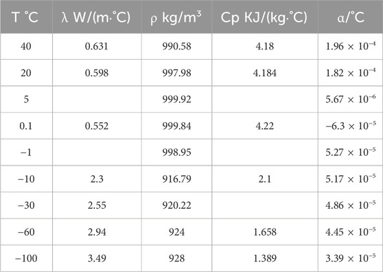
TABLE 2. The physical parameters of water/ice.
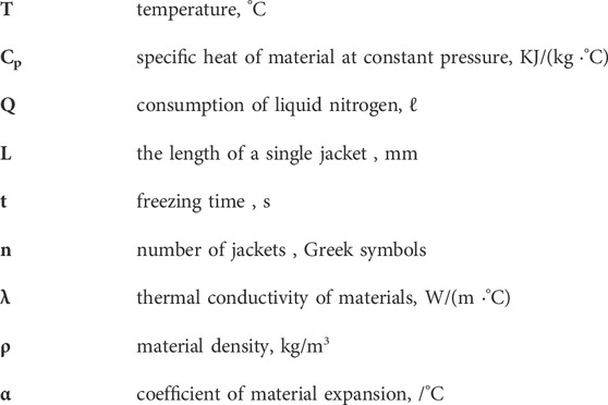
where T denotes the temperature, λ is the thermal conductivity of the material, ρ is the density, Cp is the constant pressure specific heat capacity, and α is the coefficient of expansion.
Models: Turn on the energy model; Select laminar flow for the turbulence model; Turn on the solidification and melting model.
The formation of ice plug in the pipe is mainly related to the temperature change of the pipe wall, and there is no change in its import and export. In fluent, the inlet boundary conditions are usually set as follows: pressure inlet, velocity inlet, mass flow inlet, etc. The outlet boundary conditions are usually set as follows: pressure outlet, velocity outlet, mass flow outlet, etc. This model assumes that the water in the pipe does not flow, so the inlet selects the velocity inlet, and the outlet selects the pressure outlet. The pipe wall material is selected from all the steels in the fluent database, and the pipe wall temperature is loaded using the UDF program. The complete UDF example program is shown in Figure 5, and the UDF for different jacket form examples of the same jacket total length is shown in Table 3.
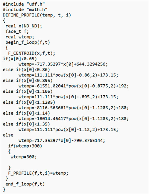
FIGURE 5. Example of pipe wall temperature distribution.
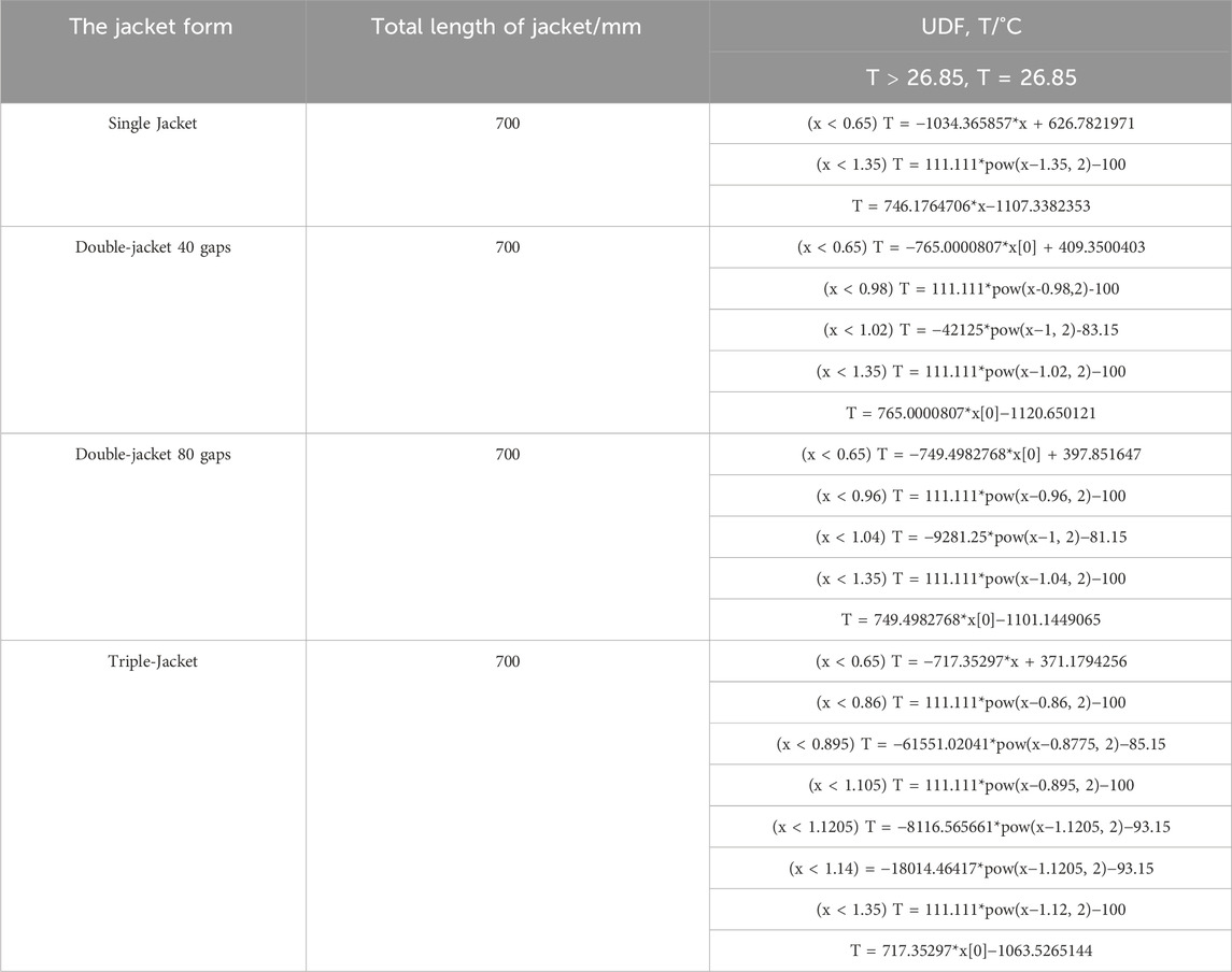
TABLE 3. UDF for different jacket cases.
Since liquid nitrogen diffuses inside the jacket in different forms in different ways and at different rates along the axial direction, a consistent diffusion of liquid nitrogen inside the jacket was used in all of the present numerical simulations. In several literatures (Wang, 2006; Corbescui et al., 2021; Shen, 2021), the temperature distribution of the pipe wall is usually derived experimentally and loaded onto the pipe surface by fitting the pipe temperature distribution at different times with different load steps. In order to simplify the calculations, the wall temperature was chosen to remain a constant low temperature at all times. Figure 6 demonstrates the temperature change of each temperature measurement point in the upper, middle and lower 15 during the preliminary test. The overall trend of each layer, as can be seen from the figure, is close to a parabolic form, with the lowest temperature at the point closest to the point of direct liquid nitrogen injection. Therefore, this diffusion approach is translated into a temperature distribution loaded on the corresponding positions of the model by an empirical formula for preliminary experiments. This empirical formula is not universal and is only used as a control for wall temperature conditions for different numbers of jackets in this paper.
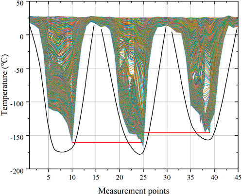
FIGURE 6. Temperature profiles for preliminary experimentation.
For the setting of liquid nitrogen inlets in different quantities and with different gaps, it is stated in the literature 26 that the liquid nitrogen inlet should be placed at the pressure change of the pipeline. Considering this point, the liquid nitrogen inlets in this paper are all set at the jacket gap, and for single jacket, the liquid nitrogen inlet is set at the back side of the jacket.
For the different number of jackets and different gaps, in order to ensure that the position of each group of jackets is basically the same, in this paper, we choose to distribute all the jackets symmetrically in the center of the pipe. That is, the center of the total length of the jacket coincides with the center of the pipe, and then symmetrically distribute the jacket.
The empirical equation for the diffusion of liquid nitrogen in the jacket is used to determine the temperature distribution of the tube wall inside the plus jacket for different situations. In combination with the empirical equation for temperature diffusion in the tube wall, the temperature load on the tube wall is set accordingly. The temperature loads for some of these cases are shown in Figure 5. In order to better monitor the effect of different conditions on the freezing characteristics of the ice plugs, the calculations in this paper use a single jacket 66% closed. Since the pipe diameters are the same, the pressure-bearing capacity of the ice plug depends mainly on the length of the complete ice plug formed. This monitoring method allows the jackets to reach an identical pressure-bearing capacity under different conditions.
Figures 7, 8 show the results of temperature and icing field calculations for different numbers of jackets when the total jacket length is 600 mm, respectively. As can be seen in Figure 7, at 66% of the jacket closure length, there is a higher temperature part (red part in the figure) in both double-jacket and triple-jacket, which occurs at the gap. This can also be seen in Figure 8, where lighter colored pits appear in both (b) and (c). The presence of this phenomenon indicates that the presence of the gap affects the overall complete molding of the ice plug, but due to its central position in the whole pipe, the volume expansion of the liquid during freezing instead increases the pressure-bearing capacity of the ice plug. In addition, in both figures, it can be found that at a total jacket length of 600 mm, the use of a single jacket is not only more time-consuming than the use of a larger number of jackets, but also less effective in closure, which indicates that the use of a single jacket at this time is not appropriate.
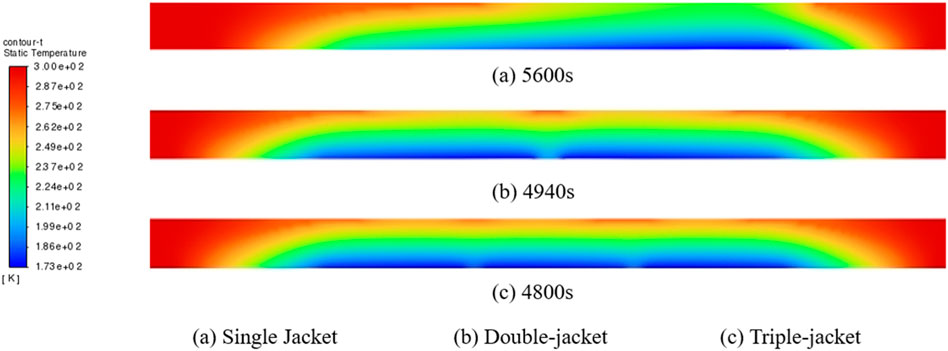
FIGURE 7. Temperature field with different number of jackets in the total jacket length of 600 mm. (A) Single jacket (5,600s), (B) double-jacket (4,940s), (C) triple-jacket (4,800s).
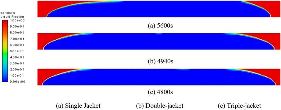
FIGURE 8. Icing field with different number of jackets in the total jacket length of 600 mm. (A) Single jacket (5,600s), (B) double-jacket (4,940s), (C) triple-jacket (4,800s).
Figure 9 shows the trend of freeze time reduction of double and triple-jacket as compared to single jacket with respect to the total length of the jacket. It can be seen from the figure that the percentage of freeze time reduction for both double and triple-jacket increases as the total length of the jacket increases. This also indicates that the use of a single jacket is no longer appropriate for jacket lengths greater than 600 mm. At a total jacket length of 1,000 mm, the use of multiple jackets already reduces the freezing time by 21.88%. In addition, it can be seen from the graph that the triple-jacket is able to shorten the freezing time more than the double-jacket, but the difference between the two is decreasing, especially at 1,000 mm, where the two are almost the same, which is partly due to the poor effect of the single jacket, which makes the denominator too large, and partly due to the influence of the liquid nitrogen inlet and the distribution of the gaps in the triple-jacket.
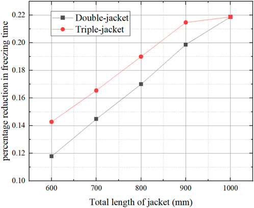
FIGURE 9. Trend in the percentage reduction in freezing time for different number of jackets.
Figure 10 and Figure 11 show the results of temperature and icing field calculations when different gaps are used in the double-jacket when the total jacket length is 600 mm, respectively. Combining the two figures, it can be seen that when the monitoring method is the same, the difference in the gap only affects the length of the unfrozen water portion at the gap, and the freezing time only changes by 0.81%.
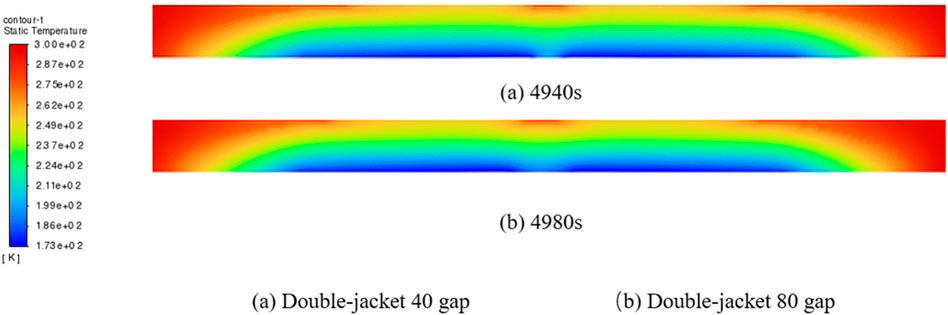
FIGURE 10. Temperature field for different jacket gaps for the total length of the 600 mm jacket. (A) Double-jacket 40 gap (4,940s), (B) Double-jacket 80 gap (4,980s).
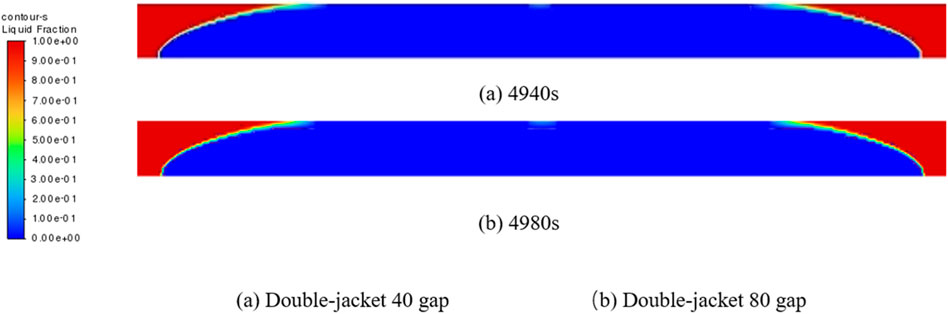
FIGURE 11. Ice field for different jacket gaps for the total length of the 600 mm jacket. (A) Double-jacket 40 gap (4,940s), (B) Double-jacket 80 gap (4,980s).
Figure 12 shows the trend of freezing time for double-jacket with different gaps at different overall jacket lengths. It can be seen from the figure that as the total length of the jacket increases, the freezing time increases for both gaps, but to a lesser extent. This increase can be regarded as the change brought about by the increase in the required freezing length with the increase in the total jacket length. In addition, comparing the two gaps, it can be seen that the trends are similar and the differences are the same. This is partly due to the fact that the trend of the effect of the different gaps on the overall freezing time is a similar one with the total length of the jacket, and partly due to the fact that the selection time step is larger, resulting in less obvious details.
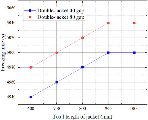
FIGURE 12. Trend of freezing time for different jacket gaps.
Figure 13 illustrates the variation of freezing time for a single jacket as the total length of the jacket varies. From the figure, it can be seen that the trend of freezing time variation of single jacket with increasing total jacket length is a linear variation. The average change value is 2 s/mm. Except, in conjunction with the graphs of single jacket icing field calculations for different total jacket lengths shown in Figure 14, it can be seen that an increasing number of pipes fail to achieve 50% closure at the unfrozen 34% jacket length. This phenomenon further indicates that when the total jacket length is long, it is more difficult to meet the actual needs of the single jacket. The equation for single jacket freezing time versus total jacket length is shown below: Figure 13 illustrates the variation of freezing time for a single jacket as the total length of the jacket varies. From the figure, it can be seen that the trend of freezing time variation of single jacket with increasing total jacket length is a linear variation. The average change value is 2 s/mm. Except, in conjunction with the graphs of single jacket icing field calculations for different total jacket lengths shown in Figure 14, it can be seen that an increasing number of pipes fail to achieve 50% closure at the unfrozen 34% jacket length. This phenomenon further indicates that when the total jacket length is long, it is more difficult to meet the actual needs of the single jacket. The equation for single jacket freezing time versus total jacket length is shown in Eq. (1):
versus total jacket length is shown below:
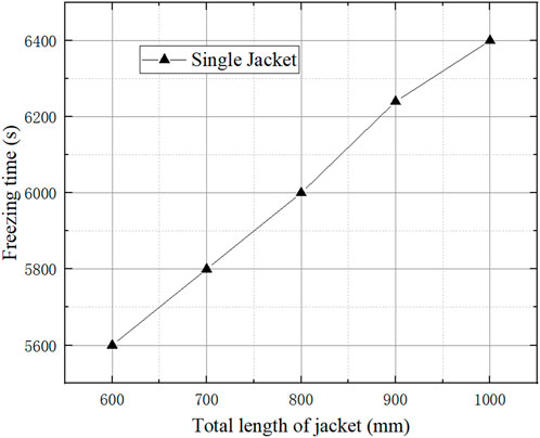
FIGURE 13. Trend of freezing time for different total jacket lengths in a single jacket.
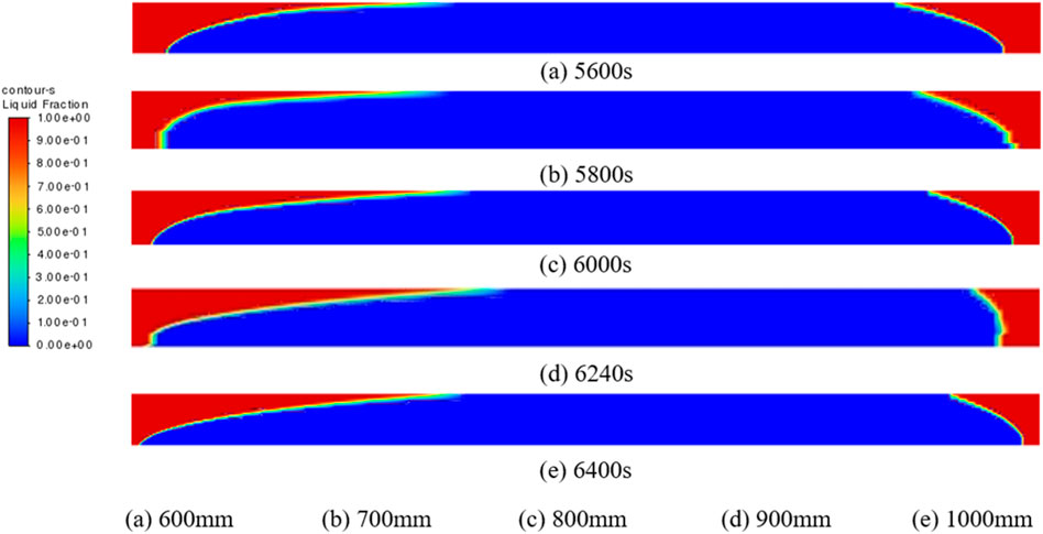
FIGURE 14. Single jacket icing field for different jacket lengths. (A) 600 mm (5,600s), (B) 700 mm (5,800s), (C) 800 mm (6,000s), (D) 900 mm (6,240s), (E) 1,000 mm (6,400s).
Figure 15 illustrates the trend in freezing time for the double-jacket 40 clearance as a function of the total jacket length. As shown, the freezing time maintains an increasing trend with increasing total jacket length, but when the total jacket length increases by 400 mm, the freezing time changes by only 60 s. This occurrence indicates that the change in total jacket length has a small effect on the freezing time for the monitoring case using 66% single jacket closure. Even though the required freezing length was increased, the enhanced freezing effect of multiple jackets resulted in a lower average wall temperature, which shortened the effect of the increase in freezing length on the freezing time.
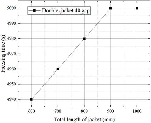
FIGURE 15. Trend of freezing time for different total jacket lengths between double-jacket 40 gap.
Figure 16 shows the trend in freezing time for the double-jacket 80 gap as a function of the total jacket length. The trend is similar to that of Figure 15, in that the freezing time tends to increase with the overall length of the jacket. Again the increase in freezing time is small, about 0.4%, with an average increase of 0.15 s/mm.
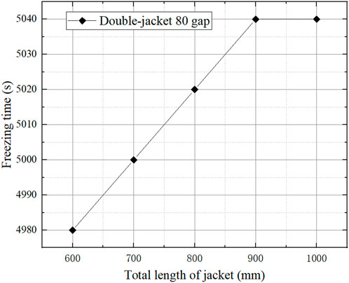
FIGURE 16. Trend of freezing time for different total jacket lengths between double-jacket 80 gap.
Figure 17 shows the results of the triple-jacket temperature field calculations for different overall jacket lengths. As can be seen from the figure, the presence of only one liquid nitrogen inlet at one gap makes the temperature distribution in the two gaps not the same. One of the gaps has a relatively low temperature distribution while the other has a relatively high temperature distribution. This situation shows that with the increase of the number of jackets, the rational arrangement of liquid nitrogen inlet distribution and gap length is a direction that needs more consideration.
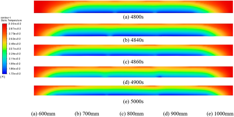
FIGURE 17. Temperature field of the total length of the triple-jackets with different jackets. (A) 600 mm (4,800s), (B) 700 mm (4,840s), (C) 800 mm (4,860s), (D) 900 mm (4,900s), (E) 1,000 mm (5,000s).
Figure 18 illustrates the trend in freezing time for triple-jacket as a function of total jacket length. Unlike the single and double-jacket, the trend in freezing time for the triple-jacket is essentially close to a quadratic curve. At lower total jacket lengths, the change in freezing time with increasing total jacket length is small, and the increase becomes more pronounced at larger total lengths. This suggests that the effect of a poor-quality gap with only one liquid nitrogen inlet on the freezing time becomes more pronounced as the total jacket length increases. As shown in the figure, when the total jacket length increases from 800 to 100 mm, the rate of change increases from 0.82% to 2.04%, which is an increase of about 2.5 times. This shows that the effect of poor quality of jacket clearance on freezing time cannot be ignored.
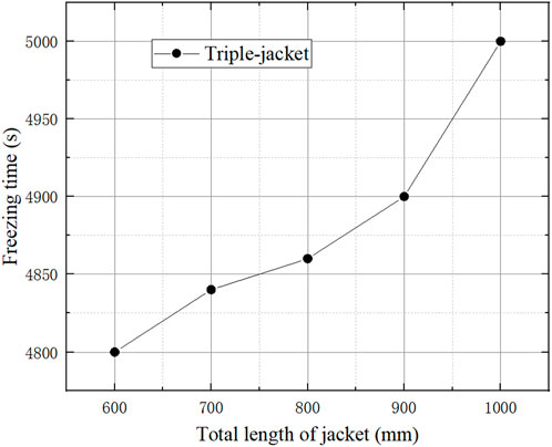
FIGURE 18. Trend of freezing time for different jacket lengths with triple-jacket.
Figure 19 shows the trend of freezing time for different number of jackets and different jacket gaps for different total jacket lengths. Overall, the freezing time in each case increases with the increase in total jacket length, which occurs due to the increase in the required freezing length, but its effect varies for different cases. For single jackets, the increase in total jacket length makes it necessary to vary while maintaining a large rate of change, while for multiple jackets the effect is smaller. This situation indicates that the freezing performance of the multiple jackets has not reached its limit at this point, while the freezing performance of the single jacket is already poor. In comparison, the double-jacket reduces the freezing time by 16.67% on average and the triple-jacket reduces the freezing time by 18.64% on average. This indicates that the freezing time can be effectively shortened by using the multi-jacket method. Compared with the double-jacket, the triple-jacket is more affected by the increase of freezing length, and the freezing time is basically the same as that of the double-jacket with 40 gaps when the total length of the jacket is increased to 1,000 mm. This suggests that for odd-numbered jackets, more consideration needs to be given to the length of the inferior gap when using them.
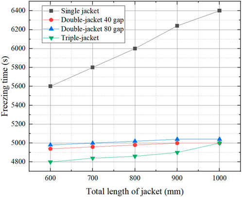
FIGURE 19. Freezing time for different jacket numbers and different jacket gaps for different total lengths of jackets.
At present, there are many factors affecting liquid nitrogen consumption, and there is no specific formula that can be used directly. Changing the internal flow path of the jacket, the injection flow rate of liquid nitrogen, and the contact method between the jacket and the pipe wall all have an effect on it. In order to compare the effect of the change in the number of jackets on the liquid nitrogen consumption, the empirical formulas are set up in this paper, combining the experimental results of double-jackets and single jackets in the literature (Takefuja and Okubo, 2018). The most important variation factor in the empirical formula is the freezing time, and all other factors are used as adjustments to the parameters under a certain jacket structure. It is worth noting that when different jacket structures and liquid nitrogen flow rates are used may make the formula no longer applicable. The specific formula is shown in Eq. (2):
where
Based on the freezing time calculations shown in Section 3.1, the liquid nitrogen consumption for different cases was calculated and the results are shown in Figure 20. From the figure, it can be seen that the liquid nitrogen consumption in all triple-jacket cases increases with the total length of the jacket, and the trend of liquid nitrogen consumption is basically proportional to the total length. The creation of this situation indicates that the increase in the required freezing length still has a more pronounced effect on the liquid nitrogen. In order for the ice plug to maintain sufficient pressure capacity, the increase in the required freezing length increases the amount of time that liquid nitrogen needs to be introduced. Except, for a given total jacket length, the liquid nitrogen consumption decreased with the increase in the number of jackets. There was an average reduction of 21.57% for double-jacket and 25.5% for triple-jacket. This shows that the use of multiple jackets is effective in reducing the liquid nitrogen consumption. This is due to the fact that the increase in the number of jackets reduces the required freezing length of each jacket, and the average temperature distribution inside the jacket is reduced, accelerating the formation of ice plugs. For double-jacket, the increase in clearance results in some increase in freezing time, but also some decrease in liquid nitrogen consumption. The average increase in freezing time is 1% and the average decrease in liquid nitrogen consumption is 3.72%. Same as the change of freezing time, the triple-jacket is more affected by the change of total jacket length, and the effect of inferior gap in the triple-jacket is still not negligible.
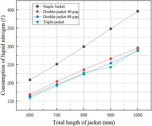
FIGURE 20. Liquid nitrogen consumption for different jacket numbers and different jacket gaps for different total lengths of jackets.
In this study, simulations based on a CFD model are carried out for a formation of ice plugs from liquid in nuclear power pipes cooled by several jackets. The effects on the freezing time of the ice plugs are analyzed and compared for the different cases. In addition, the liquid nitrogen consumption for the different cases was compared and analyzed based on the empirical formula for liquid nitrogen consumption. The following conclusions were obtained.
Compared with the single-jacket freezing method, the multi-jacket method can make the freezing time reduced by 11%–22% and the liquid nitrogen consumption reduced by 18%–26%.
In the double-jacketed model, the freezing time increased by about 1% with the increase of the jacket gap, but the liquid nitrogen consumption decreased by 2%–5%.
In the double-jacketed model, there was an increase in freezing time of about 0.4% with the increase in total jacket length. This indicates that the freezing capacity of the double-jacket is not at the limit in the experimental range of 400–1,000 mm total jacket length. Each jacket length is in the optimal range, and the average temperature distribution inside the jacket remains low, still in the optimal range of jacket use.
For the triple-jacket, the freezing time and liquid nitrogen consumption produced large fluctuations in variation when the total length of the jacket was larger. This situation arises to show that the defect of poor-quality gap in the triple-jacket will have a more obvious effect on the triple-jacket when the jacket length is longer.
The raw data supporting the conclusion of this article will be made available by the authors, without undue reservation.
WZ: Data curation, Formal Analysis, Writing–original draft. KX: Methodology, Resources, Software, Writing–original draft. M-LH: Software, Writing–review and editing. H-JL: Data curation, Formal Analysis, Validation, Writing–original draft. HC: Formal Analysis, Supervision, Writing–review and editing. L-QW: Funding acquisition, Investigation, Project administration, Writing–review and editing. Y-QF: Formal Analysis, Investigation, Supervision, Validation, Writing–review and editing.
The author(s) declare that no financial support was received for the research, authorship, and/or publication of this article.
Authors WZ, KX, and M-LH were employed by China Nuclear Power Operation Management Co., Ltd.
The remaining authors declare that the research was conducted in the absence of any commercial or financial relationships that could be construed as a potential conflict of interest.
All claims expressed in this article are solely those of the authors and do not necessarily represent those of their affiliated organizations, or those of the publisher, the editors and the reviewers. Any product that may be evaluated in this article, or claim that may be made by its manufacturer, is not guaranteed or endorsed by the publisher.
Bak, Y. D., Cho, H. C., Choi, B. I., et al. (2001). An experimental study for the liquid freezing phenomena in a pipe during ice plugging. Trans. Korean Soc. Mech. Eng. B 25 (3), 366–372.
Bowen, R. J., Burton, M. J., and Smith, G. S. (1990). The effect of pipe diameter and pressure drop on the formation of ice plugs in pipelines. Begel House Inc.
Burton, M. J. (1986). An experimental and numerical study of plug formation in vertical pipes during cryogenic pipe freezing. Southampton: University of Southampton.
Carnus, M., and Detraz, J. M. (2014). Ice plugging of piping: from the theory to the practice - 25 years feedback from EDF PWRs. EDF PWRs 2011 (1), 73–77. doi:10.1051/rgn/20111073
Corbescu, B., Puiu, D., Gyongyosi, T., et al. (2021). Computational model and experimental validation of ice plug obturation of a horizontal pipe. U.P.B. Sci. Bull. Ser. D. 83, 281–292.
Corbescui, B., Puiui, D., Matell, E., Valeriu, N. P., et al. (2021). CFD model for the heat transfer during the ice plugging process of large diameter pipes. J. Nucl. Res. Dev. (05), 49–55.
Delong, T., Patel, B., Galanti, P., et al. (1989). Freeze sealing (plugging) of piping: a guide for nuclear power plant maintenance personnel. USA: Department of Energy Office of Scientific and Technical Information.
Dong, W., Ding, J., and Zhou, Z. X. (2014). Experimental study on the ice freezing adhesive characteristics of metal surfaces. J. Aircr. 51 (3), 719–726. doi:10.2514/1.c032393
Du, J. L., and Xie, H. T. (2018). Application of ice plugging method on 600MW thermal power units. Sci. Technol. Innovation (32), 66–67.
Gui, L., and Liu, J. (2004). Ice valve for a mini/micro flow channel. J. Micromechanics Microengineering 14 (2), 242–246. doi:10.1088/0960-1317/14/2/011
Howard, G. J., Cai, B. C., and Huang, Z. G. (1983). Advances in freeze blocking technology during pipeline pressure testing. Cryog. special gas (3), 49–51.
Jain, A., Miglani, A., Huang, Y., Weibel, J. A., and Garimella, S. V. (2018). Ice formation modes during flow freezing in a small cylindrical channel. Int. J. Heat Mass Transf. 128 (JAN), 836–848. doi:10.1016/j.ijheatmasstransfer.2018.08.051
Jellinek, H. G. (1959). Adhesive properties of ice. J. Colloid Sci. 14 (3), 268–280. doi:10.1016/0095-8522(59)90051-0
Keary, A. C., and Bowen, R. J. (1998). Analytical study of the effect of natural convection on cryogenic pipe freezing. Int. J. Heat Mass Transf. 41 (10), 1129–1138. doi:10.1016/s0017-9310(97)00269-x
Kitanin É, L., Smirnov, Y. A., and Lebedev, M. E. (2016). Development of flow and heat transfer during filling a pipeline with water at the pipe wall temperature below the freezing point. J. Eng. Phys. Thermophys. 89 (4), 808–814. doi:10.1007/s10891-016-1440-6
Lannoy, A., and Flaix, B. (1985). Experimental analysis of the obturation of pipes by ice plugs. Nucl. Eng. Des. 86 (3), 305–313. doi:10.1016/0029-5493(85)90296-1
Liang, Z., Lan, H. Q., Li, L. M., and Deng, X. Local freeze plugging technology for small diameter natural gas pipelines. Nat. Gas. Ind.,2010,30(09):69–127.
Liu, Y. (2012). Theoretical study on the temperature field of pipeline during ice plug formation. Sci. Technol. Inf. (06), 242.
Liu, Y. M. (2019). Exploration of dry ice ice plugging under different flow rates and different pipe diameters working conditions. Equip. Manag. Maintenance (23), 143–145. doi:10.16621/j.cnki.issn1001-0599.2019.12.73
Lv, S. G., and Zhao, J. F. (2017). Research and application of freezing method in small diameter water supply pipe stoppage. China Water Supply Drainage 33 (16), 117–120. doi:10.19853/j.zgjsps.1000-4602.2017.16.027
Maintenance Division, Qin Shan Third Nuclear Power Co (2003). Development and application of ice plugs in the CANDU project [C]//Workshop on safe operation of nuclear power plants in Zhejiang Province. Chinese Nuclear Society.
Martin, C. I., Richardson, R. N., and Bowen, R. J. (2004). An investigation of the cryogenic freezing of water in non-metallic pipelines. Am. Inst. Phys. AIP 711 (50), 232–239.
Ning, X. F., and Chen, W. (2015). Introduction to the application of "ice plug technology" in power plants. Henan Electr. Power 156 (04), 59–60+63.
Richardson, R. N., Bowen, R. J., and Sharman, A. (2003). Accelerated pipe freezing in non-circular sections. Chem. Eng. Res. Des. 81, 467–473. doi:10.1205/026387603765173727
Seyed, S. M. A., Sébastien, P., Kurosh, S., et al. (2023). Solidification analysis in an ice-on-coil ice storage system: experimental and numerical approaches. J. Energy Storage 65, 107291.
Shen, X. (2021). Mechanical analysis and safety study of ice plugging process in nuclear power pipelines[D]. Zhejiang: Zhejiang University of Technology.
Stone, H. B., Martin, C. I., Richardson, R. N., and Bowen, R. (2004). Modelling of accelerated pipe freezing. Chem. Eng. Res. Des. 82 (10), 1353–1359. doi:10.1205/cerd.82.10.1353.46736
Takefuja, Y., and Okubo, T. (2018). Double-ice-plug freezing using liquid nitrogen for water pipe repairs. Urban Water J. 15 (1), 97–99. doi:10.1080/1573062x.2017.1395900
Wang, H. Y. (2006). Research on the application of ice plug technology in nuclear power plants. Shanghai: Shanghai Jiaotong University.
Xie, L. J., Shen, X., Lin, H. B., et al. (2020). Study of liquid nitrogen ice plug test and its stress distribution in industrial pipelines. Cryog. Eng. (06), 38–43.
Xu, C., Wang, Q. Y., Xiao, Z. Q., et al. (2015). Research and application of ice plug technology in the Fu Qing nuclear power project. Energy Environ. (04), 27–29.
Zhang, J. R., and Zhao, Y. Y. (1987). Handbook of thermophysical properties of substances commonly used in engineering [M]. Beijing: New Age Press.
Zhao, W. J., and Zhang, C. T. (1985). Cold embrittlement of pipes in freeze blocking at -196°C. Low Temp. Special Gas (02), 29–31.
Keywords: nuclear power pipelines, liquid nitrogen, ice plugs, multi-jackets, liquid nitrogen consumption
Citation: Zhang W, Xu K, Hu M-L, Liang H-J, Chen H, Wang L-Q and Feng Y-Q (2024) Numerical simulation of ice plugging process using multi-jacket method in nuclear power pipes. Front. Energy Res. 11:1323187. doi: 10.3389/fenrg.2023.1323187
Received: 17 October 2023; Accepted: 27 December 2023;
Published: 18 January 2024.
Edited by:
Xingang Zhao, Oak Ridge National Laboratory (DOE), United StatesReviewed by:
Xiaoqin Zhi, Zhejiang University, ChinaCopyright © 2024 Zhang, Xu, Hu, Liang, Chen, Wang and Feng. This is an open-access article distributed under the terms of the Creative Commons Attribution License (CC BY). The use, distribution or reproduction in other forums is permitted, provided the original author(s) and the copyright owner(s) are credited and that the original publication in this journal is cited, in accordance with accepted academic practice. No use, distribution or reproduction is permitted which does not comply with these terms.
*Correspondence: Yong-Qiang Feng, aGl0ZmVuZ3lxQGdtYWlsLmNvbQ==
Disclaimer: All claims expressed in this article are solely those of the authors and do not necessarily represent those of their affiliated organizations, or those of the publisher, the editors and the reviewers. Any product that may be evaluated in this article or claim that may be made by its manufacturer is not guaranteed or endorsed by the publisher.
Research integrity at Frontiers
Learn more about the work of our research integrity team to safeguard the quality of each article we publish.