 Efecan Demirci†
 Andrew Wojtanowicz*
- Craft and Hawkins Department of Petroleum Engineering, Louisiana State University, Baton Rouge, LA, United States
Sustained Casing Pressure (SCP) is the persistent casinghead pressure resulting from the well’s annular integrity loss and migration of gas above the leaking cement sheath. Downhole—intervention methods for SCP removal employ workover rigs to access and plug off the leaking annulus at depth from within the well. The inexpensive rig-less method of Buoyant Kill involves surface injection of immiscible heavy fluid at the casinghead into the well’s annulus to replace the annular fluid column above the gas-leaking cement and stop gas migration. Laboratory and pilot-size testing have shown feasibility of the method. Presented here, is a field-scale demonstration experiment conducted in a pressurized 2750-foot well with water displaced by an immiscible brominated organic fluid over 20-h long operation. Discussed is experimental design supported by fluid selection study, benchtop and pilot tests, and fluid transport model. Also analyzed is the process performance and operational problems. The results confirm feasibility of the Buoyant Kill technique for SCP removal. The overall change of the wellhead and downhole pressures follows the expected patterns indicating partial removal of the simulated SCP. The removal is incomplete due to pumping pressure pulses and wellhead pressure variations resulting in some emulsification of the two fluids and partial loss of the injection fluid into the overflow. The results show that wellhead pressure control and injection pump operation are critical for successful SCP removal using the Buoyant Kill technique.
Introduction
Sustained Casing Pressure (SCP) is the pressure at the top of well’s annulus that cannot be permanently bled off as it is caused by the loss of well’s integrity—gas migration in the annular fluid above the top of degraded and leaking cement sheath. Cement degradation is a time-dependent and complex process resulting from variety of physical, chemical and microbial reactions (Achang et al., 2020; Seyyedi, et al., 2020; Taleghani and Santos, 2023; Yan et al., 2023). Disintegrated cement provides flow pathways for gas escape from the cement top into the annular fluid.
If excessive, SCP may cause failure of either the casing head or casing shoe—both resulting in atmospheric gas emissions or even catastrophic well blowouts (Grace, 1994; Scot et al., 1999). The US regulations require removal of severe SCP to continue operation and removal of any SCP prior to well’s plugging and abandonment (P&A) operations.
Preventing SCP requires improvement of cement-sheath quality (Landry et al., 2015) by using specialized cementing techniques providing effective zonal isolation—such as casing expansion (Kupresan et al., 2014), casing patching (Saltel et al., 2015), use of self-healing cement (Khattak et al., 2015; Landry et al., 2015; Shadravan and Amani, 2015), or expandable cement system (Tanoto et al., 2016). Despite the new technology, most wells may still develop SCP so there is a need for advancing the SCP remediation technology.
Remediation of gas migration through annular cement channels and cracks is technically difficult. The downhole—intervention methods for SCP removal employ workover rigs to access and plug off the leaking annulus at depth from within the well. They are very expensive and not always effective. One of these techniques, drilling through inner casing for squeeze cementing has proved to be highly unreliable even after many trials (Bourgoyne et al., 2000). Another technique of milling a section of the inner casing for placing cement plug to intercept gas flow has also been more effective (Obodozie et al., 2016) but still unreliable in wells with eccentric inner casing due the unknown size of the milling tool (Milanovic and Smith, 2005). An ultimate (and very costly) technique involves cutting off and removing the upper section of the inner casing to replace the leaking cement. The technique is effective but, reportedly, can only be used in wells with no cement sheath outside the upper section of inner casing (Milanovic and Smith, 2005). The reported most effective use of the downhole-intervention method for successful SCP removal in twelve wells in the Gulf of Mexico was to employ a site-specific combination of the above techniques to stop gas migration in the affected annuli (Soter et al., 2003).
Another concept for SCP removal—the wellhead intervention method—involves injec\tion from the well’s top by accessing the casinghead to replace annular fluid above the cement top with a sealant or heavy fluid to either bridge the annulus or increase hydrostatic pressure at the cement top to stop gas migration (Horton et al., 2004). Initially, the injection was performed with a flexible tubing inserted through the casinghead’s valve down the annulus using the CARS technique (Casing Annulus Remediation System). The technique was risky as it required bleeding down the casinghead pressure (SCP) to zero to insert the flexible tubing and it also failed to lower the tubing significantly deep in the casing annulus (Wojtanowicz et al., 2001). Direct injection into the casinghead appeared to be the only option for successful wellhead intervention.
Initial technique involved injection of a low-melting-point alloy metal to settle down the annulus and melting it with an induction-heating tool to create an impermeable plug at the top of cement (Carpenter et al., 2004). However full-scale testing showed the technique limited to small innermost annuli due to the heat dissipation problem. Another technique involves step-wise squeezing an epoxy resin system into the casinghead with delayed setting time of the resin to bridge either the annulus or the cement. A successful field implementations of the technique resulted in SCP removal at the top of three annuli with unknown depths of the top cement (Wajid et al., 2022).
The wellhead intervention method was simplified with the buoyant displacement concept of injecting heavy fluid directly into the casinghead’s valve so the fluid (kill fluid, KF) would settle down by buoyancy, displace the lighter annular fluid (AF) and “kill” the pressure at the cement top as shown in Figure 1.
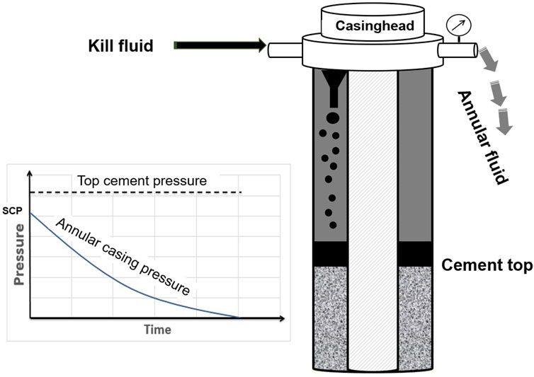
FIGURE 1. Concept of Bouyant Kill method for removal of Sustained Casing Pressure.
Initial application of buoyant displacement—named the Bleed-and-Lube (B&L) technique, was a simple and least expensive of all SCP removal methods. B&L involved replacing the fluid in the annulus (AF) with a heavier fluid (KF) by consecutive cycles of pressure removal through bleeding followed with “lubrication” (low-rate injection) of small batches of KF.
Field implementation of B&L technique using weighted drilling mud as KF showed its inability to significantly reduce SCP before wells stopped taking more fluid or even developed a secondary leak (Bourgoyne et al., 2000). Also, attempts of using Zinc Bromide as KF showed some reduction of SCP that was insufficient for to terminate gas migration. Ineffectiveness of the B&L technique was attributed to physical and chemical interaction of KF with AF: flocculation—in case of Zinc Bromide KF, and miscibility—in case of weighted mud KF, that was also demonstrated with successful immiscible buoyant settling of heavy brine or bentonite slurry in the column of white oil (Nishikawa, 1999; Nishikawa et al., 2001).
The miscibility effect in SCP buoyant kill process was further demonstrated in the visualization study using a parallel-plate “slot” physical model and showing rapid mixing of the water-based KF with AF fluids at the very top of the fluid column (Demirci and Wojtanowicz, 2016a). In contrast, hydrophobic heavy KFs were successfully able to settle to the bottom in the column of the (hydrophilic) clay-water suspensions simulating water-base annular fluid.
The bench-top size visualization experiments with the “slot” physical model provided useful observation of the buoyant slippage and lack of mixing in the stagnant column of annular fluid. They also showed advantage of brominated organics as potential KFs. However, they could not show the effect of gas migration during the KF settling process. Moreover, small size (three-foot high) of the physical model did not replicate the steady-state process of downward settling (Demirci and Wojtanowicz, 2016a).
Formulation of KF designated for the field-size process required research into the chemistry of such fluids and their physical interaction with the AF during the KF settling process. Heavy and highly hydrophobic brominated organics were theoretically selected physically manufactured and benchtop tested (Demirci et al., 2017). Also, prior to the field-size testing, efficiency of buoyant displacement was investigated in the pilot-scale 30-foot high physical model (Demirci and Wojtanowicz, 2016b). The study provided the bottom pressure and volumetric data for a mathematical up-scaling model used to design the demonstration experiment in field-size well. A detailed discussion of all findings from the desktop, benchtop, and pilot-scale studies, below, provides background for the field-scale demonstration of SCP removal in a real-well reported in this paper.
Fluid selection
Selection of Kill Fluid involved formulation of the required properties and laboratory testing the process of buoyant settling (Demirci et al., 2017). Several hydrophobic fluids were evaluated using criteria of buoyant slippage (Archimedes Number, Ar >>1), immiscibility (Partitioning Coefficient, P>>1), and slippage velocity (large stable droplet size). Table-top slippage testing identified brominated organic liquids as the best KF candidates for the design considering their variable viscosities and high densities. Densities of these Newtonian fluids could be adjusted between 11 and 25 ppg with viscosities range from 0.46 to 3,057 cP at temperatures up to at least 150°C. Furthermore, their partitioning coefficient values vary from 2 to 7, which makes the fluids highly hydrophobic. Specific design of KF shall consider known properties of the AF and general rule that an ideal KF require maximizing the density of the KF, maximizing the interfacial tension between the KF and the AF, and maximizing the partitioning coefficient of the KF.
Initial testing of the fluids’ buoyant settling performance involved pouring the fluid at the top of 4′ diameter and 10-ft long vertical pipe filled with water. No mixing of the KF with water was detected. It was observed that submerged injection of KF is necessary to avoid air entrapment by the settling fluid droplets that reduce slippage velocity and would delay the displacement process.
The actual design of KFs was performed in the bench-top compatibility testing in the custom-made vertical (3-ft tall, 4″x2″ diameter) custom-made glass annular models filled with a simulated (translucent) unweighted drilling mud (Demirci et al., 2017). Multiple tests revealed kill fluid viscosity being an important property that controls dispersion and formation of a mixture zone on top of the settled kill fluid column.
Based on the bench-testing results a 11.85 ppg low-viscosity (8 cP) kill fluid was selected for the field-size test to enable efficient cleaning the well after testing. The annular) fluid (AF) was a slightly-weighted bentonite drilling mud having 8.6 ppg density. Table 1 shows properties of the two fluids.
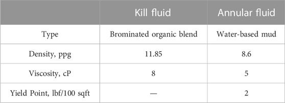
TABLE 1. Properties of kill and annular fluids in field-scale testing.
A total of 32 barrels of kill fluid (KF) was blended at the testing facility using three 550-gallon capacity oilfield mixing tanks. Also, a 20-barrel oilfield trip tank was used to prepare the annular fluid (AF). The mixed drilling mud was stored and hydrated in the tank for a week.
Fluid injection criteria
The KF injection was studied by considering injection geometry and the rate of stable settling of KF in the stagnant column of AF. The study involved bench-top testing with the slot model of annulus, described above (Demirci and Wojtanowicz, 2015; Demirci and Wojtanowicz, 2016a) and the pilot-scale testing with the annular 30-ft tall model, also mentioned above (Demirci and Wojtanowicz, 2016b). The slot-model tests utilized KFs and AFs with different viscosities and densities. They also considered two configurations for injecting KF at the top of the AF column: a sideward or downward injection. The results showed that sideward geometry was superior to the downward injection due to the impingement effect that provides stable settling of KF fluid droplets at higher injection rate without their break-up and partial loss in the upward overflow of AF.
The slot-model study also provided empirical formulas for maximum sideward injection rate for field-scale process design. Eq. 1 below gives the rate required for desired impingement flow and Eq. 2 gives the maximum rate for undesired atomization flow regime.
Understanding of the injection rate effect was improved with the pilot scale 20-ft high physical model of casing annulus designed and manufactured at the Albemarle Process Development Center. The model featured a 6-in [6 5/8-in. outer diameter)] carbon-steel pipe inside an 8-in. [8.329-in. inner diameter] carbon-steel pipe (Demirci and Wojtanowicz, 2016b). A total of 37 experiments were conducted with water-based AFs and brominated organic KFs with densities from 9 to 13 ppg and from 17 to 23 ppg, respectively. Also, an upward gas migration was allowed in some experiments having KF injected with no pressure at the top of the AF column.
The results showed that gas migration would prevent buoyant settling and fluid displacement at any injection rate. Thus, the buoyant kill process must be performed in the pressurized annulus to eliminate gas migration. Moreover, buoyant settling of KF produced a two-fluid mixture column on top of the settled KF column at the bottom of the annuls. The mixture length would build in time and its final size would increase at higher injection rate and smaller density difference of the two fluids. Density of the mixture column changed upwards exponentially from KF density to AF density. The results also indicated that more than one annular volume of KF would be needed to replace the AF in the annulus.
The experiments provided data for derivation of a pressure replacement model that would predict hydrostatic pressure increase at the bottom of the fluid column resulting from AF replacement with KF. A dimensionless parameter, Ru, is the ultimate displacement and represents the ratio of required kill fluid volume to annular volume for maximum annular pressure increase. The parameter value was empirically correlated using the experimental data (Demirci and Wojtanowicz, 2016b) as,
The formula shows increased usage of KF for higher injection rate caused by dispersion and loss of KF in the AF overflow. It also implies that there is a maximum low value of injection rate that would minimize volume of KF needed for maximum annular pressure increase due to efficient buoyant settling of KF without its partial dispersion in AF. Maximum injection rate is determined from the buoyant transport model based on the theory of fluid droplet slippage shown in Supplementary Appendix S1 as,
Field-scale demonstration test
The buoyant-kill process was demonstrated in Well#1 of the LSU Petroleum Engineering Research & Technology Transfer Laboratory. The experiment was conducted with the following objectives: to verify the process using a field-size well with long fluid column pressurized at the top (SCP), to evaluate process duration and efficiency of fluid displacement, and to test validity of the process up-scaling design model.
Well installation
Figure 2 is a photograph of top installation at the wellhead of Well#1. Downhole installation schematics is depicted in Figure 3. The wellhead photo in Figure 1 shows the KF injection pump with the KF feed line and 2-in. outlet pipe for overflow of the displaced AF. Also shown is the pipe for downhole injection of gas into the tubing (through the gas-lift valve) so the gas would migrate upwards in the tubing filled with AF liquid. The 2,750-ft long 2–7/8″ (ID = 2.441″) tubing shown in Figure 2 simulates column of AF having 16 barrels volumetric capacity. The tubing’s bottom represents the cement top conditions in actual well with the gas injection valve and two pressure transducers.
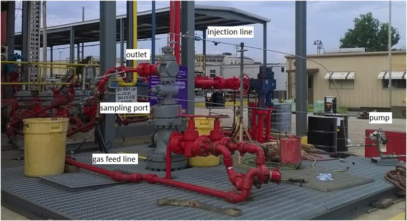
FIGURE 2. Surface view of test well’s surface installation.

FIGURE 3. Field-scale test well downhole installation.
The feed line for KF injection is a 0.5″ (ID = 0.375″) diameter microtubing stretching from the injection pump to the wellhead’s top (Figure 2) and going 60 feet down the tubing with an elbow-shaped outlet to assure KF discharge geometry with impingement (Figure 3). Pressure and rate capacities of the positive—displacement chemically—resistant KF injection pump are 900 psi and 9–90 gal/hr, respectively. The 2-in. overflow outlet pipe is equipped with a sampling port and a conductivity-meter to collect fluid samples and measure composition of the overflow stream. A pressure-temperature transducer at the outlet pipe controls constant pressure at the wellhead. The overflow is discharged to a mud-gas separator.
Testing procedure
1) Fill the tubing with 15.5 barrels of the mud by leaving 57 feet space at the top in order to create a gas cap and to assure submerged injection of kill fluid KF;
2) Close all valves and leave the mud in the tubing undisturbed (no gas injection) for 3 h to gain structural (gel) strength;
3) Set auto-choke pressure at 2,000 psi and start injecting gas through the gas lift valve.
4) Control wellhead pressure during gas migration with auto-choke to achieve its final value reduced to 350 psi i.e., simulated value of SCP; Note the initial value of bottom pressure (i.e., simulated pressure at the cement top);
5) Start slow injection of KF while checking the pressure readings;
6) Keep the bottom pressure constant by bleeding-off the choke pressure by 50 psi if the bottom pressure increases by 50 psi; Do not let bottom pressure drop below its initial value;
7) Collect fluid samples every 30 min to make sure that the AF is being displaced If KF is present in samples, reduce the KF injection rate;
8) Stop KF injection when the wellhead pressure drops to zero.
Shown in Figure 4 is the expected theoretical pressure change during the test: tubing fill-up with AF in Step 1; mud gelation in Step 2; pressure-controlled injection of gas in Steps 3; gas migration ending with simulated SCP of 350 psi in Step 4; and KF injection with step-wise bleeding of wellhead pressure in Step 5.
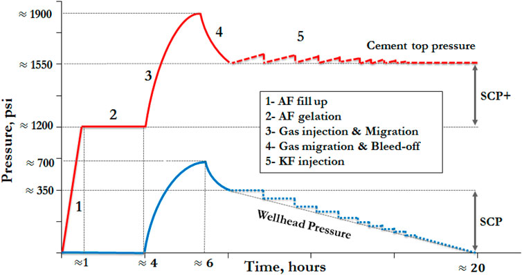
FIGURE 4. Expected pressure change during field-scale test.
Injection rate design
As learned from the previous tests, the efficiency of the displacement process strongly depends on the injection rate. The rate was designed using data from the bench-top testing with the slot model, the theoretical considerations, above, and additional lab verification.
The slot-model study (Demirci and Wojtanowicz, 2016a) included three runs with fluids in Table 1. All the runs showed high volumetric and pressure replacement efficiencies with the model’s annular capacity 1.05 gal/ft. To obtain similar performance in the field-scale test (tubing capacity 0.24 gal/ft) injection rate conversion is made by assuming the same settling velocity shown in Table 2. The assumption ignores different flow geometry in the slot model and the tubing with potential effects such as the whirling flow of heavy fluid through a lighter fluid discussed elsewhere (Calvert et al., 1995).
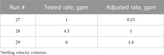
TABLE 2. Injection rate conversion from slot-model to field-scale testa.
Settling velocity criterion is further verified in the flip-flop experiment using a 4-foot long clear PVC pipe having diameter 2.5″ (2.323″ ID) and capacity (0.23 gal/ft) similar to the well’s tubing. In the experiment, the kill fluid in Table 1 was placed at the pipe’s bottom while filling the rest with AF form Table 1. Then, the pipe was flipped to have KF on top of AF and the displacement process was timed as shown in Figure 5.
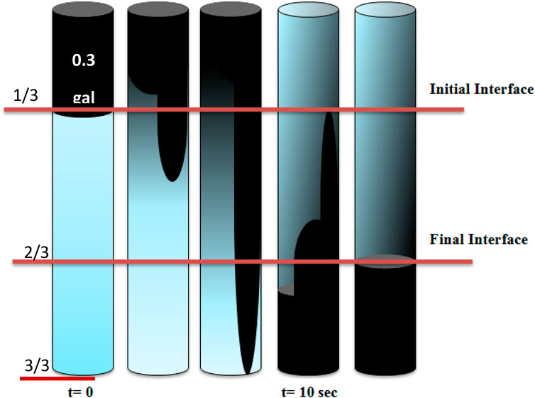
FIGURE 5. Flip-flop settling experiment with KF (black) and AF from Table 1.
After pipe flipping, the KF/TF interface broke and a plume of kill fluid started to slip downwards. The fluids’ interface produced KF droplets that settled down much slower than the plume. It took 10 s for the two fluids to be fully replaced so the required KF injection rate is estimated as,
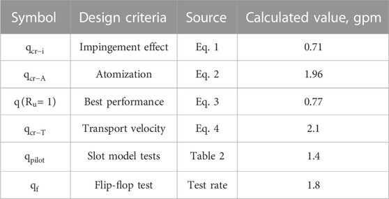
TABLE 3. Maximum KF injection rate for different criteria.
Another practical criterion for the KF injection rate design was the experiment’s duration time. Using the best-performance (minimum KF volume) criterion (Eq. 3) the time needed for displacing 16 barrels of AF at different injection rate is shown in Figure 6. Considering the importance of atomization criteria and trying to keep the operation time below about 12 h the KF injection would begin at 1.5 gpm with visual inspection of the KF content in the overflow in order to reduce the rate until only AF is present.
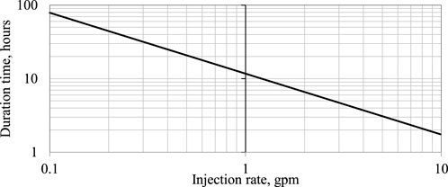
FIGURE 6. Duration of filed-scale experiment with minimum usage of KF.
Results and observations
Figure 7 shows the recorded change of downhole pressure (simulated top cement pressure) and the wellhead pressure during the test. Comparing with Figure 4 reveals that the overall change of the pressures (dotted lines) followed the expected trend, i.e., the wellhead pressure (SCP) reduction with no change of bottom pressure indicating partial removal of the simulated SCP by the fluids’ displacement. Also, the plots’ fluctuations reveal several problems such as irregular injection rate due the leaking feed line and malfunction of the pump. The most important problem, however, was the failure of the auto choke after 2.5 h of KF injection resulting in temporary decompression of the wellhead. (As a result, shown in Table 4, injection rate increased rapidly from 0.83 to 1.8 gal/m). It took several hours to reset the choke and restore wellhead pressure.
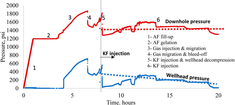
FIGURE 7. Pressure change during field-scale experiment.

TABLE 4. Kill fluid’s holdup in well and loss in overflow during field-scale test.
Efficiency of wellhead pressure removal is depicted in Figure 8 by comparing expected performance (dotted plots) with the actual one (solid plots). The pressure plots show a 150-psi reduction of the initial pressure of 360 psi. The efficiency plots indicate that up to 20% of injected KF was effectively used for the pressure reduction; The remaining KF little contributed to the removal. During the test, only part of injected KF was retained in the well while another part was getting lost in the overflow. The retained KF contributed to overall hydrostatic pressure buildup of the well’s fluid column.
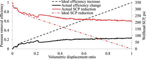
FIGURE 8. Actual and ideal change in
The plot in Figure 9 is the increase of pressure at the bottom of the well’s fluid column during the test resulting from KF entrainment. There are four trend lines representing four stages of hydrostatic pressure buildup. The plot shows stage-wise reduction of pressure buildup rate due to lesser entrainment of KF. Below, the pressure buildup data is analyzed to determine the fraction of KF volume retained in the well and the fraction lost in the overflow during the displacement process by considering the change of average density of the fluid column.
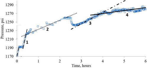
FIGURE 9. Downhole hydrostatic pressure change during then test.
For known values of KF injection rate and pressure buildup rate the fraction of the KF actually retained in the well is calculated as,
Where.
A = tubing capacity in gal/ft,
Analysis of the well’s hydrostatic pressure buildup is summarized in Table 4. The data show progressive deterioration of the displacement process in terms of reduced KF retainment and increased density of the overflow.
Discussion
The results highlight the importance of maintaining small and stable KF injection rate. Excessive rate would cause KF dispersion in AF forming emulsified mixture that would flow upwards and return in the overflow. Also, the emulsified mixture column at the KF injection exit may bridge-over the AF column and prevent/reduce buoyant slippage. Unstable KF injection rate involves fluctuation of pressure resulting in gas migration that blocks buoyant settling demonstrated in the pilot-scale tests (Demirci and Wojtanowicz, 2016b, and 2017).
Effect of pump pulsation
The pneumatic positive displacement pump used for KF injection generates pressure pulses that result in fluctuation of flow rate. (The fluctuations were averaged in the flow meter readings.) The fluctuating rate repeatedly exceeded the maximum designed flow rate by going above the atomization flow regime threshold (Table 3) which resulted in dispersion of KF droplets. Instead of traveling to the bottom, the droplets floated in the well’s fluid column plugging it off and disrupting the KF settling transport.
Effect of gas flotation
Accidental wellhead’s decompression resulted in gas migration and entrapment in AF. Releasing the well-head pressure would reduce the pressure on top of trapped gas bubbles and allow them to expand. Expanding gas bubbles would; 1) decrease the density of the fluid column, 2) start migrating upwards. The similar phenomenon was actually tested in the pilot scale experiments where KF injection during gas migration resulted in poor displacement (Demirci and Wojtanowicz, 2017). In this experiment, gas migration resulted from temporary failure of the auto choke causing wellhead’s decompression and bottom gas invasion. The migrating gas caused flotation of the emulsified mixture column around the KF exit.
Conclusion
• The test confirmed viability of the Buoyant Kill technique for SCP removal. The overall change of the simulated pressure at the wellhead and the cement top followed the expected trend, i.e., the wellhead pressure (SCP) was reduced without no change of the bottom-hole pressure indicating partial removal of the simulated SCP by the fluids’ displacement.
• The SCP removal process was not complete due to accidental wellhead decompression and fluctuations od the kill fluid injection rate resulting from pump pulsation.
• Decompression of the wellhead, caused by the auto choke failure, invoked gas migration and flotation-based removal of the injected kill fluid. The Buoyant Kill technique requires reliable pressure control at the wellhead.
• Pump pulsation caused dynamic injection rate fluctuations, dispersion of the kill fluid in the well’s fluid annular, and incomplete buoyant settling. A steady and low-rate injection of the kill fluid is critical for successful field application of the technique.
• Despite complications, almost 30% of the injected kill fluid was retained in the well and pressure of the well’s fluid column significantly increased. The results show that complete removal of SCP is possible with only partial retainment of kill fluid in the well.
• Hydrophobic brominated organic liquids are promising candidates for field applications of the Buoyant Kill technique considering their wide range density (11–25 ppg), highly variable viscosity (0.5–3,000 cP)—critical properties for effective buoyant settling.
Data availability statement
The raw data supporting the conclusion of this article will be made available by the authors, without undue reservation.
Author contributions
ED: Conceptualization, Investigation, Methodology, Data curation, Software, Writing–original draft. AW: Conceptualization, Investigation, Methodology, Formal Analysis, Funding acquisition, Project administration, Resources, Supervision, Validation, Writing–review and editing.
Funding
The author(s) declare financial support was received for the research, authorship, and/or publication of this article. Financial support for this study has been provided by the Louisiana State University Sustained Casing Pressure Program funded jointly by Shell Oil Corporation (The funder was not involved in the study design, collection, analysis, interpretation of data, the writing of this article, or the decision to submit it for publication.) and Albemarle Corporation that also manufactured the experimental model and supplied heavy fluids for the experiments.
Acknowledgments
Our deepest appreciation goes to Dr. Kristina Butler of Albermarle Corporation for designing the kill fluid and supervising the experiment. We specially thank the LSU PERTT Lab staff and student workers for advice and help in the experiment.
Conflict of interest
The authors declare that the research was conducted in the absence of any commercial or financial relationships that could be construed as a potential conflict of interest.
The authors also declare that this study received funding from Albemarle Corporation. The funder had the following involvement in the study: (1) Provided kill fluid for the field-scale demonstration test, (2) Participated in the test; and (3) collected waste fluids after the test.
Publisher’s note
All claims expressed in this article are solely those of the authors and do not necessarily represent those of their affiliated organizations, or those of the publisher, the editors and the reviewers. Any product that may be evaluated in this article, or claim that may be made by its manufacturer, is not guaranteed or endorsed by the publisher.
Supplementary material
The Supplementary Material for this article can be found online at: https://www.frontiersin.org/articles/10.3389/fenrg.2023.1309207/full#supplementary-material
References
Achang, M., Yanyao, L., and Radonjic, M. (2020). A review of past, present, and future Technologies for permanent plugging and abandonment of wellbores and restoration of subsurface geologic barriers. Environ. Eng. Sci. 37 (6), 395–408. doi:10.1089/ees.2019.0333
Bourgoyne, A. T., Scott, S. L., and Manowski, W. (2000). A review of sustained casing pressure occurring on the OCS. Avaliable at: https://www.wellintegrity.net/Documents/MMS%20-%20Review%20of%20SCP%20-%202000.pdf.
Bozzano, G., and Dente, M. (2009). Single bubble and drop motion modeling. Proc. AIDIC Conf. Ser. 9, 54–60. doi:10.3303/ACOS0909007
Calvert, D. G., Heathman, J. F., and Griffith, J. E. (1995). “Plug cementing: horizontal to vertical conditions,” in Presented at the SPE annual technical conference and exhibition (Dallas, Texas: SPE), 22–25. doi:10.2118/30514-MS
Carpenter, R. B., Gonzalez, M. E., Granberry, V., and Becker, T. E. (2004). “Remediating sustained casing pressure by forming a downhole annular seal with low-melt-point eutectic metal,” in Presented at the IADC/SPE drilling conference (Dallas, Texas: SPE-87198-MS), 2–4.
Clift, R., Grace, J. R., and Weber, M. E. (2005). Bubbles, drops and particles. New York: Dover Publications.
Crowe, C. T. (2006). Multiphase flow Handbook. first edition. Boca Raton, FL: Taylor & Francis/CRC Press.
Dedegil, M. Y. (1987). Drag coefficient and settling velocity of particles in non-Newtonian suspensions. J. Fluids Eng. 109 (3), 319–323. doi:10.1115/1.3242667
Demirci, E., Butler, K., and Wojtanowicz, A. K. (2017). “Development of well intervention fluid for removal of sustained casing pressure,” in Proc ASME 36th international conference on ocean, offshore & arctic engineering (Trondheim, Norway: Polar and Arctic Sciences and Technology; Petroleum Technology), V008T11A034. doi:10.1115/OMAE2017-62600
Demirci, E., and Wojtanowicz, A. K. (2015). “Laboratory visualization of gravity fluid displacement in well annulus affected by sustained casing pressure,” in Proc ASME 34th international conference on ocean, offshore and arctic engineering (Newfoundland, Canada: Petroleum Technology), V010T11A020. doi:10.1115/OMAE2015-42319
Demirci, E., and Wojtanowicz, A. K. (2016a). Pilot size process visualization: gravity fluid displacement method to stop annular gas migration. J. Nat. Gas Sci. Eng. 29, 223–231. doi:10.1016/j.jngse.2015.12.051
Demirci, E., and Wojtanowicz, A. K. (2016b). “Pilot-scale study of buoyant settling of immiscible heavy fluid in mud – a promising technique to stop annular gas migration above leaking cement,” in Presented at the SPE EUROPEC at 78th EAGE conference and exhibition (Vienna, Austria: SPE-180145-MS). doi:10.2118/180145-MS
Demirci, E., and Wojtanowicz, A. K. (2017). Pilot-scale experimental study and mathematical modeling of buoyant settling of immiscible heavy fluid in mud to stop annular-gas migration above leaking cement. SPE J. 23, 186–204. doi:10.2118/180145-PA
Di Felice, R. (1994). The voidage function for fluid-particle interaction systems. Int. J. Multiph. Flow 20, 153–159. doi:10.1016/0301-9322(94)90011-6
Horton, R. L., Powell, J. W., Foxenberg, W. E., and Kippie, D. (2004). Remediation treatment of sustained casing pressure (SCP) in wells with top down surface injection of fluids and additives. US Patent No. WO 2004038164 A2.
Kaneda, Y. (1986). The drag on a sparse random array of fixed spheres in flow at small but finite Reynolds number. J. Fluid Mech. 167, 455–463. doi:10.1017/s0022112086002914
Khattak, M. A., Jain, B., Kalbani, S. A., Ahmed, J., Afrianto, A. A., Qassabi, N., et al. (2015). “Use of novel self-healing materials to control sustained casing pressure and prevent long term environmental impact,” in Presented at the SPE annual technical conference and exhibition (Houston, Texas: SPE-174892-MS). doi:10.2118/174892-MS
Koch, D. L., and Hill, R. J. (2001). Inertial effects in suspension and porous media flows. Annu. Rev. Fluid Mech. 33, 619–647. doi:10.1146/annurev.fluid.33.1.619
Koch, D. L., and Sangani, A. S. (1999). Particle pressure and marginal stability limits for a homogeneous monodisperse gas-fluidized bed: kinetic theory and numerical simulations. J. Fluid Mech. 400, 229–263. doi:10.1017/s0022112099006485
Kupresan, D., Heathman, J., and Radonjic, M. (2014). “Experimental assessment of casing expansion as a solution to microannular gas migration,” in Presented the IADC/SPE drilling conference and exhibition (Forth Worth, Texas: SPE-168056-MS). doi:10.2118/168056-MS
Landry, G., Welty, R. D., Thomas, M., Vaughan, M. L., and Tatum, D. (2015). “Bridging the gap: an integrated approach to solving sustained casing pressure in the cana woodford shale,” in Presented at the SPE well integrity symposium (Galveston, Texas: SPE-174525-MS). doi:10.2118/174525-MS
Milanovic, D., and Smith, L. (2005). “A case history of sustainable annulus pressure in sour wells - prevention, evaluation and remediation,” in Presented at the SPE ATW HPHT sour well design applied technology workshop (The Woodlands, Texas: SPE-97597-MS). doi:10.2118/97597-MS
Nishikawa, S. (1999). Mechanism of gas migration after cement placement and control of sustained casing pressure. MS Thesis. Baton Rouge, Louisiana: Louisiana State University.
Nishikawa, S., Wojtanowicz, A. K., and Smith, J. R. (2001). “Experimental assessment of the bleed-and-lube method for removal of sustained casing pressure,” in Presented at the Petroleum society's Canadian international Petroleum conference (Calgary, Alberta, Canada: PETSOC-2001-041). doi:10.2118/2001-041
Obodozie, I. E., Trahan, S., and Joppe, L. C. (2016). “Eliminating sustained casing pressure in well abandonment,” in Presented at the offshore technology conference asia (Kuala Lumpur, Malaysia: OTC-26432-MS). doi:10.4043/26432-MS
Richardson, J. F., and Zaki, W. N. (1954). The fall velocities of spheres in viscous fluids. Trans. Inst. Chem. Eng. 32, 35–41.
Saltel, B., Gonzalez, L., McIntosh, T., and Weems, M. (2015). “Restoring casing integrity using an expandable steel patch prior to drilling ahead with minimal reduction of next hole size,” in Presented at the SPE well integrity symposium (Galveston, Texas: SPE-174524-MS). doi:10.2118/174524-MS
Scott, S. L., Regg, J. B., and Bourgoyne, A. T. (1999). “Sustained casing pressure in offshore producing wells,” in Presented at the offshore technology conference (Houston, Texas: OTC-11029-MS). doi:10.4043/11029-MS
Seyyedi, M., Mahmud, H. K. B., Verrall, M., Giwelli, A., Esteban, L., Ghasemiziarani, M., et al. (2020). Pore structure changes occur during CO2 injection into carbonate reservoirs. Sci. Rep. 10 (1), 3624. doi:10.1038/s41598-020-60247-4
Shadravan, A., and Amani, M. A. (2015). “Decade of self-sealing cement technology application to ensure long-term well integrity,” in Presented at the SPE Kuwait oil & gas show and conference (Mishref, Kuwait: SPE-175237-MS). doi:10.2118/175237-MS
Soter, K., Medine, F., and Wojtanowicz, A. K. (2003). “Improved techniques to alleviate sustained casing pressure in a mature Gulf of Mexico field,” in Proc. SPE annual technical conference and exhibition (Denver, Colorado: SPE-84556-MS). doi:10.2118/84556-MS
Taleghani, A. D., and Santos, L. (2023). Wellbore integrity: from theory to practice. Switzerland: Springer Nature.
Tanoto, E., Kusumawatie, R., Widyarsa, I., and Jaffery, M. F. (2016). “Enhancing zonal isolation with expandable cement system for gas fields,” in Presented at the IADC/SPE asia pacific drilling technology conference (Singapore: IADC/SPE-180527-MS). doi:10.2118/180527-MS
Wajid, A., Al-Turki, F. A., Abbas, A., Al-Yami, A. S., Wagle, V., and Dahmoush, A. A. (2022). “Resin systems as evolving solution within the industry to replace the conventional remedial cementing while eliminating the sustained casing pressure SCP,” in International Petroleum technology conference (Riyadh, Saudi Arabia: IPTC-21953-EA). doi:10.2523/IPTC-21953-EA
Wen, C. Y., and Wu, Y. H. (1966). Mechanics of fluidization. Chem. Eng. Prog. Symp. Ser. 62, 100–125.
Wojtanowicz, A. K., Nishikawa, S., and Rong, X. (2001). Diagnosis and remediation of sustained casing pressure in wells. Herndon, VA: US Department of Interior Minerals Management Service.
Yan, W., Wei, H. G., Muchiri, N. D., Li, F. L., Zhang, J. R., and Xu, Z. X. (2023). Degradation of chemical and mechanical properties of cements with different formulations in CO2-containing HTHP downhole environment. Petroleum Sci. 20 (2), 1119–1128. doi:10.1016/j.petsci.2023.03.012
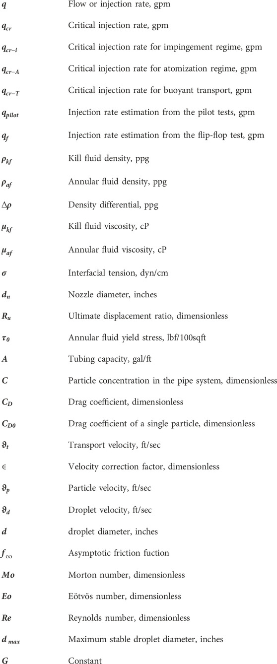
Nomenclature
Keywords: well integrity, sustained casing pressure, SCP, well cement failure, well completion efficiency
Citation: Demirci E and Wojtanowicz A (2023) Design and field-scale demonstration of the buoyant-kill process for restoring integrity of wells with sustained casing pressure. Front. Energy Res. 11:1309207. doi: 10.3389/fenrg.2023.1309207
Received: 08 October 2023; Accepted: 07 November 2023;
Published: 27 November 2023.
Edited by:
Arash Dahi Taleghani, The Pennsylvania State University (PSU), United StatesReviewed by:
Wenlong Jia, Southwest Petroleum University, ChinaMingqiang Wei, Southwest Petroleum University, China
Copyright © 2023 Demirci and Wojtanowicz. This is an open-access article distributed under the terms of the Creative Commons Attribution License (CC BY). The use, distribution or reproduction in other forums is permitted, provided the original author(s) and the copyright owner(s) are credited and that the original publication in this journal is cited, in accordance with accepted academic practice. No use, distribution or reproduction is permitted which does not comply with these terms.
*Correspondence: Andrew Wojtanowicz, YXdvanRhbkBsc3UuZWR1
†Present address: Efecan Demirci, Wartsila Corporation, Istanbul, Türkiye