 Weikai Yi1
 Qihang Li
 Wei Liu
- 1SINOPEC Research Institute of Petroleum Engineering Co., Ltd., Beijing, China
- 2State Key Laboratory of Coal Mine Disaster Dynamics and Control, Chongqing University, Chongqing, China
The Sanshui salt mine is the sole location in the Guangdong province of South China with the potential to construct a salt cavern gas storage (SCGS) facility. Nevertheless, the gas storage construction of this mine faces significant challenges due to the presence of low‒grade salt deposits and numerous interlayers. To demonstrate the feasibility and calculate the gas storage capacity in this specific mining area, two representative salt caverns within this salt mine were simulated using a self-developed cavern-building simulation program, enabling us to accurately determine their respective volumes and shapes. Herein, the findings indicate that the combined caverns possess a total mining space volume of 1,157,000 m3, with the brine space accounting for merely 291,800 m3 (representing 25.22% of the overall mining space), and an extensive sedimentary volume of 865,200 m3 is also observed (constituting approximately 74.78% of the total mining capacity). Fortunately, this study has revealed that the sediments exhibit a porosity exceeding 40% and possess favorable permeability; consequently, countermeasures have been proposed to enhance the gas storage capacity within the pore space of these caverns, and we also utilized FLAC3D software for numerical simulation calculations to compare the stability of the cavern under different conditions of sediment pore utilization by calculating the volume loss rate, cavern wall displacement deformation, and plastic zone distribution. Moreover, the proposed method is anticipated to double the caverns’ working gas volume, increasing it from 40 million m3 to nearly 80 million m3. On the other hand, the long-term stability of caverns is numerically assessed under different pore space utilization rates of the sediments. The results also indicate that the caverns’ volume shrinkage, plastic zones, and surrounding rock displacement remain within allowable limits during 30 years of gas storage operation. The primary problem in the subsequent phase lies in effectively achieving gas injection and brine removal from the pore space of sediments while devising a methodology to extend this method to other salt caverns within similar salt mine areas. Thus, this study provides theoretical and technical guidance for the establishment of gas storage in existing salt caverns in the Sanshui salt mine and in salt mines worldwide that share similar geological conditions.
1 Introduction
Natural gas has the characteristics of high calorific value, low carbon emission, and virtually no dust, thus earning praise as a high-quality clean energy resource. Increasing the proportion of natural gas in the national energy structure is of great significance for promoting carbon emission reduction and environmental protection (Zárante and Sodré, 2009; Wu et al., 2021; Li et al., 2023). The annual consumption of natural gas in China has been steadily increasing. For example, in 2000, China’s annual consumption of natural gas was only 23.8 billion m3, and in 2020, this consumption reached 328 billion m3 (Liu et al., 2020), with a cumulative increase of 1,278.15% and an average annual growth rate of 63.91%. Nevertheless, at present, the proportion of natural gas in China’s primary energy is merely 8.4%, which is still far from the global average of 24%. Natural gas is the most realistic and clean transition energy from fossil energy to non-fossil energy, and its consumption will continue to increase for a long time.
Conventional natural gas resources in China are limited, and the external dependence of natural gas reached 45.1% in 2020. There are still many difficulties and challenges to ensure sufficient supply of natural gas in China. Because the country’s foreign dependence on natural gas remains at a high level, the supply of natural gas in the domestic market is blocked, which usually leads to large fluctuations in natural gas prices (Jong, 2015). For instance, during the conflict between Russia and Ukraine in 2022, the price of natural gas in Europe soared to 240 euros/MW (approximately RMB 16.8 Yuan/m3) (Zheng et al., 2023). To ensure a stable supply of natural gas and maintain market equilibrium, two measures are commonly implemented. First, the exploration and development of civil natural gas is strengthened. For example, in recent years, China has stepped up the exploration and development of unconventional natural gas (Mcglade et al., 2013), such as shale, coalbed methane, and tight sandstone gas, which has achieved initial success in field production. However, it is still not enough to meet the country’s increasing demand for natural gas. The second approach involves expediting the construction of gas storage and enhancing operational efficiency (Yang et al., 2022). This can be achieved by using diverse underground reservoirs/structures (Evans and Brooks, 2021; Li et al., 2022a), which serves as a robust measure to directly guarantee natural gas supply and stabilize the price.
A salt cavern is a widely used type of natural gas storage (Van et al., 2014), and it is an underground space built in salt formations by utilizing water solution mining technology. Currently, many countries, such as Germany, France, Britain, the United States, Canada, and China, have built salt cavern gas storage (SCGS) facilities. Compared with the other two popular gas storage types, depleted gas reservoir and aquifer gas storage, SCGS has the advantages of high injection-production frequency, less cushion gas volume, and clear gas storage boundary (Yang et al., 2009; Liu et al., 2019), which has gained much attention in recent years. As for the existing gas storage facilities in China, most of them are located in the western and northern regions, while in the vast southern regions (Yang et al., 2009; Liu et al., 2020), there are no large underground gas storage sites. It is of great significance to build gas storage sites in the vast southern regions of China to maintain regional energy security.
At the beginning of this century, China began to build SCGS. In 2007, the first SCGS was completed and put into operation in the Jintan salt mine, Jiangsu Province. By the end of 2022, Jintan SCGS has produced more than 5 billion m3 of natural gas (Liu et al., 2021), which plays an important role in maintaining gas supply in the Yangtze River Delta region. Nevertheless, except for Jintan, the construction of gas storage in salt caverns in China started late and the progress was not smooth. The reason is that the geological conditions of salt mines in China are complicated, with many interlayers, thin salt layers, and low salt rock grades (Zhou et al., 2011; Li et al., 2022b). In these salt formations, it is difficult to meet the basic requirements of cavern construction by copying the theory and technology of storage construction in formations of salt dome strata in Europe and America. For instance, the cavern height in the West Hackberry of the United States is as high as 600 m, but the height of salt caverns in China is only 100 m. In addition, the previous gas storage projects in salt caverns in China were mainly newly planned and constructed, but the thousands of existing old caverns were still rarely utilized (Liu et al., 2016).
Therefore, in view of the complex bedded salt rocks in China, it is necessary to find a way to break through the bottleneck of cavern construction, develop new methods for cavern construction and gas storage (Ren et al., 2014; Fu et al., 2018; Wang et al., 2021), and actively utilize the existing abandoned salt caverns to store natural gas. It is not a new concept to use abandoned salt caverns for gas storage. The first phase of the Jintan salt cavern gas storage project utilized six old caverns to store natural gas (Yang et al., 2015). Additionally, the first phase of the strategic petroleum reserve (SPR) in the United States also used several old caverns to store crude oil (Sobolik and Lord, 2015). As shown in Figure 1, an old salt cavern with satisfactory injection-production conditions can also be used as a gas storage space. Using old caverns can not only save the time and investment of cavern construction but also improve the safety of these caverns, thereby reducing possible geological disasters, such as roof damage, brine leakage, and excessive ground subsidence. Thus, we propose to use old salt caverns in Sanshui to support natural gas storage.
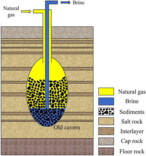
FIGURE 1. Schematic diagram of the old SCGS.
In this study, two existing old caverns in the Sanshui salt mine in Guangdong province are taken as the research object. The formation conditions of the salt mine are analyzed, and the water solution mining process of the old caverns is simulated using self-developed simulation software, and the shape and volume of the salt caverns are obtained. Herein, FLAC3D software develops the VC program “Layered Salt Horizontal Solution Leaching Simulation Program” (HSLS) using the finite volume method (Yang et al., 2015). In HSLS, the main calculation parameters include the dissolution rate of the cavern boundary, the coordinates of the control points on the cavern surface, the flow and concentration field of brine, the height and mass of insoluble sediments, and the angle of the salt–brine interface. To improve the gas storage capacity of these old caverns, the proposition of utilizing sediment pore space for natural gas storage is proposed, along with an analysis of viable technologies to implement this concept. Accordingly, the relevant research provides basic data and a theoretical basis for the cavern stability evaluation and cavern reconstruction of the old SCGS in the Sanshui salt mine.
2 Basic information
The Sanshui salt mine is located in the northern part of the Pearl River Delta Economic Zone, 17 km away from Sanshui District, Foshan City (Figure 2). The traffic in the mining area is very convenient, connecting with Guangzhou, Foshan, Zhaoqing, and other cities by highways and railways. This salt mine has been mined for more than 20 years. Two salt companies are operating the mining business of the salt mine, and approximately 20 wells have been drilled to exploit the underground salt resources by the water solution method.
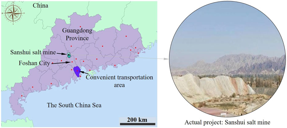
FIGURE 2. Geographical distribution map of the Sanshui salt mine.
2.1 Geological conditions of the salt mine
The Sanshui salt mine is located in the Sanshui Basin, which is the secondary structure unit. The salt mining area spans approximately 18 km2. There are 1–11 salt-bearing strata in the Sanshui salt mine. In this paper, four brine production wells, S1, S2, S3, and S4, are studied, which are all located in the Huanghua block of the Sanshui salt mine. Well S1 exposed all the salt-bearing strata in this block. Herein, the total thickness of the salt-bearing strata is 250 m, which consists of salt layers and mudstone interlayers. The buried depth of the salt layers is more than 1,210 m, and the maximum cumulative thickness of the salt layers is 126 m. In addition, according to the characteristics of each salt layer and the mining conditions of the Huanghua block, the salt layers above the No.8 salt layer were mined by S1‒S4 and S2‒S3, and the well section below the No.7 salt layer (excluding the No.7 salt layer) was sealed with cement (Table 1).
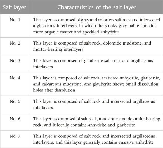
TABLE 1. Seam information about the Sanshui salt mine from No.1 to No.7.
2.2 Salt mine exploitation
(1) Well group S1‒S4
Well S1 and well S4 were originally mined separately, and both were vertical wells in the initial stage of mining. Because the distance between the two wells is close (70 m), after a period of mining, these two wells were connected by underground caverns. Subsequently, one of the two wells was utilized to inject fresh water and the other was used to extract brine.
Mining history of well S1: since 2000, this well has been producing brine through the water solution method. From 2000 to 2005, brine was mined for 61 months, and the cumulative salt production (NaCl) was 58,941.48 tons. From March 2005 to December 2016, brine was extracted by water injection for 153 months, and the caverns formed by the two wells were connected in March 2005. Since then, well S4 has been used for water injection, while well S1 was used for brine extraction; solution mining was turned into the double vertical well method, and the cumulative salt extraction amount was 498,848.62 tons.
Mining history of well S4: brine production was started in January 2000 and lasted until February 2005 (approximately 61 months), and the cumulative salt production of this well was 99,900.5 tons. Because the salt layers in well S4 are thicker, the salt production of well S4 within the same time was 40,959.02 tons more than that in well S1. From March 2005 to December 2016, the two wells were connected and well S4 was used as a water injection well, so the salt production of well S4 was merged into that of well S1.
The mining process of well group S1‒S4 can be described as follows: before the two wells were connected, they were all mined as individual wells, which can be simulated as single-well mining. After the two wells were connected by their underground caverns, the mining mode was converted into a double-vertical well, with well S4 used as the water injection well and well S1 used as the brine extraction well. The salt layers corresponding to well S4 are thicker and have a higher salt content than that of well S1, so it is reasonable to choose well S4 for water injection. Moreover, due to the large distance between the two wells, there is a large insoluble area between the caverns of the two wells. In the future, we can consider switching injection–extraction technology to realize the expansion of salt caverns in well S1 and the dissolution of the inter-well area to ensure the enlargement of the salt cavern. At the same time, due to the large output of well S4, it is also necessary to protect the roof of the cavern to ensure that a sufficient protective salt layer is reserved for gas storage in the later stage. Figure 3 shows that the dip angle of the salt layers between well S1 and well S4 is small, and thus, the salt layers are considered horizontal in the later simulation process.
(2) Well group S2‒S3
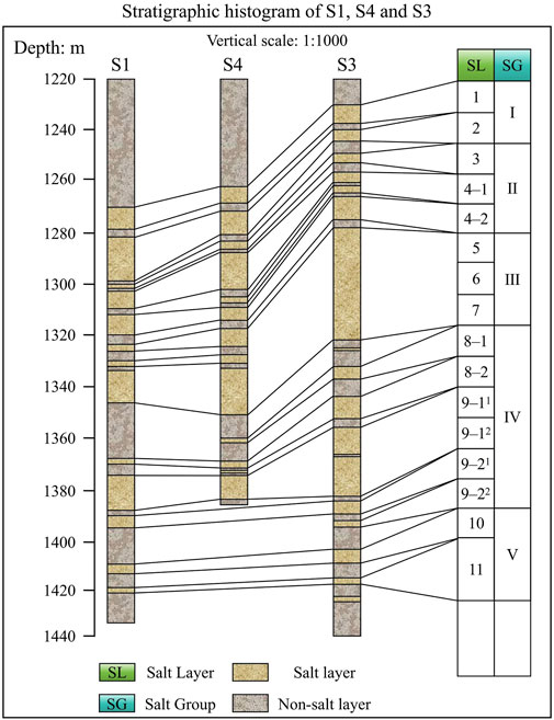
FIGURE 3. Geological histogram of salt layer distribution in the Sanshui salt mine.
During the production process of well group S2‒S3, well S3 was mined first, and the vertical well method was used at the early stage of mining. After a period of mining, a directional horizontal well, which is well S2, was drilled to connect the cavern formed by well S3.
Mining history of well S3: the construction of well S3 began in 2001, aiming at finding out further information about salt layers in the Huanghua block and improving salt production. The trial production began in the second half of 2002. By the end of December 2005, the cumulative salt production (NaCl) was approximately 51,161.51 tons. Subsequently, well S3 was connected with well S2.
Mining history of well S2: well S2 was drilled as a directional horizontal directional well in 2005. The surface wellhead distance between well S2 and well S3 was 180 m. From January 2006 to December 2018, the salt production of well S2 was merged with well S3, and the cumulative salt production (NaCl) was approximately 777,661.2 tons.
3 Mining simulation
3.1 Simulation scheme
The basic mining parameters of the four wells are shown in Tables 2. These parameters are derived and set according to the field data. The solution mining of the four wells was simulated using the self-developed cavern-building simulation program (Li et al., 2019). This program is specially designed to simulate cavern leaching in bedded salt rock, and it is capable of dealing with the cavern boundary expansion in impure salt formations, the collapse of interlayers, and the accumulation of sediments in the cavern bottom. In this program, it is assumed that the expansion of the salt cavern is mainly caused by the dissolution of salt rock, and the dissolution rate of salt rock is calculated by the following equation:
Here, v is the dissolution rate of the salt cavern, mm/h; vf is the dissolution rate of an ideal vertical salt surface, mm/h; C is the concentration of the brine, g/L; Cs is the concentration of the saturated brine, g/L; and α is the angle of the salt‒brine interface, °.
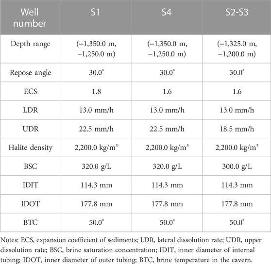
TABLE 2. Basic mining parameters of the four wells in the Sanshui salt mine.
For the concentration of brine in the cavern, a simplified model was established, and the brine in the cavern is divided into three main zones: the circulation zone above the injection tubing, the dead zone below the injection tubing, and the layer transition zone between the two zones. The conservation equations of concentration mass are shown as follows:
Here, ρ is the density of salt rock, kg/m3; Vm is the volume of the circulation zone, m3; t is time, h; u is the content of the insoluble substances of the salt, %; Vd is the volume of the dead zone, m3; Id is a factor, which is 1 in the direct leaching mode and 0 in the reverse leaching mode; Q is the injection flow rate, m3/s; V is the volume of a micro-element in the transition zone, m3; and q is the flow rate of the micro-element in the z-direction in the transition zone, m3/s.
The maximum tensile strength criterion is utilized to judge the collapse of the overhanging interlayer, and the tensile stress of the interlayer is calculated based on the cantilever beam theory. The judgment equation is as follows:
Here, σ is the tensile stress of the overhanging interlayer, MPa; σt is the tensile strength of the overhanging interlayer, MPa, which can be obtained by laboratory experiments and feedback corrections; M is the bending moment, KN/m; b is the thickness, and h is the height, m.
This program can also handle boundary expansion with or without the oil blanket. Therefore, in this study, we used this program to simulate the solution process of these four wells. Considering that the sediments are porous material, the expansion coefficient of sediment is set in advance, and a model for calculating the sediments’ volume is added to the program (Schwab et al., 2023).
3.2 Simulation results
(1) Well group S1‒S4
Well S1 and well S4 are combinations of exploration and production, and they are naturally connected to form a connected well group with a horizontal distance of 70 m. According to the aforementioned mining parameters (Table 2), the cavern leaching simulation of well group S1‒S4 was carried out. In the original stage, wells S1 and S4 were used to individually extract brine, respectively, and two separate corresponding caverns were formed underground. After a period of brine leaching, the two caverns were connected to form a big one, and the two wells formed a connecting well group. At the last stage of production, the simulated cavern shape of well group S1‒S4 was obtained, as shown in Figure 4.
(2) Well group S2‒S3
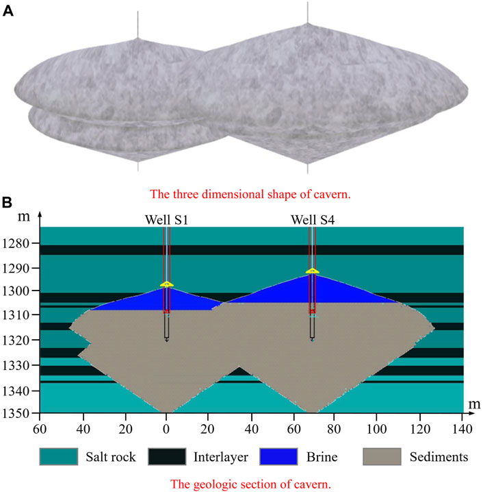
FIGURE 4. Mining simulation results of the well group S1‒S4.
The salt mining in the well group S2‒S3 adopts the two-butted-well method. Well S3 is a vertical well, extending downward from the surface of the ground to a depth of 1,344 m, and well S2 is a directional horizontal well. Moreover, the horizontal distance between these two wells is 180 m from the ground and approximately 50 m underground. The simulation result of cavern leaching is shown in Figure 5. As can be seen, an irregular horizontal cavern was formed, and most of the cavern space has been occupied by sediments. Compared with the cavern in well group S1‒S4, the cavern in the well group S2‒S3 has a much larger volume for brine, while the sediments have a non-planar surface under the brine space.
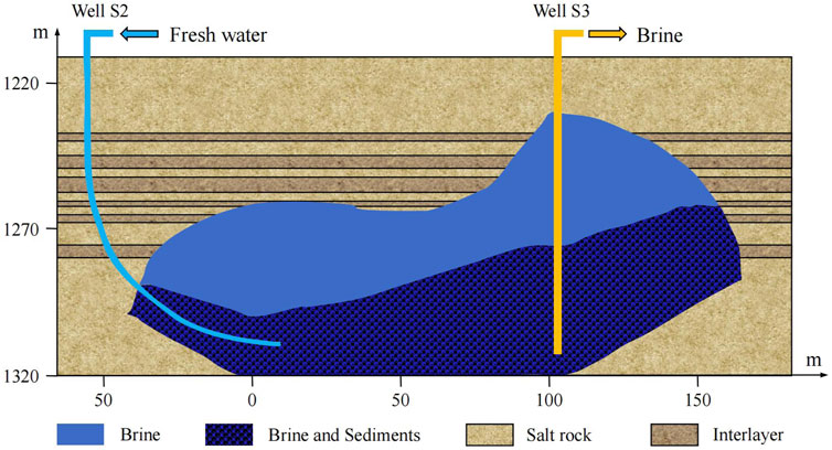
FIGURE 5. Mining simulation results of the well group S2‒S3.
4 Cavern volume and gas storage capacity
In Section 3, based on the salt mining data on the salt mine site, the final shape of the underground salt cavern is inversed using the self-developed simulation program according to the on-site data on salt mining. Subsequently, in this part, the cavern volume of the underground salt caverns is further studied, and their gas storage capacity is analyzed.
4.1 Cavern volume
(1) Well group S1‒S4
Simulation results of well S1: the total mining volume VTotal is 15.97 × 10⁴ m3, the sediment volume VSedi is 15.81 × 10⁴ m3, and the brine volume VBrine is 0.16 × 10⁴ m3. The sediment accounts for 99% of the total volume, and the brine space only accounts for 1% of the total mining volume.
Simulation results of well S4: the total mining volume VTotal is 24.85 × 10⁴ m3, the sediment volume VSedi is 21.87 × 10⁴ m3, and the brine volume VBrine is 2.98 × 10⁴ m3. The sediment space accounts for 88% of the total volume, and the net brine space only accounts for 12% of the total volume.
After conducting the aforementioned analysis, it is evident that the cumulative volume of the well group S1‒S4 cavern amounts to 40.82 × 10⁴ m3, with a sedimentary volume totaling 37.68 × 10⁴ m3; however, the net volume stands at a mere 3.14 × 10⁴ m3. Considering that well S4 was used for water injection and well S1 was used for brine extraction in the later period, the cavern of well S1 changed much less than the cavern of well S4. Although most of the cavern space is filled with sediments, the process of water injection and brine extraction was always smooth, both in the field and in our simulation process, which indicates that the sediments have good porosity and excellent permeability.
The coefficient of debris expansion of the sediments usually reaches 1.6–1.8 (Wu et al., 2021), followed by the porosity of the sediments, which can be calculated by the following equation:
Here, ϕ is the porosity of sediments, and η is the expansion coefficient of the sediments.
Using Eq. 4, the porosity of the sediment is calculated, and the porosity is as high as 37.5%–44.4%, indicating that there is a lot of pore space in the sediments. The simulation results presented in Figure 5 indicate a negligible thickness of the residual salt layer above the cavern roof of well S4. If the expansion of the cavern boundary would like to be reformed in the future, it is recommended to inject water from well S1 and to extract brine from well S4. If feasible, it is recommended to use roof protection measures such as an oil or gas blanket (Wan et al., 2020; Li et al., 2022e).
(2) Well group S2‒S3
Simulation results of well group S2‒S3: the total mining volume VTotal is 78.45 × 10⁴ m3, the sediment volume VSedi is 52.68 × 10⁴ m3, and the brine volume VBrine is 25.77 × 10⁴ m3. The sediments account for 67.15% of the total volume, and the volume of brine space accounts for 32.85% of the total volume. The cavern mainly appears on the side of the inclined well S2, where the salt rock has a higher grade and smaller proportion of interlayer, so the sediment volume is greatly reduced, and the brine space is improved. Nevertheless, considering that the volume of sediments occupies as high as 67.15% of the total mining volume, it remains imperative to fully utilize the pore space within these sediments for gas storage. Considering the small thickness of the residual salt layer on the roof of well S2, if this cavern is reconstructed in the future, it is suggested to inject water from well S3 and extract brine from well S2 to maximize the volume of the cavern and horizontal area at the side of well S2. Furthermore, effective roof protection measures, such as a cushion of oil or gas blankets, should also be implemented at the same time (Liu et al., 2023a).
4.2 Gas storage capacity
(1) Working gas volume
When natural gas is stored in a salt cavern, the gas pressure in the cavern (commonly known as internal pressure) in the salt cavern will fluctuate frequently in the process of gas injection and production. In general, the variation range of the internal pressure in the salt cavern is 0.33–0.85 times the vertical stress at the salt cavern casing shoe. Therefore, the volume of working gas is utilized to measure the gas storage capacity of the salt cavern. Defined as the difference between the maximum and minimum internal gas pressure, the gas storage capacity can be calculated by the following Eq. 5 (Liu et al., 2020):
Here, MNG is the molar mass of natural gas. Vc is the volume of storable space, m3 (if the pore space of sediments can be used, this item is added with the volume of the part of the used pore space of sediments). R is a constant. Z is the compressibility of natural gas at the corresponding pressure and temperature. T is the gas temperature in the cavern, °C. P is the corresponding gas pressure, MPa.
As can be seen from Eq. 5, once the working pressure of the cavern is determined, the volume of the storable space of the cavern is the key factor in determining its gas storage capacity. Unfortunately, based on the research in Section 3, the pure brine space of the salt cavern of the Sanshui salt mine is relatively small, accounting for merely 7.69% of the total mining volume of the well group S1‒S4 and 32.85% of the well group S2‒S3.
It is found that the brine space of the salt cavern in the Sanshui salt mine is small, only accounting for 7.69% of the total mining space in the well group S1‒S4 and 32.85% in the well group S2‒S3. It is very important to find a method to improve the gas storage capacity of these caverns.
(2) Gas storage in the pore space of the sediments
After several investigations, it is found that the two well groups in the Sanshui salt mine have been under mining smoothly for a long time. We have investigated many depleted reservoirs of gas storage in China, such as the Banqiao depleted gas reservoir storage, the formation of which has a permeability of 67.00–346.50 mD and a porosity of 22% (You et al., 2021). On the contrary, the porosity of the sediments in the salt cavern is as high as 40%–50%, which is much larger than that of the depleted reservoir gas storage. At the same time, the Sanshui salt mine is a holding subsidiary of Sinopec. The author’s research team has a better understanding of the mining situation of the Sanshui salt mine. From the field situation, the water and brine outlets of the connecting well group are buried in the sediment, and the brine must also seep through the sediments, but the on-site brine mining work has been relatively smooth, which shows that the permeability of the sediment in the salt cavern is good. In other words, it should be feasible to discharge a portion of the brine inside the sediments to increase the gas storage space by means of gas injection and brine discharge.
The gas storage in the pore space of the sediments has been recognized by many scholars in China, and related research has been carried out (Li et al., 2021a; Li et al., 2021b; Chuvilin et al., 2021; Li et al., 2022c; Alms et al., 2023). Referential studies indicated that most of the brine in the pore space of sediments can be discharged but not all of it (Pons et al., 2021; Yuan et al., 2023). Currently, it is deemed feasible to establish a brine discharge channel by incorporating a directional well to connect the cavern’s bottom with the surface of the ground (Marbun et al., 2021). Thus, we set up three situations with different utilization rates of the sediment space; in other words, the brine in the pore space of sediments can be discharged by 0%, 60%, or 80%, and the volume of gas storage in the pore space of sediments was also calculated, respectively. The results are shown in Tables 3, 4.
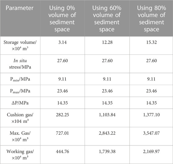
TABLE 3. Estimation of the gas storage capacity in well group S1‒S4 (double-vertical well).
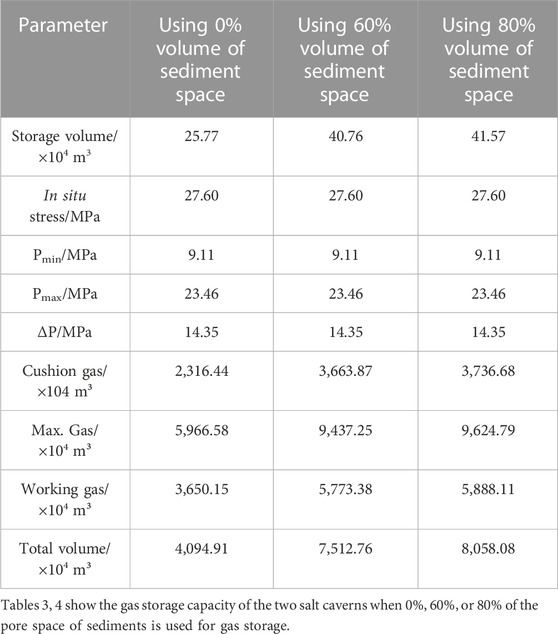
TABLE 4. Estimation of gas storage capacity in the well group S2‒S3 (two-butted well).
For the cavern of well group S1‒S4, if only the brine volume is used for gas storage, the gas storage capacity is only 444.76 × 10⁴ m3. However, if 60% or 80% of the pore space of the sediments can be used for gas storage, the gas storage capacity can be increased to 1,739.38 × 104 m3 and 2,169.97 × 104 m3, respectively. In other words, if only the brine space is used to store natural gas, the gas storage capacity will be very small, and it is impractical for gas storage. Therefore, once a certain proportion of the pore space in the sediments can be used, the gas storage capacity will be greatly increased.
Taking the working gas volume as an example, when the gas is only stored in brine space, the total working gas volume is only 4,094.91 × 104 m3. If 60% pore space of the sediments is used for gas storage, the total working gas volume can reach 7,512.76 × 104 m3. If 80% of the pore space in the sediments is used for gas storage, the total working gas capacity can reach 8,058.08 × 104 m3. Utilizing the pore space in the sediments can improve the gas storage capacity of the cavern by 0.75–1.0 times, resulting in very obvious economic benefits. Thus, the next step is to overcome the theory, tools, and technology of gas injection and brine removal in the sediments and provide theoretical guidance for the on-site implementation of gas storage in the pore space in the sediments. For example, a directional well can be drilled to connect the cavern bottom of well group S1‒S4 to the ground surface, which can be used as the brine extraction channel during gas injection. Well S2 can be repaired and used for brine extraction, while well S3 is used as the gas injection channel. In addition, the Sanshui salt mine faces many challenges in cavern construction because of the low ore grade of the salt rock and many non-salt interlayers. Therefore, using the existing caverns is a reasonable way to finish the gas storage task as soon as possible.
5 Stability simulation
5.1 Simulation model
The long-term stability of gas storage is the key factor affecting the operation safety and working life of gas storage. Thus, in this paper, the stability of salt cavern gas storage in the Sanshui salt mine during 30 years of operation is simulated. According to the regional geological data on the Sanshui salt mine, a three-dimensional (3D) geological model, as shown in Figure 6 is established. Due to the symmetry of the simulation, only a half cavern in the model is established. This geological model is 710 m long, 300 m wide, and 750 m high. In order to simplify the calculation, the overlying depth of the 900-m rock stratum is simplified as a surface load, which is approximately 21.4 MPa. A horizontal salt cavern is more feasible for gas storage; thus, this paper mainly studies the stability of horizontal cavern gas storage in this area. In our study, the maximum diameter of the horizontal cavern is 250 m, the height is 85 m, the width is 42 m, and the buried depth at the top of the cavern is approximately 1,240 m. During the gas storage period, the gas pressure in the cavern ranges from 9.11 to 23.46 MPa, while the injection-production frequency is twice a year. The gas pressure fluctuation curve of 30 years is shown in Figure 7.
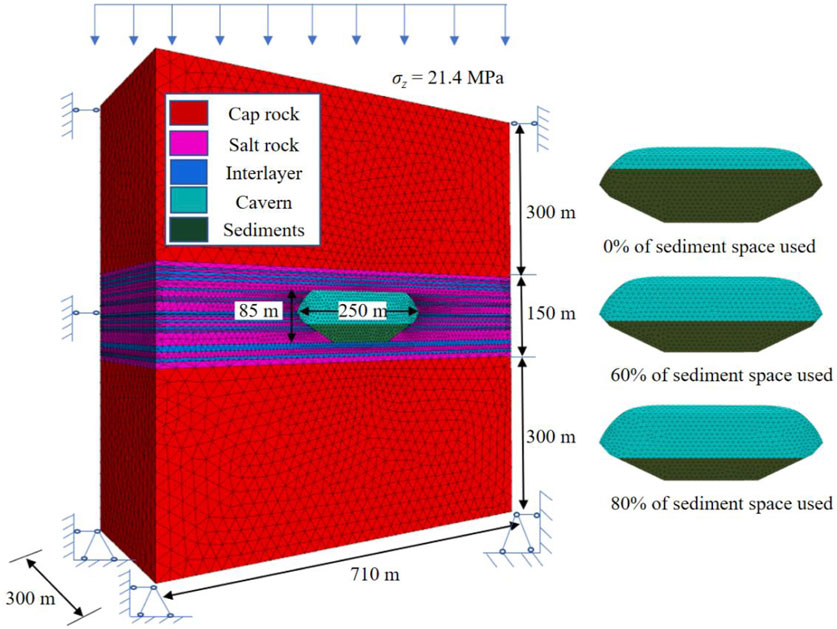
FIGURE 6. 3D geological model of the Sanshui salt mine gas storage.
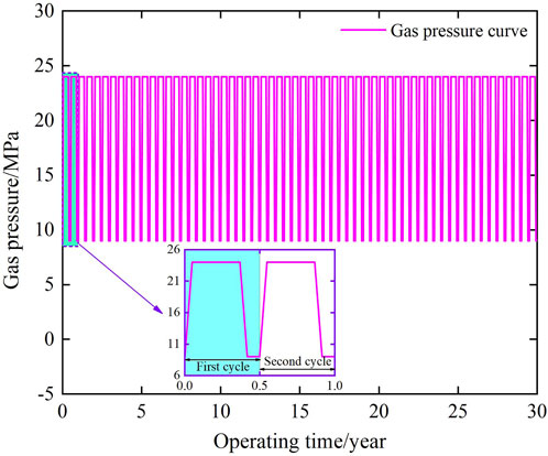
FIGURE 7. Working gas pressure in the salt cavern within 30 years.
FLAC3D software is used to simulate the stability of the horizontal cavern when different portion rates of the sediments are used for gas storage (Walsh et al., 2018; Zabolotnii et al., 2022). Moreover, the main indexes to characterize the long-term stability of the gas storage salt cavern are the volume shrinkage rate of the cavern, the volume and distribution range of plastic zones in surrounding rocks, and the displacement of key positions, such as the cavern roof or cavern waist (Liu et al., 2023b; Liu et al., 2024).
5.2 Results and analysis
(1) Volume shrinkage of the cavern
The volume shrinkage of the salt cavern is the percentage of the salt cavern volume reduction to the original salt cavern volume during operation, which is one of the main indexes to evaluate the stability of salt cavern gas storage. The smaller the volume shrinkage rate of the salt cavern, the higher the stability of gas storage. In general, when the volume shrinkage of the gas storage cavern is less than 30% after 30 years of operation, it is considered that the gas storage cavern has good stability (Zhang et al., 2022). It is worth noting that when using the pore space of sediments for gas storage, the sediments utilized for gas storage should also be regarded as a part of the cavern when calculating the volume shrinkage. After the numerical simulation, the different volume shrinkage curves within 30 years of operation are shown in Figure 8. It can be seen that with the periodic injection-production of gas, the volume shrinkage of the cavern also fluctuates periodically. With the production of gas, the internal gas pressure decreased and the volume shrinkage of the salt cavern was much larger at this time. Conversely, when the internal gas pressure increases, the volume shrinkage decreases (Katiyar and Saha, 2022).
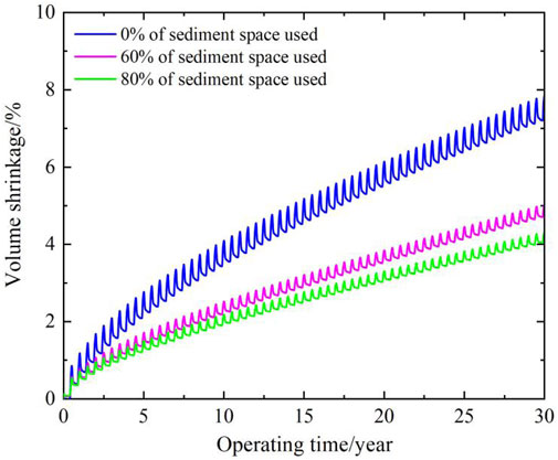
FIGURE 8. Volume shrinkage with different utilization ratios of the sediment space.
During operation, with the increase of time, the volume shrinkage of the cavern increases. Because the surrounding rock is continuously being compacted under a cyclic load, its deformation ability gradually decreases until it reaches the failure condition, which leads to the gradual slowdown of the growth rate of salt cavern volume shrinkage (Tistel et al., 2017). For caverns with different utilization rates of sediment space, with the increase of the utilization rate, the volume shrinkage shows a decreasing trend. After 30 years of operation, the volume shrinkage of the cavern without gas storage in the pore space of sediments is 7.85%, while the volume shrinkage of the cavern with 60% and 80% pore space of the sediments for gas storage is 5.03% and 4.31%, respectively. The volume shrinkage of the three storage situations is all far below the standard line of 30% within 30 years, which indicates that the horizontal salt cavern with gas storage in the pore space of sediments can meet the long-term stability requirements of gas storage.
(2) Plastic zone of the surrounding rock
As shown in Figure 9, the distribution of the plastic zone around the cavern can visually show the damage state of the surrounding rocks (Ardeshiri et al., 2015). It is found that the main type of surrounding rock failure is shear failure and the plastic zones are mainly distributed at the top and the waist of the cavern. Moreover, with the increasing utilization rate of pore space in the sediments, the distribution of plastic zones in the surrounding rocks also increases (Li et al., 2022d). Meanwhile, the increased plastic zones are mainly concentrated in the sediment area that is utilized for gas storage. The higher compressibility of gas compared to brine may account for this phenomenon as the utilization of the sediment pore space for gas storage significantly diminishes the supportive effect on the surrounding rock, thereby exacerbating rock damage.
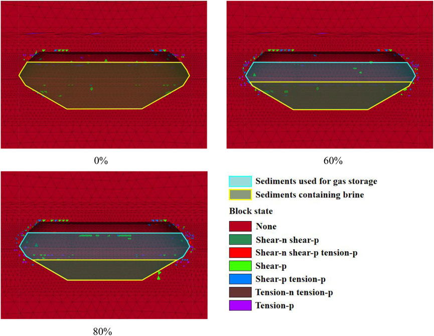
FIGURE 9. Distribution of the plastic zone around the cavern.
Additionally, the volume changes of the plastic zones of the surrounding rock are recorded. As shown in Figure 10A, when the gas pressure is low, the volume of the plastic zone is larger, which is about 1.1–1.5 times that of the peak gas pressure, indicating that it is more dangerous to operate the gas storage at a low gas pressure. Simultaneously, as the utilization rate of pore space in the sediments increases, there is a substantial augmentation in the volume of plastic zones within the surrounding rock. In addition, the plastic zones have a volume of 2.47 × 10⁴ m3 when no gas is stored in the sediments, 4.38 × 10⁴ m3 when the pore space utilization rate of sediments reaches 60%, and 4.72 × 10⁴ m3 when the pore space utilization rate of sediments reaches 80%. It is worth noting that with the increase in the pore space utilization rate of sediments, the storage volume of the cavern available for gas storage also increases. Furthermore, the change in the volume ratio of the plastic zones to the initial cavern volume under different pore space utilization rates of sediments is also analyzed, as shown in Figure 10B. It can be found that with the increase in pore space utilization of sediments, the volume ratio of the plastic zones decreases. This result shows that although the volume of the plastic zone of the surrounding rock increases, the volume ratio of the plastic zones decreases after the pore space of sediments is used for gas storage. Accordingly, when injecting and producing the same amount of gas, the plastic damage of the cavern will be smaller and the cavern stability will be better.
(3) Displacement of the surrounding rock
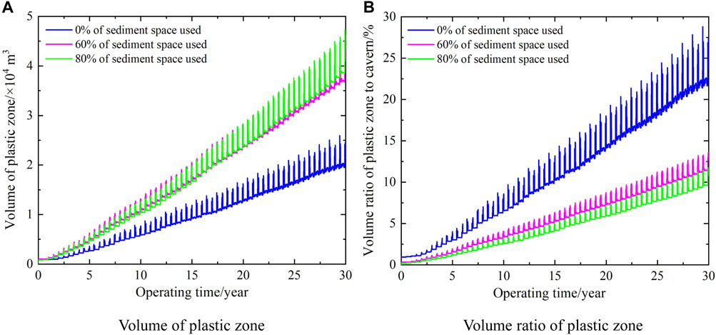
FIGURE 10. Volume change curve of the plastic zone.
Displacement of the surrounding rock can directly show the deformation of the surrounding rock and indirectly display the stability of the surrounding rock (Zareifard, 2020). The displacements of key points of a cavern within 30 years of operation, such as the central point of the cavern roof and the waist point of the cavern at the largest horizontal diameter, are recorded. Where the displacement direction of the cavern roof is vertically downward and the waist of the cavern is horizontally inward, both of them move to the cavern, indicating that the cavern is shrinking inward. As shown in Figure 11, when the pore space utilization rates of sediments increase from 0% to 80%, the displacement of the surrounding rock exhibits an increasing trend. At different positions of the cavern, the displacement of the roof of the cavern increased from 0.48 to 0.58 m, while the displacement of the cavern waist increased from 0.11 to 0.56 m. The displacement of the cavern waist point increased more than 4 times after the sediment pore space was used for gas storage. This result demonstrates that when the pore space of sediments is used for gas storage, the supporting effect of sediments on the surrounding rock is greatly reduced. Fortunately, on the whole, the displacement of the surrounding rock of the gas storage is very small, and the displacement of the roof of the cavern and waist of the cavern does not exceed 0.6 m, which is approximately 1.5% of the minimum diameter of the cavern. Therefore, the storage cavern is still considered to be stable.
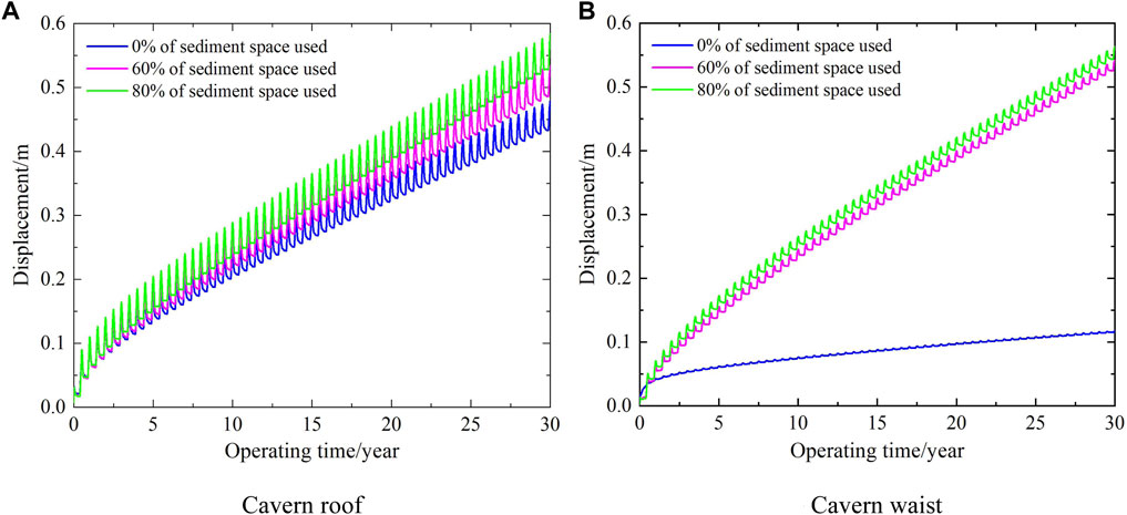
FIGURE 11. Displacement of key points of the surrounding rock.
In summary, comprehensive evaluation and comparison were conducted on the stability of sediments under different pore utilization rates. Herein, the numerical results indicate that utilizing the porosity of sediments can not only increase the gas storage capacity but also improve the stability of salt caverns. Moreover, as the utilization rate of sediment pores increases, the volume loss rate of the salt cavern and the plastic zone decreases. Although the displacement of key points has increased, the overall displacement of the cavern is small and can still be considered stable.
6 Conclusion
In this paper, the feasibility of solution mining and gas storage in the caverns of the Sanshui salt mine is evaluated. Based on the field production data, the construction process of salt caverns is numerically simulated, revealing characteristics such as the shape and size of the existing salt caverns in this mining area. The analysis includes the gas storage capacity of the salt caverns in this area, as well as an evaluation of their long-term stability. The conclusions are as follows:
(1) Based on the analysis of the basic information, such as the structure, composition, and solubility of the salt layer in the Huanghua block of the Sanshui salt mine in Guangdong province, it is considered that the exploitable salt layers in this block are the No.1‒No.7 salt layers. There are many interlayers, and the thickness of the salt layers is small; thus, the cavern construction faces great challenges. The most prominent problem is that the brine space formed in cavern construction is very small, and most of the cavern space is occupied by sediments.
(2) The solution mining processes of the well group S1‒S4 and well group S2‒S3 in the Sanshui salt mine are simulated and analyzed using the self-developed cavern-building simulation program. Details of the shape, volume, effective gas storage volume, and sediments volume of the salt cavern are obtained. For these two well groups, one vertical cavern and one horizontal cavern are simulated, and their brine space volumes are 3.41 × 10⁴ m3 and 25.77 × 10⁴ m3, respectively. Both caverns are occupied by a lot of sediments, and the sediment volumes are 33.85 × 10⁴ m3 and 52.67 × 10⁴ m3, respectively, among which the volumes of the pore space of the sediments in each cavern are 15.23 × 10⁴ m3 and 19.75 × 10⁴ m3, respectively.
(3) It is estimated that, if only the clean brine space is used, the total working gas volume is only 4,094.91 × 104 m3. If 60–80% pore space volume of the sediments is used for gas storage, the total working gas volume will reach 7,512.76 × 104–8,058.08 × 104 m3. It is estimated that the gas storage volume can increase by 0.75–1 times by making full use of the pore space of the sediments, and the economic benefits will be obvious. Accordingly, in the future plans, we should strengthen the research on gas storage in the pore space of the sediments. First, we will conduct progressive conventional rock (sediment) mechanical experiments. Subsequently, we will extensively examine the impact of the sediment content, formation depth, and temperature on cavern stability. Lastly, we aim to systematically investigate the feasibility and economic viability of utilizing sediment space in salt caverns for natural gas/compressed air/hydrogen/carbon dioxide storage.
(4) The long-term stability of the gas storage salt cavern under different utilization rates of pore space of the sediments is simulated. The simulation results show that with the increase in the sediment utilization rate from 0% to 80%, the volume shrinkage of the cavern decreases from 7.85% to 4.31%, and the distribution range and volume of the plastic zone in the surrounding rock and the displacement of cavern key points increase. Further research found that these stability evaluation indexes are all within the safe range allowed by gas storage. In addition, it is proved that the salt cavern involving gas storage in the pore space of sediments still has good stability, high economy, and huge development potential.
Data availability statement
The original contributions presented in the study are included in the article/Supplementary Material; further inquiries can be directed to the corresponding authors.
Author contributions
WY: funding acquisition, investigation, project administration, resources, and writing–original draft. QL: conceptualization, data curation, methodology, software, and writing–review and editing. XZ: conceptualization, data curation, methodology, and writing–original draft. WL: conceptualization, data curation, methodology, software, and writing–review and editing. JD: conceptualization, data curation, formal analysis, methodology, software, validation, and writing–original draft.
Funding
The author(s) declare financial support was received for the research, authorship, and/or publication of this article. This paper is supported by the funds of the Graduate Research and Innovation Foundation of Chongqing, China (grant no.CYB20023), the National Natural Science Foundation of China (52074066), and the Chongqing Talent Project (cstc2022ycjh-bgzxm0035).
Conflict of interest
Authors WY and XZ were employed by SINOPEC Research Institute of Petroleum Engineering Co., Ltd.
The remaining authors declare that the research was conducted in the absence of any commercial or financial relationships that could be construed as a potential conflict of interest.
Publisher’s note
All claims expressed in this article are solely those of the authors and do not necessarily represent those of their affiliated organizations, or those of the publisher, the editors, and the reviewers. Any product that may be evaluated in this article, or claim that may be made by its manufacturer, is not guaranteed or endorsed by the publisher.
References
Alms, K., Ahrens, B., Graf, M., and Nehler, M. (2023). Linking geological and infrastructural requirements for large-scale underground hydrogen storage in Germany. Front. Energy Res. 11, 1‒17. doi:10.3389/fenrg.2023.1172003
Ardeshiri, L. S., Yazdani, M., and Langroudi, A. A. (2015). Control of fault lay-out on seismic design of large underground caverns. Tunn. Undergr. Sp. Tech. 50, 305‒316. doi:10.1016/j.tust.2015.07.002
Chuvilin, E., Grebenkin, S., and Zhmaev, M. (2021). Gas permeability of sandy sediments: effects of phase changes in pore ice and gas hydrates. Energy fuels. 35, 7874–7882. doi:10.1021/acs.energyfuels.1c00366
Evans, B., and Brooks, E. (2021). Analysts expect US working gas in storage to increase 37 Bcf: survey. Platts Energy Trader 2021, 1–15.
Fu, J., Wang, X., Gu, Y. X., and Zhang, S. Y. (2018). Research on engineering solutions for presalt formation development and depleted salt cavern utilization in China and Middle Asia. SPE Annu. Casp. Tech. Conf. Exhib., 1–12.
Jong, C. D. (2015). Gas storage valuation and optimization. J. Nat. Gas. Sci. Eng. 24, 365–378. doi:10.1016/j.jngse.2015.03.029
Katiyar, N., and Saha, S. K. (2022). Study of shrinkage effect of aluminium based binary alloys as phase change materials for latent heat thermal energy storage applications. J. Energy Storage 47, 103587. doi:10.1016/j.est.2021.103587
Li, D. P., Liu, W., Jiang, D. Y., Chen, J., Fan, J. Y., and Qiao, W. B. (2022a). Quantitative investigation on the stability of salt cavity gas storage with multiple interlayers above the cavity roof. J. Energy Storage 44, 103298. doi:10.1016/j.est.2021.103298
Li, J. C., Wan, J. F., Liu, H. M., Jurado, M. J., He, Y. X., Yuan, G. J., et al. (2022b). Stability analysis of a typical salt cavern gas storage in the jintan area of China. Energies 15, 4167. doi:10.3390/en15114167
Li, J. L., Tang, Y., Shi, X. L., Xu, W. J., and Yang, C. H. (2019). Modeling the construction of energy storage salt caverns in bedded salt. Applied Energy 255, 113866. doi:10.1016/j.apenergy.2019.113866
Li, M., Wu, P., Zhou, S. S., Zhang, L. X., Yang, L., Li, Y. H., et al. (2021a). Permeability analysis of hydrate-bearing sediments during the hydrate formation process. Energy fuels. 35 (23), 19606–19613. doi:10.1021/acs.energyfuels.1c02913
Li, P., Li, Y. P., Shi, X. L., Zhao, K., Liang, X. P., Ma, H. L., et al. (2022c). Compaction and restraining effects of insoluble sediments in underground energy storage salt caverns. Energy 249, 123752. doi:10.1016/j.energy.2022.123752
Li, P., Li, Y. P., Shi, X. L., Zhao, K., Liu, X., Ma, H. L., et al. (2021b). Prediction method for calculating the porosity of insoluble sediments for salt cavern gas storage applications. Energy 221, 119815. doi:10.1016/j.energy.2021.119815
Li, Q. H., Song, D. Q., Yuan, C. M., and Nie, W. (2022d). An image recognition method for the deformation area of open-pit rock slopes under variable rainfall. Measurement 188, 110544. doi:10.1016/j.measurement.2021.110544
Li, X. S., Li, Q. H., Hu, Y. J., Chen, Q. S., Peng, J., Xie, Y. L., et al. (2022e). Study on three-dimensional dynamic stability of open-pit high slope under blasting vibration. Lithosphere 2021, 1–17. doi:10.2113/2022/6426550
Li, X. S., Li, Q. H., Wang, Y. M., Liu, W., Hou, D., Zheng, W. B., et al. (2023). Experimental study on instability mechanism and critical intensity of rainfall of high-steep rock slopes under unsaturated conditions. Int. J. Min. Sci. Techno. 33, 1‒19. doi:10.1016/j.ijmst.2023.07.009
Liu, W., Chen, J., Jiang, D. Y., Shi, X. L., Li, Y. P., Daemen, J. J. K., et al. (2016). Tightness and suitability evaluation of abandoned salt caverns served as hydrocarbon energies storage under adverse geological conditions (AGC). Applied Energy 178, 703‒720. doi:10.1016/j.apenergy.2016.06.086
Liu, W., Zhang, Z. X., Chen, J., Fan, J. Y., Jiang, D. Y., Daemen, J. J. K., et al. (2019). Physical simulation of construction and control of two butted-well horizontal cavern energy storage using large molded rock salt specimens. Energy 185, 682–694. doi:10.1016/j.energy.2019.07.014
Liu, W., Zhang, X., Fan, J. Y., Wang, L., and Li, Y. P. (2020). Evaluation of potential for salt cavern gas storage and integration of brine extraction: cavern Utilization, Yangtze River Delta Region. Nat. Resour. Res. 29, 3275–3290. doi:10.1007/s11053-020-09640-4
Liu, X., Shi, X. L., Li, Y. P., Li, P., Zhao, K., Ma, H. L., et al. (2021). Maximum gas production rate for salt cavern gas storages. Energy 234, 121211. doi:10.1016/j.energy.2021.121211
Liu, W., Li, Q. H., Yang, C. H., Shi, X. L., Wan, J. F., Jurado, M. J., et al. (2023a). The role of underground salt caverns for large-scale energy storage: a review and prospects. Energy Storage Mater, 103045. doi:10.1016/j.ensm.2023.103045
Liu, W., Duan, X. Y., Li, Q. H., Wan, J. F., Zhang, X., Fang, J., et al. (2023b). Analysis of pressure interval/injection and production frequently on stability of large-scale supercritical CO2 storage in salt caverns. J. Clean. Prod. 139731. doi:10.1016/j.jclepro.2023.139731
Liu, W., Du, J. W., Li, Q. H., Shi, X. L., Chen, J., Yi, W. K., et al. (2024). Feasibility analysis on the utilization of TWH-caverns with sediment space for gas storage: A case study of Sanshui salt mine. J. Energy Storage 75, 109576. doi:10.1016/j.est.2023.109576
Marbun, B. T. H., Ridwan, R. H., Nugraha, H. S., Sinaga, S. Z., and Purbantanu, B. A. (2021). Review of directional drilling design and operation of geothermal wells in Indonesia. Renewable Energy 176, 135–152. doi:10.1016/j.renene.2021.05.078
Mcglade, C., Speirs, J., and Sorrell, S. (2013). Unconventional gas - a review of regional and global resource estimates. Energy 55, 571–584. doi:10.1016/j.energy.2013.01.048
Pons, M. J., Franchini, M., Rainoldi, A. L., Giusiano, A., Cesaretti, N. N., Montagna, A. O., et al. (2021). Base metal mobility linked to brine and hydrocarbon migration at the Huincul High in the Neuquen Basin, Argentina: implications for the formation of sediment-hosted base metal deposits. J. Geochem. Explor. 226, 106778. doi:10.1016/j.gexplo.2021.106778
Ren, S., Wu, J. X., Chen, J., Jiang, D. Y., Wen, Y. J., and Qiu, H. F. (2014). Development of simulation software for layered salt rock and verification of its practicality. Rock Soil Mech. 35, 2725‒2730.
Schwab, L., Prinsen, L., Nowack, G., Popp, D., Noll, M., Vogt, C., et al. (2023). Sulfate reduction and homoacetogenesis at various hypersaline conditions: implications for H-2 underground gas storage. Front. Energy Res. 11, 1‒12. doi:10.3389/fenrg.2023.1125619
Sobolik, S. R., and Lord, A. S. (2015). “Operation, maintenance, and monitoring of large-diameter caverns in oil storage facilities in domal salt,” in Mechanical behaviour of salt VIII–roberts, mellegard and hansen (London: Taylor and Francis Group), 1–13.
Tistel, J., Grimstad, G., and Eiksund, G. (2017). Testing and modeling of cyclically loaded rock anchors. J. Rock Mech. Geotech. 9, 1010–1030. doi:10.1016/j.jrmge.2017.07.005
Van, T. V. K., Hendriks, D., Marsman, A., Nepveu, M., Groenenberg, R., Wildenborg, T., et al. (2014). Bow-tie risk assessment combining causes and effects applied to gas oil storage in an abandoned salt cavern. Eng. Geol. 168, 149‒166. doi:10.1016/j.enggeo.2013.11.002
Walsh, R., Nasir, O., Calder, N., Sterling, S., and Avis, J. (2018). Combining TOUGH2 and FLAC3D to solve problems in underground gas storage. Transp. Porous Med. 123, 501–519. doi:10.1007/s11242-017-0976-z
Wan, J. F., Peng, T. J., Yuan, G. J., Ban, F. S., Jurado, M. J., and Xia, Y. (2020). Influence of tubing/oil-blanket lifting on construction and geometries of two-well-horizontal salt caverns. Tunn. Undergr. Sp. Tech. 108, 103688. doi:10.1016/j.tust.2020.103688
Wang, J. F., An, G. Y., Shan, B. D., Wang, W. Q., Jia, J. C., Wang, T. T., et al. (2021). Parameter optimization of solution mining under nitrogen for the construction of a gas storage salt cavern. J. Nat. Gas. Sci. Eng. 91, 103954. doi:10.1016/j.jngse.2021.103954
Wu, D., Geng, Y., and Pan, H. (2021). Whether natural gas consumption bring double dividends of economic growth and carbon dioxide emissions reduction in China? Renew. Sust. Energ. Rev. 137, 110635. doi:10.1016/j.rser.2020.110635
Yang, C. H., Li, Y. P., and Chen, F. (2009). Bedded salt rock mechanics and engineering. Beijing: Science Press, 165–181.
Yang, C. H., Wang, T. T., and Chen, H. S. (2022). Theoretical and technological challenges of deep underground energy storage in China. Engineering 25, 168–181. doi:10.1016/j.eng.2022.06.021
Yang, C. H., Wang, T. T., Li, Y. P., Yang, H. J., Li, J. J., Qu, D. A., et al. (2015). Feasibility analysis of using abandoned salt caverns for large-scale underground energy storage in China. Applied Energy 137, 467–481. doi:10.1016/j.apenergy.2014.07.048
You, L. J., Meng, S., Kang, Y. L., Chen, M. J., and Shao, J. X. (2021). Formation damage mechanism and protection measures for gas field storage. Petroleum Reserv. Eval. Dev. 11, 395‒403.
Yuan, C. M., Li, Q. H., Nie, W., and Ye, C. Y. (2023). A depth information-based method to enhance rainfall-induced landslide deformation area identification. Measurement 219, 113288. doi:10.1016/j.measurement.2023.113288
Zabolotnii, E., Morgenstern, N. R., and Wilson, G. W. (2022). Mechanism of failure of the mount polley tailings storage facility. Can. Geotech. J. 59, 1503–1518. doi:10.1139/cgj-2021-0036
Zárante, P. H. B., and Sodré, J. R. (2009). Evaluating carbon emissions reduction by use of natural gas as engine fuel. J. Nat. Gas. Sci. Eng. 1, 216‒220. doi:10.1016/j.jngse.2009.11.002
Zareifard, M. R. (2020). Ground reaction curve for deep circular tunnels in strain-softening mohr-coulomb rock masses considering the damaged zone. Int. J. Geomech. 20, 1‒19. doi:10.1061/(ASCE)GM.1943-5622.0001822
Zhang, Z. X., Liu, W., Guo, Q., Duan, X. Y., Li, Y. P., and Wang, T. T. (2022). Tightness evaluation and countermeasures for hydrogen storage salt cavern contains various lithological interlayers. J. Energy Storage 50, 104454. doi:10.1016/j.est.2022.104454
Zheng, Y. A., Luo, J., Chen, J. B., Chen, Z. Y., and Shang, P. P. (2023). Natural gas spot price prediction research under the background of Russia-Ukraine conflict-based on FS-GA-SVR hybrid model. J. Environ. Manage. 344, 118446. doi:10.1016/j.jenvman.2023.118446
Zhou, H. W., Wang, C. P., Han, B. B., and Duan, Z. Q. (2011). A creep constitutive model for salt rock based on fractional derivatives. Int. J. Rock Mech. Min. 48, 116–121. doi:10.1016/j.ijrmms.2010.11.004
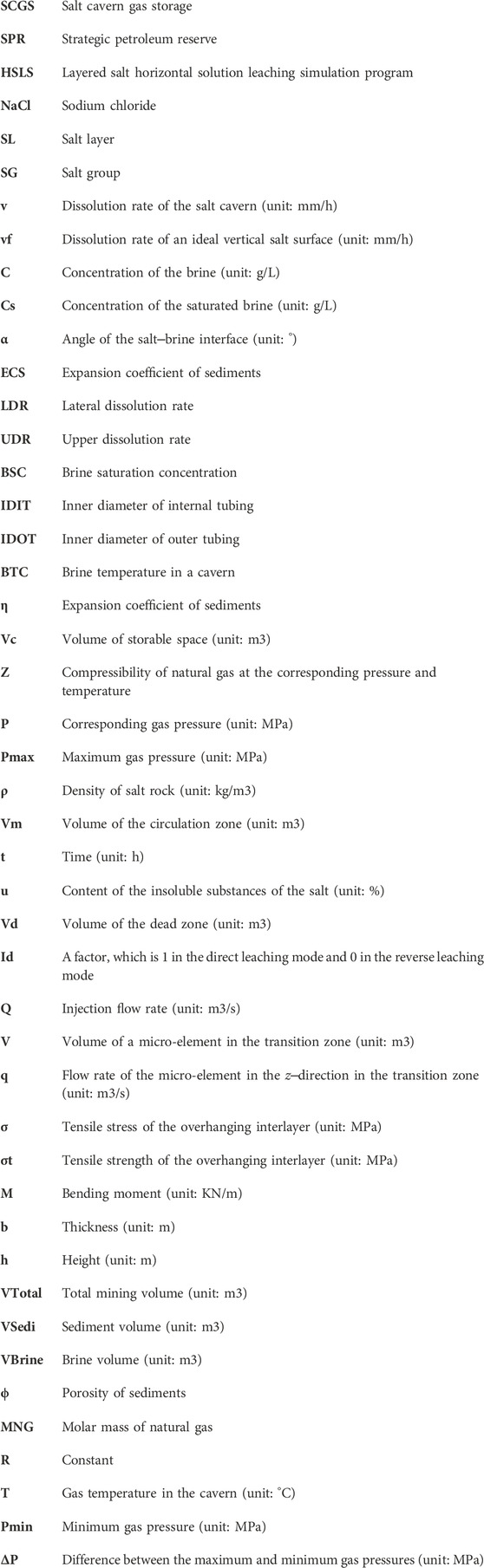
Nomenclature
Keywords: Sanshui salt mine, gas storage, solution mining, working gas volume, sediment voids, long-term stability
Citation: Yi W, Li Q, Zhao X, Liu W and Du J (2023) Feasibility assessment of solution mining and gas storage in salt caverns: a case study of the Sanshui salt mine. Front. Energy Res. 11:1301765. doi: 10.3389/fenrg.2023.1301765
Received: 25 September 2023; Accepted: 14 November 2023;
Published: 30 November 2023.
Edited by:
Mohsen Izadi, Lorestan University, IranReviewed by:
Kai Zhao, The University of Hong Kong, Hong Kong SAR, ChinaAhmad Hajjar, Vinh University, Vietnam
Copyright © 2023 Yi, Li, Zhao, Liu and Du. This is an open-access article distributed under the terms of the Creative Commons Attribution License (CC BY). The use, distribution or reproduction in other forums is permitted, provided the original author(s) and the copyright owner(s) are credited and that the original publication in this journal is cited, in accordance with accepted academic practice. No use, distribution or reproduction is permitted which does not comply with these terms.
*Correspondence: Qihang Li, cWloYW5nbGkwMzI1QDEyNi5jb20=; Wei Liu, d2hyc21saXV3ZWlAMTI2LmNvbQ==