 Xu Yang
 Zhicheng Liu
 Jin Zhu
 Pei Liu
 Tongzhen Wei2
- 1Wuhan University of Technology, Wuhan, China
- 2Institute of Electrical Engineering, Chinese Academy of Sciences, Beijing, China
The research domain about the selection and design methodology of battery topology structures for energy storage systems, grounded in practical application scenarios, remains significantly underexplored. Furthermore, a substantial gap exists in the current state of research, where the majority of studies lack a comprehensive analysis of losses and reliability associated with reconfigurable battery topology structures. This paper quantitatively analyzes existing MOSFET-based topologies from three key dimensions: losses, costs, and reliability. The study aims to discern the impact of different topology structures and energy storage systems with redundant units on these three dimensions. Subsequently, while ensuring the adaptability of the topology structure, we propose a novel reconfigurable battery system topology suitable for DC microgrids, accompanied by its corresponding control strategy. Through comparative analysis with three typical topology structures, this topology structure has been validated to exhibit certain advantages in terms of losses, reliability, and costs. Lastly, the feasibility of the introduced topology structure is demonstrated through simulation using MATLAB/Simulink. Simulation results indicate that the proposed topology structure not only provides precise control of charge and discharge currents but also demonstrates excellent battery balancing capabilities.
1 Introduction
In the era of the energy internet, the utilization of large-scale Battery Energy Storage Systems (BESS) is experiencing a notable upsurge in prevalence. Correspondingly, the associated concerns regarding the efficiency and safety aspects of BESS have garnered considerable attention within the research sphere (Chen et al., 2022). In the operational context of real-world battery systems, safety issues such as internal short circuits and thermal runaway are prone to activation due to the existing constraints associated with the current state of development in electrical, thermal, and safety management system technologies (Wen et al., 2012; Chen et al., 2018; Yang et al., 2020). Consequently, the widespread adoption of battery energy storage systems faces certain limitations concerning their safety and reliability.
Conventional battery energy storage systems frequently employ a fixed series and parallel configuration to fulfill intricate utilization demands and attain elevated voltage and power levels. Nevertheless, owing to inherent disparities among individual batteries, the challenge of battery inconsistency frequently arises within battery energy storage systems. This can potentially give rise to issues like overcharging, over-discharging, and the accumulation of thermal effects within batteries (Han et al., 2019). In order to tackle the challenges inherent in conventional setups, the exploration of reconfigurable battery network technology within battery energy storage systems has captured noteworthy interest among researchers. (Ci et al., 2016; He et al., 2018; Lin et al., 2018; Yang et al., 2022; Tashakor et al., 2023). A digitally controlled energy exchange system employing a reconfigurable battery network structure can dynamically adjust the switch array to achieve various relationships, including series, parallel, and hybrid combinations. (Ci et al., 2007). this structure allows for the connection of batteries with lower State of Charge (SOC) during the charging phase and batteries with higher SOC during discharging, presenting a practical solution to address battery imbalances. Moreover, in cases of battery anomalies such as short circuits, the system swiftly isolates the problematic battery. This action serves to mitigate the underutilization attributed to the “bucket effect” phenomenon and averts severe incidents like thermal runaway. As a result, this approach not only extends battery lifespan but also elevates operational safety, thereby fortifying overall system reliability. While traditional battery topologies exhibit lower control complexity compared to dynamically reconfigurable battery topologies, they often lack flexibility and adaptability. A comparison of some key characteristics is presented in Table 1.
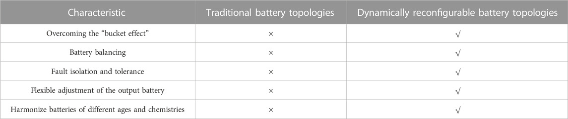
TABLE 1. Comparison of the characteristics of traditional battery topologies and dynamically reconfigurable battery topologies.
Currently, existing battery topology structures can be categorized into two types: series-parallel and parallel-series configurations. Each of these structures presents distinct advantages and drawbacks, along with corresponding suitability for specific application scenarios. The series-parallel configuration, by connecting energy storage units in series, facilitates achieving higher output voltages, making it suitable for applications requiring elevated voltage levels. An advantage lies in its ability to balance the charge and discharge among energy storage units through series connections, thereby mitigating issues of cell mismatch. However, series strings comprising cells with lower voltages can affect the system’s dynamic performance due to short-circuiting and cell degradation concerns. Additionally, variations between battery strings during the charge and discharge phases can lead to imbalanced currents among the serially connected modules. For the parallel-series configuration, achieved by connecting energy storage units in parallel, a higher output current can be obtained, making it suitable for applications requiring elevated current levels. One advantage is the potential for a certain degree of “self-balancing” among batteries connected in parallel, where charge can flow from higher-voltage batteries to lower-voltage ones. However, during the battery series operation, this phenomenon can result in continuous charging and discharging of the batteries, leading to energy waste and heat generation, ultimately shortening the battery’s operational lifespan. Furthermore, due to the parallel connection, if one energy storage unit fails, the other units can continue to operate normally, thus enhancing the system’s reliability. This configuration also presents certain drawbacks. For instance, significant currents may flow out from batteries with lower parallel resistance, accelerating their deterioration. Moreover, if the State of Charge (SOC) of one parallel-connected battery approaches zero, it could potentially lead to a short circuit within the same group of batteries. In summary, the series-parallel configuration is suitable for scenarios demanding high-voltage output and enhanced scalability. On the other hand, the parallel-series configuration is well-suited for applications requiring high-current output and elevated reliability. In reference (Moo et al., 2008), the battery configuration of a series-parallel connection demonstrates automated charge balancing, enhancing the flexibility of battery capacity provisioning in the system. However, this configuration incurs elevated installation costs and exhibits relatively lower overall power conversion efficiency. In reference (Kim et al., 2012a), a battery switching circuit topology for an
References (Manenti et al., 2011; Kim et al., 2011; Kim et al., 2012b; He et al., 2016; Quraan et al., 2017; Gan et al., 2019; Tashakor et al., 2021) have equipped individual battery cells within a series configuration with two switches, allowing for the determination of whether the specific battery cell is operational or not. This structure enhancement fault tolerance and safety. References (Gunlu, 2017; He et al., 2017; Kersten et al., 2020; Kuder et al., 2020; Zheng et al., 2021) propose utilizing three switches to facilitate four distinct operational modes for batteries: series, parallel, bypass, and a hybrid mode (series-parallel-bypass). This configuration enables swift isolation of faulty battery cells, thereby enhancing the system’s fault tolerance capabilities. While enhancing operational efficiency, it also possesses flexible scalability attributes. References (Ci et al., 2007; Ci et al., 2012; He et al., 2013) have implemented a configuration with four switches for each battery cell to alter the connectivity, thereby increasing battery operational time. Moreover, reconfigurable battery arrays exhibit improved performance under low voltage and low discharge current conditions. In reference (Kim and Shin, 2009), each battery is equipped with six switches to facilitate the adaptable operation of the battery system. While this configuration enhances the system’s fault tolerance capabilities, the substantial number of switches in practical implementation notably compromises system reliability and increases its volume. Several typical topologies in energy storage systems are shown in Figure 1.
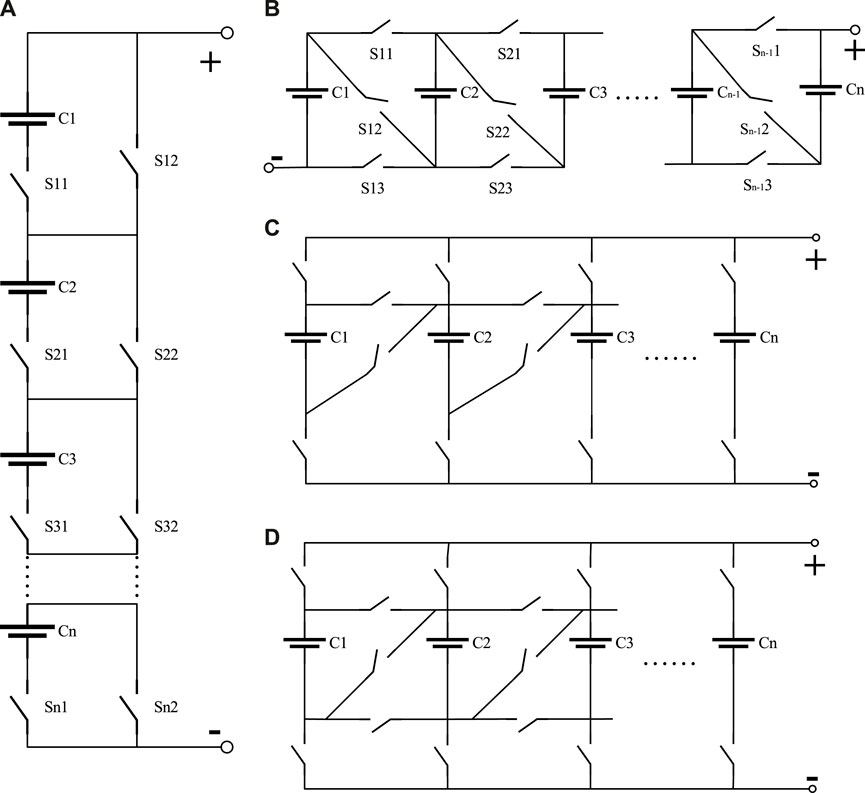
FIGURE 1. Several typical topology structures. (A) Two switches. (B) Three switches. (C) Four switches. (D) Five switches.
The majority of the aforementioned literature either considers ideal switch configurations or relies on mechanical relays for the topology of battery energy storage systems. However, mechanical relays exhibit arcing phenomena when interrupting high-current circuits, leading to a reduced lifespan of relay contacts. As a result, low-cost and high-efficiency power MOSFETs have garnered significant attention from researchers as potential switches in unit-switching circuits. Power MOSFETs not only facilitate bidirectional current conduction but also exhibit minimal resistance when in the on-state, rendering conduction losses negligible. In the battery topology configurations of energy storage systems, the switching frequency of the switches is low, often necessitating a significant amount of time to modify the state of a battery switch (Kim et al., 2012a). Therefore, employing MOSFETs can substantially reduce conduction losses within the circuit. The performance comparison between mechanical switches and MOSFETs is illustrated in Table 2. References (Kim et al., 2011; Kim et al., 2012a; Quraan et al., 2017) equip each battery cell with two MOSFETs, resulting in relatively straightforward control. However, current flows through the parallel diodes, leading to increased losses. Additionally, this topology cannot fully disconnect the main branch. References (Gunlu, 2017; Kuder et al., 2020) utilize three MOSFETs to control the connection and disconnection of individual battery cells. This configuration empowers battery units to adaptively alter their connection mode based on varying loads. Moreover, with three MOSFETs per module, the economy of the system is ensured while ensuring secure and reliable operation. In Reference (Manenti et al., 2011), four MOSFETs are employed. The N-channel MOSFETs ensure low conduction losses during conduction, while the P-channel MOSFETs guarantee the ability to withstand higher currents when bypassing the battery. Compared to the topology with two MOSFETs, this configuration enables a complete disconnection of individual battery cells. However, for higher-power loads, the complexity of the layout notably increases, which results in poorer economic feasibility.
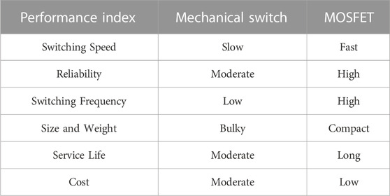
TABLE 2. Comparison between mechanical switchs and MOSFETs
Generally speaking, a structure involving two MOSFETs is relatively straightforward, requiring minimal complexity in control. This configuration is suitable for small-scale energy storage systems that primarily necessitate simple series or parallel connections without extensive topological variations, such as residential energy storage systems. A configuration involving three MOSFETs enables more intricate topological arrangements, such as series-parallel hybrid structures. This configuration is suitable for scenarios requiring multiple operational modes to meet flexibility demands or for medium-sized energy storage systems, as seen in industrial applications. Configurations employing four or more MOSFETs are well-suited for large-scale energy storage systems requiring elevated flexibility and intricate topological arrangements, or scenarios demanding advanced battery management and optimization. For instance, in substantial energy storage systems, the need might arise for simultaneous parallel and series connections of multiple battery units to meet specific power and energy requirements. However, within specific application contexts, a higher number of MOSFETs entail increased complexity in control and management, elevated costs, greater power consumption, and a heightened probability of failures. Typically, the selection and design of energy storage system topologies involve considerations of various factors, including performance requirements, cost, reliability, safety, efficiency, system complexity, flexibility, and capacity adjustment capabilities. In applications such as satellites and spacecraft, energy storage systems are challenging to maintain. Therefore, the selection and design of battery topologies prioritize reliability and safety over complexity, cost, flexibility, and other factors. In power grid applications, there are higher requirements for performance, cost, efficiency, and safety, with relatively lower demands on reliability and flexibility. Therefore, selecting the appropriate topology structure in practical applications requires a careful consideration of these factors to achieve the best system performance while meeting economic requirements.
Currently, research in the field of selecting and designing battery topology structures for energy storage systems based on practical application scenarios remains largely unexplored. Additionally, most energy storage system applications lack comprehensive analyses concerning the losses and reliability associated with reconfigurable battery topology structures. This paper conducts quantitative and scenario-adaptive analyses of existing reconfigurable battery topologies, presenting a topology structure suitable for direct current microgrid applications. Subsequently, the feasibility of the proposed topology structure is validated in MATLAB/Simulink. Moreover, a comparative assessment against several classical topologies is performed, demonstrating the advantages of the proposed topology in terms of losses and reliability. The main contributions of this paper can be summarized in the following three aspects.
(1) An analysis of existing MOSFET-based reconfigurable topologies is conducted from the perspectives of advantages, disadvantages, losses, reliability, and suitability for various scenarios.
(2) A reconfigurable battery topology tailored for DC microgrids is proposed. This architecture exhibits distinct advantages in terms of conduction losses, reliability, and cost-effectiveness.
(3) Corresponding control strategies for the proposed battery topology are introduced, and the feasibility of this structure is validated through simulations conducted in MATLAB/Simulink.
The remaining sections of this paper are as follows. Section Ⅱ provides a comparative analysis of losses, reliability, and costs among various MOSFET-based topology structures. In Section Ⅲ, the proposed topology structure and its accompanying control strategies are elucidated. Section Ⅳ substantiates the feasibility and advantages of the proposed topology through a case study. Lastly, Section Ⅴ encapsulates the conclusions drawn from the work presented in this paper.
2 Power consumption & reliability analysis
Losses and reliability are crucial metrics for evaluating the performance of an energy storage system. For the same application scenario, there exist various choices for selecting the topology structure. Due to the drawbacks associated with structures employing four or more MOSFETs, including complexities in control, costs, power consumption, reliability, and subsequent maintenance, this paper opts for the inclusion of classical topology structures employing 2 MOSFETs, 3 MOSFETs, and 4 MOSFETs. A comparative analysis is conducted between these structures in terms of power consumption and reliability. Several topology structures are depicted in Figure 2. As the series connection mode is a shared element among these three structures, this paper exclusively focuses on analyzing losses and reliability within the series operation mode. Furthermore, for analytical convenience, it is assumed that all scenarios consist of a series of N battery cells.
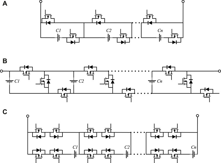
FIGURE 2. Several typical topology structures. (A) Two MOSFETs. (B) Three MOSFETs. (C) Four MOSFETs.
2.1 Loss analysis
As depicted in Figure 2A, the battery topology structure entails the deployment of one MOSFET for switch operation and an additional MOSFET for bypass functionality per battery. Furthermore, in instances where a battery string is connected into the circuit, an additional pair of MOSFETs is requisite to achieve bidirectional disconnection of the battery string. The topology structure illustrated in Figure 2B can achieve flexible battery series, parallel, and hybrid configurations using three MOSFETs. In this discussion, only the series configuration is considered, where each battery is connected in series using a single MOSFET. Figure 2C employs a scheme in which two MOSFETs function as a single switch. In the case of battery series connection, two MOSFETs are required to achieve switch operation, while the remaining two MOSFETs are tasked with bypass functionality. Assuming that the conduction loss of the MOSFET is denoted as
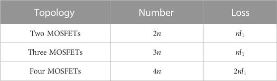
TABLE 3. MOSFET number and loss analysis of different topologies.
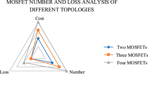
FIGURE 3. MOSFET number and loss analysis of different topologies.
2.2 Reliability analysis
In scenarios requiring the series connection of a large number of individual battery cells, the reliability of an energy storage system tends to decrease due to the “bucket effect” among batteries. However, the aforementioned topology structures, by effectively bypassing faulty battery cells without impacting system operation, can significantly enhance the system’s reliability.
Assuming that the components and system lifetimes follow an exponential distribution, the failure rate
Where

FIGURE 4. Reliability model for series configuration.
In this calculation, only the battery and MOSFET are considered. Therefore, the reliability of the energy storage system is given by:
Battery Operational Failure Rate Estimation Model:
Where
Projected Operational Failure Rate Model for Silicon Field-Effect Transistors:
Where
Taking into consideration that energy storage systems typically consist of redundant modules, the reliability assessment of an energy storage system comprises two distinct components. The first component pertains to the MOSFETs, assuming the reliability of a single MOSFET is
Hence, the reliability model with redundant battery topology is shown in Figure 5.
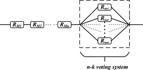
FIGURE 5. Reliability model for energy storage system with redundant units.
This study conducts a reliability analysis of the three energy storage systems depicted in Figure 2. The parameters utilized for the analysis are detailed in Table 4. Taking a scenario with 20 series-connected batteries as an example, the reliabilities for 2 MOSFETs, 3 MOSFETs, and 4 MOSFETs are 0.8778, 0.8725, and 0.8673, respectively. With the inclusion of one redundant unit, the reliabilities become 0.9808, 0.9746, and 0.9685, and with two redundant units, they become 0.9866, 0.9801, and 0.9737. As the number of series-connected batteries increases to 60, the reliabilities become 0.6763, 0.6643, and 0.6524, respectively. From this, it can be deduced that as the number of series-connected batteries increases, the reliability of the energy storage system decreases. Furthermore, when equating the number of batteries in different topology structures, the system’s reliability degrades as more MOSFETs are utilized. In energy storage systems, adding redundant units is a common practice, serving to enhance fault tolerance, capacity expansion capability, and charge balancing capacity. The addition of a single battery cell in an energy storage system significantly improves system reliability. However, as the number of redundant cells increases, the improvement in system reliability becomes marginal. Figure 6 provides a detailed insight into the impact of different topology structures, varying numbers of series-connected batteries, and the presence of redundant batteries on reliability. Nevertheless, in real-world engineering applications, adding redundant units also increases system size, weight, and additional costs. Hence, selecting the appropriate number of redundant units based on practical application scenarios is of paramount importance.
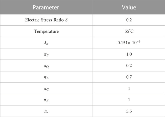
TABLE 4. Work failure rate calculation parameters.
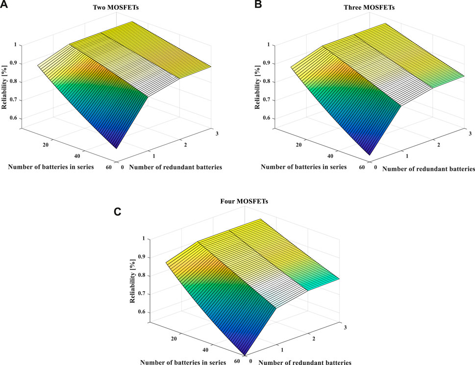
FIGURE 6. Comparison of reliability among different topology structures. (A) Two MOSFETs. (B) Three MOSFETs. (C) Four MOSFETs.
3 The proposed topology
This paper takes into account the current research gap in the selection and design methodology of battery topology structures for energy storage systems in practical application scenarios. In conjunction with the demand for high energy conversion efficiency and reliability within real-world application contexts, a novel topology structure is proposed. As illustrated in Figure 7, the proposed configuration, exemplified with three battery modules, primarily comprises two components: the battery module and the battery switching circuit. The distinguishing feature of this topology resides in its ability to enhance energy conversion efficiency and reliability while preserving structural flexibility. Furthermore, it achieves a reduction in the quantity of MOSFETs employed within the energy storage system and alleviates the complexity of control circuits.
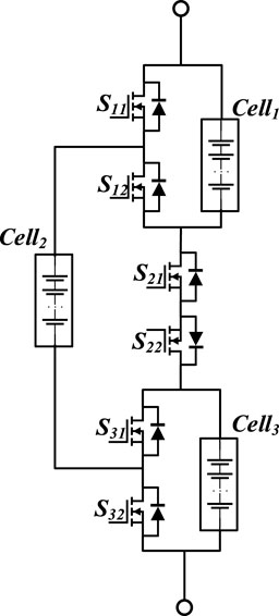
FIGURE 7. The proposed topology structure.
3.1 Switching networks
Compared to traditional mechanical switches, MOSFETs offer advantages such as faster response times, smaller form factors, enhanced reliability, lower costs, and reduced power consumption. Therefore, the proposed topology employs power MOSFETs as the switching elements within the network, capitalizing on their benefits. As illustrated in Figure 7, only 6 N-channel MOSFETs are required for the configuration of 3 battery modules. In the case of utilizing 2 battery modules for output, one battery module remains redundant. In this scenario, the redundancy among the 3 battery modules facilitates rapid balancing between them via control of the 6 MOSFETs. This approach effectively mitigates the risks of overcharging and over-discharging in battery modules, thereby enhancing their operational lifespan and utilization duration.
3.2 Working principle
Within this topology, there is the flexibility to choose between outputting a single battery module, two battery modules, or all three battery modules independently. Furthermore, a hybrid configuration of parallel connection of two modules followed by a series connection of one module is also attainable. Consequently, there are a total of seven operational modes as depicted in Figure 8.
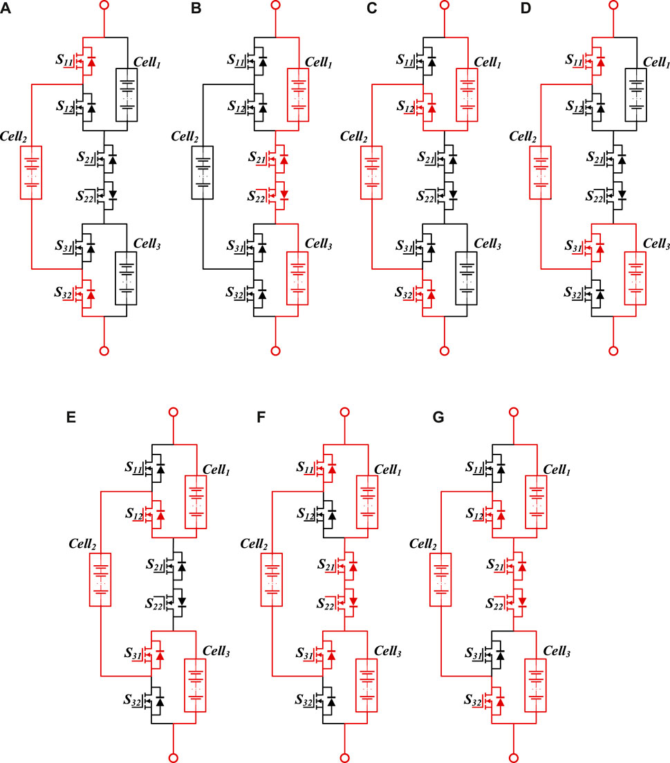
FIGURE 8. The operational principle of the topology structure. (A) When
3.3 Control strategy
The proposed topology structure in this study enables control over charging and discharging currents to accommodate diverse power requirements, thereby facilitating the realization of self-balancing capabilities for the batteries. Figure 9 illustrates the control strategy of the proposed topology structure, which is primarily divided into two components: output current control and battery balancing control. In this topology, the engagement of individual battery cells is regulated by controlling the opening and closing of MOSFETs.
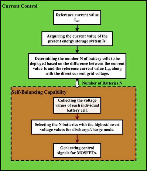
FIGURE 9. The proposed control strategy.
3.3.1 Current control
Selecting different numbers of battery cells for engagement results in varying positive and negative voltage differentials with the DC microgrid side. When dynamically changing the number of engaged battery cells, the voltage across the inductor of the energy storage system becomes the difference between the system’s output and the DC microgrid-side voltage. By comparing the collected current value with the reference current value, the number of battery cells to be engaged is determined. Subsequently, a series of positive pulse signals are employed to control the MOSFETs, thereby connecting or disconnecting the corresponding battery cells. This process stabilizes the current in proximity to the desired value.
3.3.2 Self-balancing capability
The self-balancing capability is one of the dynamic advantages of the reconfigurable battery system. If all individual battery cells exhibit similar voltages, the selection of batteries can be arbitrary. However, when significant voltage discrepancies exist among battery cells, a strategy can be employed during discharge to prioritize batteries with higher voltages and during charging to prioritize those with lower voltages. By dynamically selecting battery cells based on the desired count for engagement, the system achieves a self-balancing functionality.
4 Case study
In order to validate the feasibility of the proposed topological configuration for flexible operation, a system with three battery modules was simulated using MATLAB/Simulink. Table 5 furnishes the principal parameters of this energy storage system.

TABLE 5. Parameters of the simulated system.
4.1 Various operational modes
The capability to adjust the magnitude of the output voltage stands as a significant feature of reconfigurable battery systems. For systems with lower voltage levels, leveraging this reconfigurability characteristic can obviate the need for DC-DC converters. This not only fulfills load requirements but also enhances economic efficiency. Figure 10 illustrates the voltage variation of the proposed topology under different operational modes.
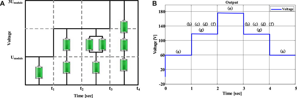
FIGURE 10. Outputs of different operational modes. (A) Different operational modes; (B) Simulation output.
In the simulation, each mode is sustained for approximately 1 s. During the interval of 2–3 s, the circuit operates in a fully series-connected mode, where the output voltage equals the sum of the voltages of the three individual battery cells. The output for the other modes is depicted in Figure 10. From the simulation output results, it becomes apparent that the current topology structure possesses the capability to output a single module. However, this might engender an imbalance among the individual battery cells. Given that the scope of this paper encompasses a DC microgrid application scenario, where it suffices to output two or three modules to maintain voltage fluctuations in proximity to the grid-side voltage, the proposed topology structure can be deemed feasible.
4.2 Controllable Charging and discharging currents
Figure 11 displays the current output waveform of the energy storage system employing this topology configuration, along with the corresponding voltage variation across the inductor terminals. During the simulation, the reference currents for optimal charging and discharging vary. The number of battery cells to be engaged and the specific battery cells to be utilized are determined based on the difference between the current circuit current and the reference current, along with the voltage disparities between individual battery cells. With changes in the reference current, the energy storage system adeptly adjusts the number of engaged battery cells, achieving the desired current value in less than 10
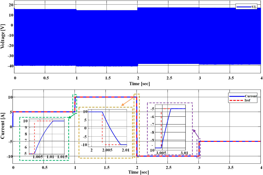
FIGURE 11. Variation of controllable charging and discharging currents and voltage across the inductor.
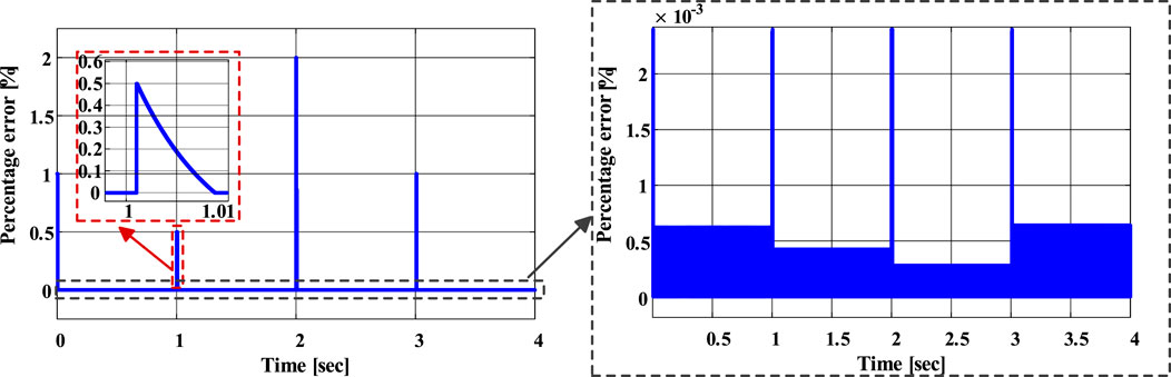
FIGURE 12. Percentage error in current.

FIGURE 13. The current and voltage variations during the first-second switching process.
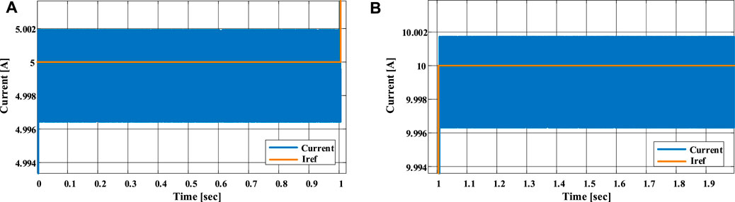
FIGURE 14. The change in current during the first switching. (A) 0–1s; (B) 1–2s.
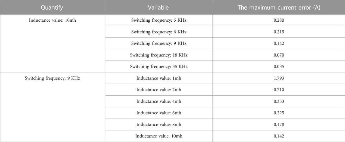
TABLE 6. The impact of different switching frequencies and inductance values on the error.
4.3 Self-balancing capability
Self-balancing capability stands as an additional advantage of this topology configuration. During the regular operation of the energy storage system, by gathering voltage data from each battery cell, the system enables higher-voltage cells to discharge first during the discharge phase, and lower-voltage cells to charge first during the charging phase, thereby achieving a balancing effect. This practice contributes to the prolongation of the energy storage system’s operational lifespan. Figure 15 validates the balancing functionality of this topology configuration. In the simulated energy storage system, individual battery cells possess varying initial SOC, with a maximum disparity of 10%. The convergence rate at the initial moment is rapid; however, as SOC converges towards the average level and voltage differences between battery cells diminish, the convergence rate gradually slows down. At the end of the simulation, the error between individual battery cells is less than 1%.
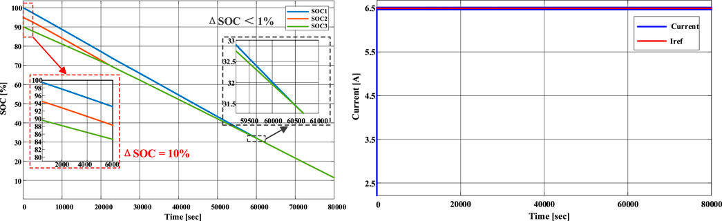
FIGURE 15. Self-balancing performance.
4.4 Comparison of losses and reliability
Taking
5 Conclusion
In the context of practical scenarios, the research domain concerning the selection and design methodology of battery topology structures for energy storage systems remains largely unexplored, and a lack of analysis regarding topology structure reliability and losses is evident in the majority of studies. This paper initiates by conducting an in-depth analysis of reconfigurable battery topology structure types. Subsequently, a quantitative assessment is performed on current MOSFET-based topologies. Following this, a dynamic reconfigurable battery topology structure suitable for DC microgrids is introduced, along with its corresponding control strategy. Finally, the feasibility of the proposed topology structure is validated through simulations in Simulink. The experimental results demonstrate that this topology structure can swiftly and stably control charge and discharge currents, reaching and maintaining the reference current value within 10
Data availability statement
The original contributions presented in the study are included in the article/Supplementary material, further inquiries can be directed to the corresponding author.
Author contributions
XY: Visualization, Writing–Original Draft. ZL: Software, Validation, Writing–Original Draft, Writing–review and editing. JZ: Conceptualization, Methodology, Supervision, Writing–review and editing. PL: Formal Analysis, Investigation, Writing–review and editing. WT: Supervision, Writing–review and editing.
Funding
The author(s) declare financial support was received for the research, authorship, and/or publication of this article. This work was supported in part by the National Natural Science Foundation of China under Grant 51607171, in part by The Institute of Electrical Engineering, CAS under Grant E155610301 and E155610201.
Acknowledgments
This is a brief acknowledgement of the contributions of individual colleagues, institutions, or agencies that assisted the writers’ efforts in the writing of this article.
Conflict of interest
The authors declare that the research was conducted in the absence of any commercial or financial relationships that could be construed as a potential conflict of interest.
Publisher’s note
All claims expressed in this article are solely those of the authors and do not necessarily represent those of their affiliated organizations, or those of the publisher, the editors and the reviewers. Any product that may be evaluated in this article, or claim that may be made by its manufacturer, is not guaranteed or endorsed by the publisher.
References
Chen, Y., Lin, E., Zhou, Y., Yu, Q., Ci, S., and Zhuang, Y. (2022). “Transient analysis in dynamic reconfigurable battery system,” in 2022 IEEE International Conference on Power Systems Technology (POWERCON), KualaLumpur, Malaysia, 12-14 September 2022, 1–6. doi:10.1109/POWERCON53406.2022.9929792
Chen, Z., Xiong, R., Lu, J., and Li, X. (2018). Temperature rise prediction of lithium-ion battery suffering external short circuit for all-climate electric vehicles application. Appl. Energy 213, 375–383. Mar. 1. doi:10.1016/j.apenergy.2018.01.068
Ci, S., Lin, N., and Wu, D. (2016). Reconfigurable battery techniques and systems: a survey. IEEE Access 4, 1175–1189. doi:10.1109/ACCESS.2016.2545338
Ci, S., Zhang, J., Sharif, H., and Alahmad, M. (2007). “A novel design of adaptive reconfigurable multicell battery for power-aware embedded networked sensing systems,” in IEEE GLOBECOM 2007 - IEEE Global Telecommunications Conference, Washington, DC, USA, 26-30 November 2007 (IEEE), 1043–1047. doi:10.1109/GLOCOM.2007.201
Ci, S., Zhang, J., Sharif, H., and Alahmad, M. (2012). “Dynamic reconfigurable multi-cell battery: a novel approach to improve battery performance,” in 2012 Twenty-Seventh Annual IEEE Applied Power Electronics Conference and Exposition (APEC), Orlando, FL, USA, 5-9 February 2012, 439–442. doi:10.1109/APEC.2012.6165857
Gan, C., Sun, Q., Wu, J., Kong, W., Shi, C., and Hu, Y. (2019). MMC-based SRM drives with decentralized battery energy storage system for hybrid electric vehicles. IEEE Trans. Power Electron. 34 (3), 2608–2621. doi:10.1109/TPEL.2018.2846622
Griffith, W. S. (2004). Optimal reliability modeling: principles and applications. Technometrics 46 (1), 112–122. doi:10.1198/tech.2004.s742
Gunlu, G. (2017). Dynamically reconfigurable independent cellular switching circuits for managing battery modules. IEEE Trans. Energy Convers. 32 (1), 194–201. doi:10.1109/TEC.2016.2616190
Han, W., Zou, C., Zhang, L., Ouyang, Q., and Wik, T. (2019). Near-fastest battery balancing by cell/module reconfiguration. IEEE Trans. Smart Grid 10 (6), 6954–6964. doi:10.1109/TSG.2019.2915013
He, L., Gu, L., Kong, L., Gu, Y., Liu, C., and He, T. (2013). “Exploring adaptive reconfiguration to optimize energy efficiency in large-scale battery systems,” in 2013 IEEE 34th Real-Time Systems Symposium, Vancouver, BC, Canada, December, 2013, 118–127. doi:10.1109/RTSS.2013.20
He, L., Kim, E., and Shin, K. G. (2017). A case study on improving capacity delivery of battery packs via reconfiguration. ACM Trans. Cyber-Physical Syst. 2, 1–23. doi:10.1145/3035539
He, L., Kong, L., Lin, S., Ying, S., Gu, Y. J., He, T., et al. (2016). RAC: reconfiguration-assisted charging in large-scale lithium-ion battery systems. IEEE Trans. Smart Grid 7 (3), 1420–1429. doi:10.1109/TSG.2015.2450727
He, L., Yang, Z., Gu, Y., Liu, C., He, T., and Shin, K. G. (2018). SoH-aware reconfiguration in battery packs. IEEE Trans. Smart Grid 9 (4), 3727–3735. doi:10.1109/TSG.2016.2639445
Kersten, A., Kuder, M., Han, W., Thiringer, T., Weyh, T., Lesnicar, A., et al. (2020). “Online and on-board battery impedance estimation of battery cells, modules or packs in a reconfigurable battery system or multilevel inverter,” in IECON 2020 The 46th Annual Conference of the IEEE Industrial Electronics Society, Singapore, 18-21 October 2020, 1884–1891. doi:10.1109/IECON43393.2020.9254515
Kim, H., and Shin, K. G. (2009). “On dynamic reconfiguration of a large-scale battery system,” in 2009 15th IEEE Real-Time and Embedded Technology and Applications Symposium, San Francisco, CA, USA, April 13 2009 to April 16 2009, 87–96. doi:10.1109/RTAS.2009.13
Kim, T., Qiao, W., and Qu, L. (2011). “Series-connected self-reconfigurable multicell battery,” in 2011 Twenty-Sixth Annual IEEE Applied Power Electronics Conference and Exposition (APEC), Fort Worth, TX, USA, 6-11 March 2011, 1382–1387. doi:10.1109/APEC.2011.5744772
Kim, T., Qiao, W., and Qu, L. (2012a). Power electronics-enabled self-X multicell batteries: a design toward smart batteries. IEEE Trans. Power Electron. 27 (11), 4723–4733. doi:10.1109/TPEL.2012.2183618
Kim, T., Qiao, W., and Qu, L. (2012b). “A series-connected self-reconfigurable multicell battery capable of safe and effective charging/discharging and balancing operations,” in 2012 Twenty-Seventh Annual IEEE Applied Power Electronics Conference and Exposition (APEC), Orlando, FL, USA, 5-9 February 2012, 2259–2264. doi:10.1109/APEC.2012.6166137
Kuder, M., Schneider, J., Kersten, A., Thiringer, T., Eckerle, R., and Weyh, T. (2020). “Battery modular multilevel management (BM3) converter applied at battery cell level for electric vehicles and energy storages,” in PCIM Europe digital days 2020; International Exhibition and Conference for Power Electronics, Intelligent Motion, Renewable Energy and Energy Management, Germany, 7 – 8 July 2020, 1–8.
Lin, N., Ci, S., Wu, D., and Guo, H. (2018). An optimization framework for dynamically reconfigurable battery systems. IEEE Trans. Energy Convers. 33 (4), 1669–1676. doi:10.1109/TEC.2018.2850853
Manenti, A., Abba, A., Merati, A., Savaresi, S. M., and Geraci, A. (2011). A new BMS architecture based on cell redundancy. IEEE Trans. Industrial Electron. 58 (9), 4314–4322. doi:10.1109/TIE.2010.2095398
Moo, C.-S., Ng, K. S., and Hsieh, Y.-C. (2008). Parallel operation of battery power modules. IEEE Trans. Energy Convers. 23 (2), 701–707. doi:10.1109/TEC.2007.914310
Quraan, M., Tricoli, P., D’Arco, S., and Piegari, L. (2017). Efficiency assessment of modular multilevel converters for battery electric vehicles. IEEE Trans. Power Electron. 32 (3), 2041–2051. doi:10.1109/TPEL.2016.2557579
Ronanki, D., and Williamson, S. S. (2019). Device loading and reliability analysis of modular multilevel converters with circulating current control and common-mode voltage injection. IEEE J. Emerg. Sel. Top. Power Electron. 7 (3), 1815–1823. doi:10.1109/JESTPE.2019.2922206
Song, Y., and Wang, B. (2013). Survey on reliability of power electronic systems. IEEE Trans. Power Electron. 28 (1), 591–604. doi:10.1109/TPEL.2012.2192503
Tashakor, N., Kacetl, J., Fang, J., Li, Z., and Goetz, S. (2023). Generic dynamically reconfigurable battery with integrated auxiliary output and balancing capability. IEEE Trans. Power Electron. 38 (7), 7933–7944. doi:10.1109/TPEL.2023.3263809
Tashakor, N., Kilictas, M., Bagheri, E., and Goetz, S. (2021). Modular multilevel converter with sensorless diode-clamped balancing through level-adjusted phase-shifted modulation. IEEE Trans. Power Electron. 36 (7), 7725–7735. doi:10.1109/TPEL.2020.3041599
Wen, J., Yu, Y., and Chen, C. (2012). A review on lithium-ion batteries safety issues: existing problems and possible solutions. Mater. Express Int. J. Multidiscip. Mater. Res. 2 (3), 197–212. doi:10.1166/mex.2012.1075
Yang, F., Gao, F., Liu, B., and Ci, S. (2022). An adaptive control framework for dynamically reconfigurable battery systems based on deep reinforcement learning. IEEE Trans. Industrial Electron. 69 (12), 12980–12987. doi:10.1109/TIE.2022.3142406
Yang, R., Xiong, R., Ma, S., and Lin, X. (2020). Characterization of external short circuit faults in electric vehicle Li-ion battery packs and prediction using artificial neural networks. Appl. Energy 260, 114253. doi:10.1016/j.apenergy.2019.114253
Zheng, T., Gao, C., Liu, X., Liao, X., Liang, J., Chen, Z., et al. (2021). A novel Z-type modular multilevel converter with capacitor voltage self-balancing for grid-tied applications. IEEE Trans. Power Electron. 36 (2), 1399–1411. doi:10.1109/TPEL.2020.2997991
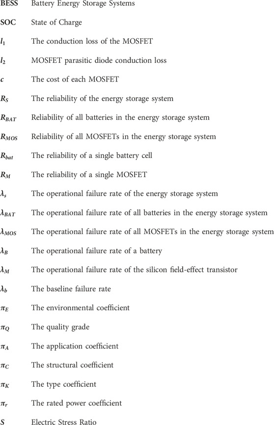
Nomenclature
Keywords: dynamic reconfigurable battery system, topology structure, switch conduction losses, reliability, battery balancing
Citation: Yang X, Liu Z, Zhu J, Liu P and Wei T (2023) Loss and reliability analysis of various solid-state battery reconfiguration topologies. Front. Energy Res. 11:1298694. doi: 10.3389/fenrg.2023.1298694
Received: 22 September 2023; Accepted: 31 October 2023;
Published: 15 November 2023.
Edited by:
Di Wu, North China Electric Power University, ChinaReviewed by:
Jingwei Liu, North China Electric Power University, ChinaYangfan Song, North China Electric Power University, China
Copyright © 2023 Yang, Liu, Zhu, Liu and Wei. This is an open-access article distributed under the terms of the Creative Commons Attribution License (CC BY). The use, distribution or reproduction in other forums is permitted, provided the original author(s) and the copyright owner(s) are credited and that the original publication in this journal is cited, in accordance with accepted academic practice. No use, distribution or reproduction is permitted which does not comply with these terms.
*Correspondence: Jin Zhu, emh1amluQG1haWwuaWVlLmFjLmNu