 Zhenggang Huo1*
 Xiaoting Zha2
- 1College of Civil Science and Engineering, Yangzhou University, Yangzhou, China
- 2Jiangsu Hydraulic Engineering Construction Co, Ltd., Yangzhou, China
In this article, a typical mixed-flow pump was adopted as the research object to investigate the influence of the inlet structure within the impeller on the performance and internal flow patterns of the mixed-flow pump. First, three different blade inlet structure cases, which are forward bending, straight, and backward bending, were proposed and modeled separately. Second, the performance of mixed-flow pumps featuring different cases was carefully compared and analyzed. The results show that the inlet structure of the blades has a small impact on the head of the mixed-flow pump. However, it has a significant impact on the efficiency and shaft power of the pump at the rated flow condition. Among them, the performance of the straight and backward bending cases is significantly better than that of the front bending case. At the same time, the accuracy of the numerical results was verified by the experimental results. Finally, the internal flow and hydraulic loss laws with different inlet structures were deeply studied. It is found that the case of forward bending will cause the media to strike the middle of the inlet edge of the blade first and then generate a secondary flow along the inlet edge. The secondary flow will induce stronger media crowding at the inlet side near the shroud and hub. Due to the large curvature of the shroud and hub at the position of intersection with the inlet side of the blade, media crowding induces flow interference of the media on each span of the impeller channel. This ultimately leads to increased flow losses within the impeller and diffuser, reducing the hydraulic performance of the mixed-flow pump. This finding clarifies the influence mechanism of the inlet side geometry of the inlet blade on the performance and internal flow of the mixed-flow pump, which can provide a theoretical basis for improving the performance of the mixed-flow pump.
1 Introduction
The specific speed of the mixed-flow pump is larger, which makes it easier to obtain higher hydraulic efficiency. This is why they are applied in many fields, such as the chemical industry, water conservancy, and agriculture (Li et al., 2020; Yang et al., 2021; Kan et al., 2022). At the same time, many use environments also put forward higher requirements for their performance and operation stability (Yang et al., 2022a; Yang et al., 2023). Therefore, researchers have carried out several studies to improve its performance and operational stability (Li et al., 2021; Yang et al., 2022b; Ji et al., 2023). A large number of studies have shown that the geometric structure of the impeller blades of a mixed-flow pump has a very significant impact on pump performance (Tan et al., 2017; Ji et al., 2021). Wu et al. (2015) made the flow structure in the impeller channel more uniform by geometrically correcting the outlet side of the impeller blades of the mixed-flow pump, which significantly widened the flow range of the mixed-flow pump and improved its hydraulic efficiency under high-flow conditions. Based on numerical simulation and experiments, Bing and Cao (2014) explored in detail the influence of position parameters at the inlet and outlet of the blade on the hydraulic loss and performance of the mixed-flow pump. It is found that reducing the blade angle on the blade trailing edge is conducive to reducing the absolute velocity in the outlet area, which, in turn, reduces the hydraulic loss in the region and improves the hydraulic efficiency of the mixed-flow pump. Bing and Cao (2013) also took multiple geometric parameters of the impeller blade as independent variables at the same time, carried out a large number of numerical simulations, and conducted performance tests on the case with better performance. It is found that the hydraulic performance of the mixed-flow pump can be effectively improved by combining different geometric parameters of the blades to carry out a large number of numerical simulations, but this work requires a lot of computational resources and time. Tan et al. (2018) investigated the influence of tip position and shape of mixed-flow pump blades on tip leakage and performance of the mixed-flow pump, and proposed the structure of a T-shaped tip. This structure can not only improve the hydraulic efficiency of the pump but also significantly reduce the pressure fluctuation intensity at the blade tip clearance.
Among the parameters of the mixed-flow pump blade, the parameters of the leading edge were found to have a significant impact on the pump performance and operation stability. Zhu et al. (2019) optimized the symmetric leading-edge shape of the mixed-flow pump based on a genetic algorithm and numerical simulation. The results show that the fine-tuning of the blade inlet side section can significantly improve the cavitation performance without affecting the efficiency and head of the pump. Kim et al. (2022) investigated the effect of the transition surface shape from the working surface to the back surface at the inlet side of the blade on the flow structure within the impeller of a mixed-flow pump in the non-cavitation state versus the cavitation state. It was shown that the transition surface shape of the square shape induces significant flow separation and vortex generation in the non-cavitation state. In the cavitation state, the greater the ellipticity of the transition connection between the working surface and the back surface, the stronger its anti-cavitation performance. Brennen (2011) studied the influence of the sharp degree of the blade inlet edge shape on the performance of the mixed-flow pump under non-cavitation and cavitation conditions. It is found that the sharper the shape of the blade inlet edge, the better the performance of the mixed-flow pump. However, when the inlet edge is too sharp, there is a risk of being left out of focus because of the shutter. Tao et al. (2018) similarly carried out research on the influence of inlet side structures with different shapes on the cavitation performance of the pump at rated flow. It is found that the shape of the leading edge of the blade will strongly affect the flow separation, pressure drop, and cavitation of the medium, and the prediction of the low-pressure region at the position of the leading edge can be used as a critical assessment index for the pump cavitation performance. Ardizzon et al. (1995) studied the influence of the blade leading-edge attack angle on medium flow. The influence of the incident angle of the medium on the cavitation performance of the pump was discussed. It was found that the flow mode and local pressure peak of the medium were the most closely related parameters to the cavitation performance.
Scholars have already recognized that the geometric structure of the blade inlet edge has a significant impact on the pump performance and operation stability. However, the existing research mainly focuses on the influence of the blade leading-edge shape on pump cavitation performance, while the influence of the inlet edge shape on pump performance has not been found. Based on the research method of combining numerical calculations and experimental verification, this paper studies the influence of the inlet edge shape on the performance and internal flow structure of the mixed-flow pump in order to provide some help for improving the performance and operation stability of mixed-flow pumps.
2 Geometry and parameters
The research object of this paper is a small mixed-flow pump used for water cooling of a large mechanical system. The structure of the mechanical system limits the outer diameter of the pump body to no more than 100 mm. So, the maximum radial size of the model meridian is limited to 90 mm. The design flow of the mixed-flow pump model is Qr = 30 m3/h. In order to meet the requirements of the piping arrangement of the mechanical system, the head of pump Hr under the design flow shall not be less than 10 m. The rated operating speed of the water pump is nr = 6000 r/min. On this basis, we can determine the specific speed of the hydraulic model under the rated flow as follows:
Due to the high head and efficiency requirements of this hydraulic model under the rated flow condition, the impeller is of the meridian closed type, and the pressure chamber adopts the space diffuser to meet the design requirements. Figure 1 shows the meridian of the main overflow components of the mixed-flow pump. Figure 2 shows the hydraulic model of the impeller blade inlet side of the three geometric structures of the program. The main dimensions marked in the figure have been listed in Table 1.
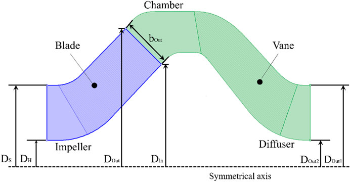
FIGURE 1. Meridian of the main overflow components of mixed-flow pumps.
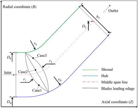
FIGURE 2. Three geometric structure cases for the inlet side of impeller blades.
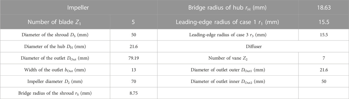
TABLE 1. Geometric specifications of the impeller and the diffuser.
3 Numerical modeling
3.1 Mathematical model
NX software is adopted for three-dimensional modeling of the mixed-flow pump hydraulic system in this paper. As the most central hydrodynamic components, the blade modeling accuracy of the impeller and diffuser has a great impact on the accuracy of the numerical results. Therefore, the method of determining surfaces from point sets is used for blade modeling of impellers and diffusers. The large amount of point data in the point set not only ensures the accuracy of blade modeling but also ensures that the shape of the blade in the numerical simulation model has a high degree of consistency with that of the rapid prototyping blade used for testing. For this mixed-flow pump, its inlet and outlet pipelines in the cooling system are straight pipes, and the inlet and outlet pipe lengths are long. Therefore, the inlet and outlet pipes in the three-dimensional modeling process are also in the form of straight pipes, and the length is 10 times the impeller inlet diameter to ensure the accuracy of the numerical simulation.
3.2 Grids
The use of a structured hexahedron grid in numerical calculation not only improves the speed of data transmission and thus reduces the time of numerical simulation but also improves the quality of data transmission and the convergence of numerical calculation. The grids used in different numerical calculation cases in this paper are all hexahedral structured grids which are generated in Ansys TurboGrid software. At the same time, 15 layers of the boundary layer are arranged near the solid wall within the calculation domain, and the growth rate of the boundary layer is set as 1.05. However, at the inlet side of the impeller blade, the number of layers of the boundary layer is set to 20 in order to capture the fine flow structure of the medium. The grid assembly of the main computational domain and the details of each case are shown in Figure 3.

FIGURE 3. Grid details of main hydraulic components.
In order to further reduce the influence of the grid on the numerical results, the grid independence analysis was also carried out in this paper. On the basis of ensuring that the included angles of the edges are greater than 18°, the performance analysis of the mixed-flow pump in case 2 was carried out for the change of the single side length of the hexahedral grid (the maximum control size of the grid). It can be seen from Table 2 that when the control size of the grid does not exceed 1.8, the fluctuation of the numerical prediction results of the head and efficiency of the mixed-flow pump does not exceed 1%. At this time, the influence of the grid on the results of numerical calculations is small, so 1.8 is chosen as the control size of the subsequent grid used for numerical calculations.

TABLE 2. Grid independence analysis.
3.3 Boundary conditions
In order to further improve the accuracy of numerical calculations, the pre-settings of the numerical cases should take into account the convergence of the case and the real situation of the mixed-flow pump. As shown in Figure 4, in order to enhance the convergence of the numerical case, the boundary conditions in this paper adopt the inlet total pressure and the outlet mass flow rate. Because the impeller of the mixed-flow pump is made of precision-cast stainless steel, its roughness is low, so the solid wall in the calculation domain is set to no-slip wall, and the roughness is set to 10 um. In addition to the impeller calculation domain being set to rotate, the other calculation domains are set to stationary. The impeller and the front and back calculation domains are connected by the frozen rotor to ensure the accuracy of data transfer. The convergence accuracy of the numerical calculation is set to 10−4 to ensure the accuracy of the calculation results.
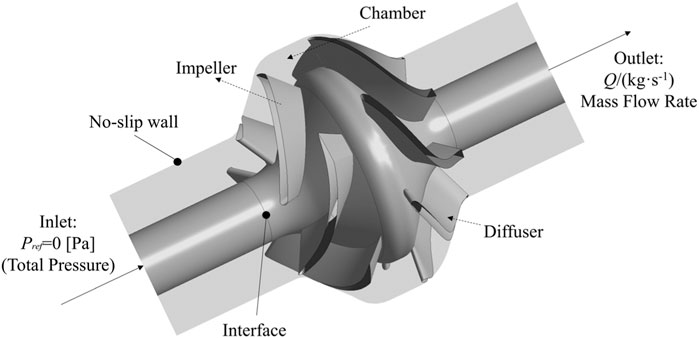
FIGURE 4. Computational domain model and boundary conditions.
The k-ω SST turbulence model has obvious advantages in high-precision boundary layer simulation, and it has high accuracy in predicting the flow structure near the wall of the impeller blade. The resolution of the boundary layer needs to be more than 10 points to ensure the conditions for the use of the model (Menter, 1994). The grid used in this paper fully meets the requirements, so the numerical calculation model used in this paper is the k-ω SST turbulence model. The following two equations are the transport equations for the turbulent kinetic energy, k, and the turbulence frequency, ω.
The
Here, μt is the turbulence viscosity. Pkb and Pωb represent the influence of the buoyancy forces. Pk is the production rate of turbulence.
4 Results and discussion
4.1 Pump performance validation
In order to further ensure the accuracy of numerical calculation results, performance test verification was carried out in this paper. In the three cases, the impeller blade inlet side structure in case 2 is a straight line from the shroud to the hub, which is the most convenient for the machining accuracy verification of the test model. Therefore, case 2 is selected to carry out the verification performance test. The test was carried out on a closed test bench. The pressure at the inlet and outlet of the mixed-flow pump was collected using the pressure sensor at the inlet and outlet, and transmitted to the computer in real time to calculate the pump head. The real-time flow of the pump is obtained using the electromagnetic flowmeter, and the shaft power and pump speed are obtained using the torque meter. Figure 5 shows a sketch of the experimental system and for the case 2 impeller and diffuser in kind. The impeller is made of stainless steel by precision casting, and the diffuser is made of the original physical model of the pump manufacturer. The production process is the disappearing mold casting.
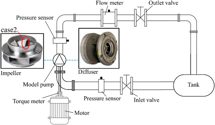
FIGURE 5. Test bench system.
Figure 6 shows the comparison between the numerical prediction results of the model of case 2 and the experimental results. Under the rated flow condition, the numerically predicted head is 1.08% higher than the experimental head, and the numerically predicted efficiency is 1.15% higher than the experimental efficiency, so the numerically predicted results have high accuracy. The reason that the numerical prediction results are slightly higher than the experimental results under the rated flow condition is that there is a small amount of volumetric and mechanical losses during the experimental process. Under the small flow condition, the error between the numerically predicted head and the experimental head remains small. However, the error between the numerically predicted and experimental efficiencies increases slightly and reaches a maximum value of 4.24% at 0.6 times the rated flow condition. At high flow conditions, the predictions of head and efficiency increase with the increase in the flow rate. At 1.4 times the rated flow condition, the numerical prediction error of the head reaches a maximum of 1.61 m, and the numerical prediction error of efficiency reaches a maximum of 3.99%. The main reason for the increased deviation of the numerical prediction results for the non-rated flow condition compared to the rated flow condition is the elevated intensity of the unsteady flow in the flow field. The true head and efficiency of the pump show periodic fluctuations, which cannot be reproduced by steady-state numerical simulation. In conclusion, the numerical method in this paper has a small error in predicting the pump performance near the rated flow condition, and the error in predicting the performance under the deviation from the rated flow condition is slightly improved, but the prediction error in the full flow range does not exceed 4.5%. Moreover, the numerical prediction of head and efficiency in the trend of change with the test results also maintains a high degree of consistency, and the prediction of the pump’s highest efficiency point is very accurate. In summary, the numerical method used in this paper has high accuracy.
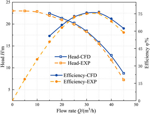
FIGURE 6. Comparison of numerical predictions of pump performance with test results.
4.2 Comparison of performance under different inlet side cases
Figure 7 shows the performance comparison of the mixed-flow pump under three different impeller blade inlet side cases. It can be seen from Figure 7A that the pump head of case 1 is higher than that of the other two cases under small flow and large flow conditions. However, within the range of 0.8 Qr∼1.0 Qr, the difference between the pump heads of case 1 and case 2 is small. The head of case 3 is smaller than that of the other two cases under full flow conditions. Combined with the axial projection of each case in Figure 1, it can be seen that the axial projection area of case 3 is the smallest, so the contact area between the impeller blade and the medium is the smallest, which is the reason for its low head. For case 3, the minimum projected area of its axial plane causes its head to be low, but Figure 7C shows that its axial power is significantly lower than that of the other two cases under full flow conditions. Moreover, compared with the other two cases, the maximum shaft power point shifts to the rated flow point, so it has better non-overload performance. Comparing the efficiency of the three cases, it can be seen that the efficiency performance of case 1 is the worst in the range of 0.6 Qr∼1.0 Qr, the efficiency performance of case 3 is the worst under the condition of large flow (1.4 Qr), and the efficiency range of case 2 is the largest. Since this mixed-flow pump often operates in the range of 0.75 Qr ∼1.08 Qr, the energy-saving effect of case 2 and case 3 is significantly better than that of case 1.
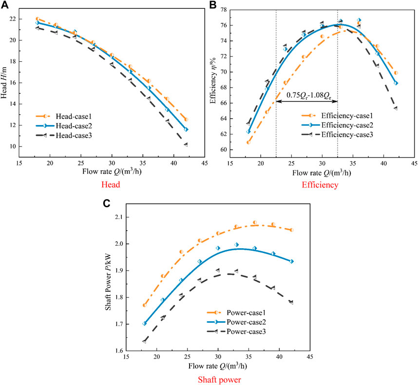
FIGURE 7. Performance under different inlet side cases.
4.3 Flow field pattern with a mixed-flow pump
Figure 8 shows the circumferential flow angle of the medium on the mid-span of the impeller channel of different cases. Under the condition of a small flow rate, the media flow angle of each case has an obvious uneven distribution in the circumferential direction, and the difference between each case is small. The specific performance is that the media flow angle of the medium near the back of the blade is significantly smaller than that near the working surface of the blade. Meanwhile, the uniformity of the medium flow angle in the circumferential direction of each scheme is significantly improved at rated flow conditions. However, the distribution difference among the cases is significantly elevated. Near the back of the impeller blade, the high media flow angle area of case 1 extends to the impeller outlet. This indicates that the media at this position has a secondary flow perpendicular to the mainstream direction. However, near the working surface of the blade, the media flow angle distribution of the media and other areas of the channel have obvious stratification. This may be caused by the impact of the media at the blade inlet on the blade inlet edge. At the same time, the secondary flow in the channel caused by the uneven distribution of the media flow angle in the channel will also induce the uneven distribution of the impeller outlet flow in the circumferential direction. It can be seen that the media flow angle in region 2 is significantly smaller than that in the regions on both sides, which will lead to stronger “wake-jets” in the medium at the impeller outlet and, thus, induce a stronger rotor–stator interaction. Compared with case 1, case 2 and case 3 have a significantly more uniform circumferential distribution of the media flow angle under rated flow conditions, which is more conducive to reducing its hydraulic loss and improving its operation stability.
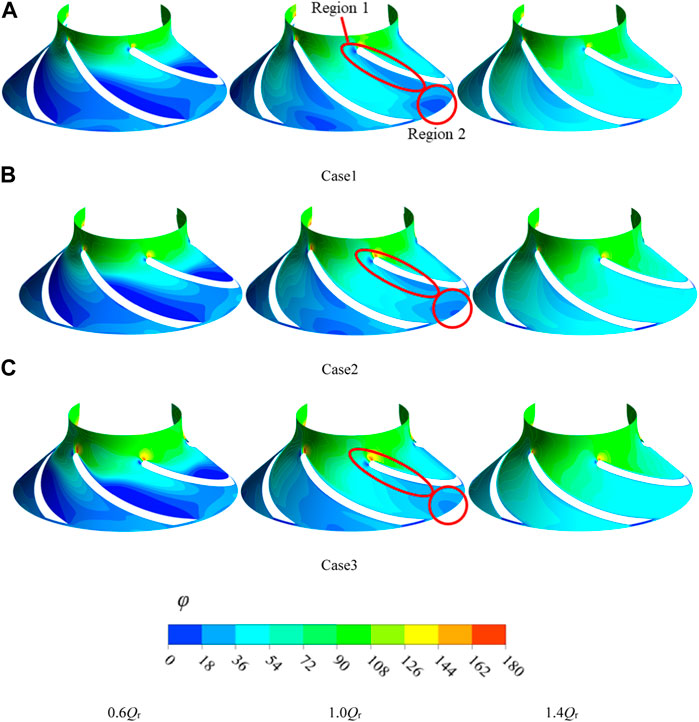
FIGURE 8. Circumferential media flow angle on the mid-span of the impeller channel for different cases.
The velocity gradient distribution in the span direction at the mid-span position of the impeller channel for different cases is shown in Figure 9. Under small flow conditions, the overflow area of the impeller channel is larger than the area required for uniform media overflow. As a result, there is an obvious interference of the medium on each span, which is manifested in the presence of a clear region of high values of the velocity gradient in the first half of the impeller channel. Among them, the region of high values of the velocity gradient in case 1 is from the position of the blade inlet and occupies the entire flow path from the back of the blade to the working surface. It indicates that in these regions, there is flow interference of the medium in the span direction. Compared to case 1, the influence range of this high-velocity gradient region in case 2 is slightly reduced, but the flow interference of the medium on each span is still more obvious. Case 3 is in the region of the smallest range of influence, and its location is not near the impeller blade inlet edge but in the middle of the impeller channel near the back of the blade. This suggests that the shape of the blade inlet edge of case 3 is effective in reducing the media flow interference on each span. It also indicates that the high-velocity gradient region in cases 1 and 2 may be caused by the flow separation between the inlet edge and the middle position of the flow path. Under the rated flow condition, the effect of the blade inlet edge structure on the media flow interference on each span still exists. First, the overall velocity gradient in the flow channel of case 1 is significantly higher than that of the other two cases, and case 3 has the smallest overall velocity gradient. At the same time, there is an obvious flow interference in region 3 between the spans at the impeller outlet position in case 1. This also shows that the change in the geometric structure of the inlet side of the blade not only affects the flow in the impeller channel but also directly changes the flow pattern of the medium at the outlet of the impeller, which, in turn, affects the flow structure of the medium in the diffuser.

FIGURE 9. Flowfield pattern at the mid-span surface of cavities under different flow conditions.
In order to further analyze the flow difference of the medium in the direction from the shroud to the hub, Figure 10 shows the medium flow rate on the 0.8-span cross section near the shroud and the 0.2-span cross section near the hub under the rated flow condition. Combined with the flow interference analysis of each span in Figure 10, the axial projection diagram of the influence of the impeller blade inlet structure on the medium flow is drawn. At the position of the 0.2-span cross section, the influence of the blade inlet structure on the distribution of medium velocity is very obvious. The forward curved inlet edge structure in case 1 will cause the medium to hit the middle of the inlet edge the first time. Because the inlet edge has a certain thickness, its crowding out of the medium will cause the medium to generate a secondary flow along the path of the dotted line in the schematic diagram. This will inevitably lead to an increase in the flow on the 0.2 span and 0.8 span cross sections near the shroud and hub and, thus, strengthen the medium crowding at the blade inlet near the cover plate. From the velocity distribution diagram, it can be seen that the 0.8-span cross section of case 1 has an obvious low-velocity region near the inlet side of the blade, which is caused by the medium hitting the inlet of the blade. The low-velocity region is bound to cause more hydraulic losses. In addition, in case 2, the low-speed area of the scope of the obvious reduction, this is because the program does not have the above secondary flow. However, comparing the velocity distributions at the 0.2 span and 0.8 span inlet locations in cases 1 and 2, it can be found that the inlet crowding phenomenon on the 0.8-span cross section is significantly stronger than that on the 0.2-span cross section. This is because the excessive arc curvature of the shroud is smaller, and the change of the flow direction of the medium is more obvious when it passes near this position, and flow interference between the spans is more likely to occur, which leads to hydraulic loss. On the other hand, on 0.2 span, the large curvature transition section of the rear cover plate is helpful in preventing inter-span flow interference. In case 3, the medium first hits the inlet side of the blade near the shroud and hub, which causes the secondary flow in the opposite direction of case 1. This avoids the superposition of the high-intensity region of the flow interference between the spans and the region near the shroud with a smaller curvature. The media crowding at the inlet side of the blade near shroud is significantly reduced. At the same time, the case 2 and case 3 impeller outlet position of the media flow distribution is also significantly more uniform, which is conducive to reducing the rotor–stator interaction of the hydraulic system.
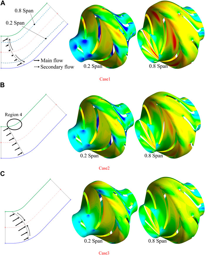
FIGURE 10. Media flow rate in the 0.8-span cross section and 0.2-span cross section at the rated flow condition and media flow near the inlet.
The entropy production statistics in the impeller, diffuser, and overall calculation domains of different cases are shown in Figure 11. For the impeller calculation domain, the entropy production of case 1 under 0.8 Qr and 1.0 Qr flow conditions is significantly larger than that of the other two cases, which is in good agreement with the previous analysis. In addition, from Figure 10B, it can be seen that there is also a significant difference in the hydraulic losses within the diffuser under different inlet side structures. The previous analysis found that the uneven flow phenomenon of the medium near the impeller outlet in case 1 is more obvious, which directly leads to the entropy production within the diffuser in the working condition range of 0.6 Qr∼1.2 Qr that is significantly higher than in the other two cases. The entropy production statistics of the overall calculation are shown in Figure 10C, and the difference in entropy production under the 0.8 Qr working condition of each case is the largest, which coincides with the results of the efficiency analysis in Figure 8.
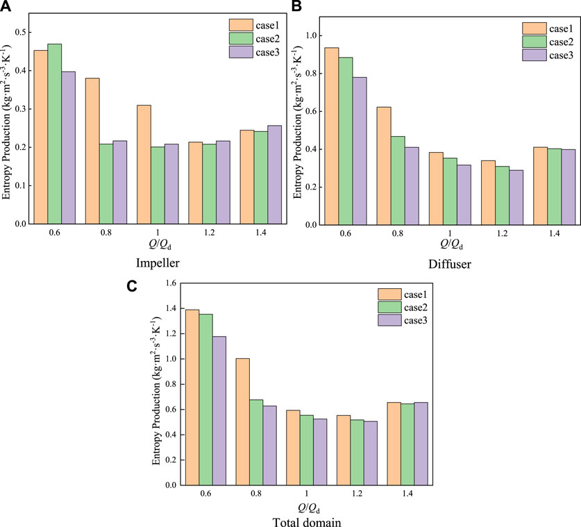
FIGURE 11. Pressure distribution on the mis-span midline within the chamber.
5 Conclusion
The influence of the blade leading-edge structure on the performance and internal flow pattern of a mixed-flow pump is studied in this work. Different impeller blade leading-edge cases which are forward curved, straight, and backward curved are designed. Numerical calculations are carried out for different cases. The performance difference of each case is carefully compared and analyzed with respect to the internal flow characteristics. As it is shown, the main conclusions can be extracted as follows:
1) Based on the performance test, the numerical prediction error at the rated flow condition is less than 1.2%. Meanwhile, the numerical prediction error is less than 4.5% under off-rated flow rates. More importantly, the prediction of the performance change law is quite accurate. Therefore, the numerical method adopted in this paper ensures a high degree of accuracy.
2) The forward curvature of the inlet side of the blade induces a secondary flow of the medium across the span near this location, which, in turn, leads to a stronger medium crowding that occurs close to the location of the shroud. This region will overlap with the region of a greater curvature of the shroud, resulting in greater hydraulic losses.
3) The unsteady flow described in the second conclusion will also result in the presence of a significantly uneven flow in the impeller outlet medium. This will not only increase the flow losses within the diffusers but will also increase the intensity of the rotor–stator interaction in the hydraulic system.
Data availability statement
The original contributions presented in the study are included in the article/Supplementary material; further inquiries can be directed to the corresponding author.
Author contributions
ZH: writing–original draft. XZ: writing–review and editing.
Funding
The author(s) declare financial support was received for the research, authorship, and/or publication of this article. The authors thank Scientific Research and Innovation Plans for Postgraduate of Jiangsu Province (No. KYCX22_3437).
Conflict of interest
Author XZ was employed by Jiangsu Hydraulic Engineering Construction Co, Ltd.
The remaining author declares that the research was conducted in the absence of any commercial or financial relationships that could be construed as a potential conflict of interest.
Publisher’s note
All claims expressed in this article are solely those of the authors and do not necessarily represent those of their affiliated organizations, or those of the publisher, the editors, and the reviewers. Any product that may be evaluated in this article, or claim that may be made by its manufacturer, is not guaranteed or endorsed by the publisher.
References
Ardizzon, G., and Pavesi, G. (1995). Theoretical evaluation of the effects of the impeller entrance geometry and of the incident angle on cavitation inception in centrifugal pumps. Proc. Institution Mech. Eng. Part C J. Mech. Eng. Sci. 209 (1), 29–38. doi:10.1243/PIME_PROC_1995_209_119_02
Bing, H., and Cao, S. (2013). Multi-parameter optimization design, numerical simulation and performance test of mixed-flow pump impeller. Sci. China Technol. Sci. 56, 2194–2206. doi:10.1007/s11431-013-5308-0
Bing, H., and Cao, S. (2014). Parametrization of blade leading and trailing edge positions and its influence on mixed-flow pump performance. Proc. Institution Mech. Eng. Part C J. Mech. Eng. Sci. 228 (4), 703–714. doi:10.1177/0954406213490104
Ji, L., Li, S., Li, W., Huang, Y., Shi, W., Yang, Y., et al. (2023). Study on passive suppression method of rotating stall in mixed-flow pump: using different impeller rim structures. Proc. Institution Mech. Eng. Part A J. Power Energy 237, 965–984. doi:10.1177/09576509231153304
Ji, L., Li, W., Shi, W., Tian, F., and Agarwal, R. (2021). Effect of blade thickness on rotating stall of mixed-flow pump using entropy generation analysis. Energy 236, 121381. doi:10.1016/j.energy.2021.121381
Kan, K., Binama, M., Chen, H., Zheng, Y., Zhou, D., Su, W., et al. (2022). Pump as turbine cavitation performance for both conventional and reverse operating modes: a review. Renew. Sustain. Energy Rev. 168, 112786. doi:10.1016/j.rser.2022.112786
Kim, Y. I., Yang, H. M., Lee, K. Y., and Choi, Y. S. (2022). Numerical investigation on blockage-related cavitation surge and pressure gain of a mixed-flow pump with influence of blade leading edge shape on suction performance. J. Fluids Eng. 144 (9), 091205. doi:10.1115/1.4053956
Li, W., Ji, L., Li, E., Shi, W., Agarwal, R., and Zhou, L. (2021). Numerical investigation of energy loss mechanism of mixed-flow pump under stall condition. Renew. Energy 167, 740–760. doi:10.1016/j.renene.2020.11.146
Li, W., Li, E., Ji, L., Zhou, L., Shi, W., and Zhu, Y. (2020). Mechanism and propagation characteristics of rotating stall in a mixed-flow pump. Renew. Energy 153, 74–92. doi:10.1016/j.renene.2020.02.003
Menter, F. R. (1994). Two-equation eddy-viscosity turbulence models for engineering applications. AIAA J. 32 (8), 1598–1605. doi:10.2514/3.12149
Tan, L., Xie, Z., Liu, Y., Hao, Y., and Xu, Y. (2018). Influence of T-shape tip clearance on performance of a mixed-flow pump. Proc. Institution Mech. Eng. Part A J. power energy 232 (4), 386–396. doi:10.1177/0957650917733129
Tan, L., Yu, Z., Xun, Y., Liu, Y., and Cao, S. (2017). Role of blade rotational angle on energy performance and pressure fluctuation of a mixed-flow pump. Proc. Institution Mech. Eng. Part A J. power energy 231 (3), 227–238. doi:10.1177/0957650917689948
Tao, R., Xiao, R., and Wang, Z. (2018). Influence of blade leading-edge shape on cavitation in a centrifugal pump impeller. Energies 11 (10), 2588. doi:10.3390/en11102588
Wu, D., Yan, P., Chen, X., Wu, P., and Yang, S. (2015). Effect of trailing-edge modification of a mixed-flow pump. J. Fluids Eng. 137 (10), 101205. doi:10.1115/1.4030488
Yang, F., Li, Z., Hu, W., Liu, C., Jiang, D., Liu, D., et al. (2022b). Analysis of flow loss characteristics of slanted axial-flow pump device based on entropy production theory. R. Soc. Open Sci. 9 (1), 211208. doi:10.1098/rsos.211208
Yang, F., Li, Z., Yuan, Y., Lin, Z., Zhou, G., and Ji, Q. (2022a). Study on vortex flow and pressure fluctuation in dustpan-shaped conduit of a low head axial-flow pump as turbine. Renew. Energy 196, 856–869. doi:10.1016/j.renene.2022.07.024
Yang, Y., Zhou, L., Shi, W., He, Z., Han, Y., and Xiao, Y. (2021). Interstage difference of pressure pulsation in a three-stage electrical submersible pump. J. Petroleum Sci. Eng. 196, 107653. doi:10.1016/j.petrol.2020.107653
Yang, Y., Chen, X., Bai, L., Yao, Y., Wang, H., Ji, L., et al. (2023). Quantification and investigation of pressure fluctuation intensity in a multistage electric submersible pump. Phys. Fluids 35 (3). doi:10.1063/5.0136664
Keywords: mixed-flow pump, unsteady flow, leading edge, secondary flow, turbulence
Citation: Huo Z and Zha X (2023) Influence of blade leading-edge form on the performance and internal flow pattern of a mixed-flow pump. Front. Energy Res. 11:1292387. doi: 10.3389/fenrg.2023.1292387
Received: 11 September 2023; Accepted: 11 October 2023;
Published: 26 October 2023.
Edited by:
Leilei Ji, Jiangsu University, ChinaReviewed by:
Qixiang Hu, Changzhou Institute of Technology, ChinaHao Chang, Jiangsu University, China
Copyright © 2023 Huo and Zha. This is an open-access article distributed under the terms of the Creative Commons Attribution License (CC BY). The use, distribution or reproduction in other forums is permitted, provided the original author(s) and the copyright owner(s) are credited and that the original publication in this journal is cited, in accordance with accepted academic practice. No use, distribution or reproduction is permitted which does not comply with these terms.
*Correspondence: Zhenggang Huo, emdhbmdodW9AMTI2LmNvbQ==