 Chen Feng
 Pingfeng Ye
 Zhengzhong Gao
 Haiyang Jiang
 Xiangyu Zang
 Xiangxing Zhang
- College of Electrical Engineering and Automation, Shandong University of Science and Technology, Qingdao, China
At present, the power supply system of 5G base stations is a micro smart grid, it generally uses 240 V DC power supply with multiple branches, and leakage accidents will threaten personal and property safety, so it is vital to identify the fault line accurately and remove the faults rapidly. In this paper, the leakage phenomenon of transmission lines in the HVDC power supply system of a 5G communication base station is studied. To address the issue of multi-branch line leakage diagnosis and line selection in the 240 V DC system, a new distributed DC insulation monitoring and fault line selection technology and system are proposed. The distributed DC insulation monitoring line selection technology is used to collect the leakage current of each branch by setting a unique single-core DC leakage transformer and process the signal primarily. In addition, a high-resistance bridge switchgear is added to the bus bar. According to different leakage currents caused by the imbalance of the bridge before and after the switch, the insulation resistance of electrodes to the ground is calculated accurately, which solves the problem that the current technology cannot judge the fault of the positive and negative electrodes to the ground at the same time. Through both simulation and prototype experiments, the feasibility of this technology and system device in line insulation monitoring and line selection of the HVDC communication base station power supply system is verified.
1 Introduction
Currently, a high-voltage DC power supply system with a voltage level of 240 V is widely used as equipment in a signal system, transformer substation, and communication station because of the complicated environment (Hellgren, 2004; Li, 2012; Chen, 2018a). As these DC power supply systems include many branches and loads, when the line insulation drops, it is easy to cause grounding, short circuit, and other faults, endangering personal safety or equipment safety. Therefore, it is necessary to have a corresponding insulation monitoring device, which can give early warning and lock the fault location quickly.
At present, the integral insulation monitoring and protection technology is adopted in the power supply of communication station usually. However, it is impossible to select and locate the faulty branch accurately. The existing insulation monitoring methods with the function of fault branch selection include the balance-bridge method and signal injection method. However, there are also many problems in these methods. For the balance-bridge method of fault line selection, it is necessary to set the bridge’s parameters accurately, according to the system type (Huang et al., 2019). If the value of the bridge parameter is low, the insensitivity of the insulation monitoring system will cause an inaccuracy of the fault judgment. On the contrary, if the value of the bridge parameter is high, the test data will have large deviation and the equipment maintenance cost will increase. Furthermore, it is difficult to detect the simultaneous decline of positive and negative insulation resistances to the ground with current technology (Luo et al., 2016). In order to detect the insulation state of each electrode, switchable bridges need to be installed in each branch. This bridge has caused the line-to-ground insulation resistance to drop actually. For each additional bridge, the equivalent value of the ground resistance will be doubled, and the risk of personal electric shock will increase accordingly (Jiang and Ji, 2009; Yin et al., 2012; Rybski et al., 2015). At the same time, on one hand, the active power leakage current sensor installed in the branch is costly; on the other hand, it is ineffective to detect all kinds of insulation faults. The signal injection method is greatly affected by the electrical distribution parameters, and it is impossible to judge the insulation drop in the complicated environment (Yow-Chyi and Chen-You, 2012; Olszowiec, 2017).
To solve these issues, a distributing–collecting online insulation monitoring system is proposed. It adopts the single-core DC-type current transformers settled in each branch to collect the micro-current after the insulation fault. Ground insulation monitoring and line selection can also be realized under various insulation faults. This paper mainly includes the following aspects: the principle and technology of leakage protection are analyzed, and the sensor suitable for the distributed acquisition system is studied. The advantages and disadvantages of current leakage protection technology are compared and analyzed. A novel distributing–collecting on-line insulation monitoring system is proposed, which is more suitable for the DC transmission system of communication base stations and the use of remote electrical equipment. The hardware structure and algorithm principle of the proposed system are developed and designed. It is best to build the analog communication base station of the DC transmission system using MATLAB software verification and prototype verification, carry out experimental verification, and analyze the results to verify the effectiveness of the system device.
2 Method
2.1 Personal electrical safety issues and insulation monitoring settings
With reference to the provisions of China’s electrical safety regulations (GB/T 13870.2-2016), the human body safety current in the DC system is no more than 50 mA, i.e., when the current flowing through the human body is below 50 mA, it is not life-threatening, and people who are subjected to an electric shock can react in time and avoid continuous injury (Dawalibi et al., 1990). For the DC power supply system, it is stipulated that the product of the human electric shock current and the action time is not more than 30 mA s. By imitating the safety parameters of the AC system, the safety parameter for the DC system can be stipulated as 50 mA s. According to China’s human body safety current standard, adult men’s threshold to get rid of the electric shock should be no more than 10 mA (Roberts, 2009; Zhao et al., 2017; Zhenbin et al., 2021).
As shown in Figure 1, the line in the figure represents the line of the general DC power supply system. When a person touches the positive pole or negative pole of the line and the insulation of the other pole drops, an electric shock accident will occur.
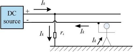
FIGURE 1. DC personal electric shock safety diagram.
Generally, the resistance of the human body rbady is regarded as 1 kΩ, and the voltage level of the DC power supply system for the communication system is 240 V.
Calculated by Eq. 1, when the insulation resistance rk of the line (positive or negative pole) drops to 3.8 kΩ, if the person happens to touch the other pole (negative or positive pole) of the line, the current flowing through the person is 50 mA (human body safety current for the DC system). When the insulation resistance of the line drops to 24 kΩ, the current flowing through the body is 9.6 mA (the threshold current to get rid of the electric shock).
In order to guarantee the human safety and ensure certain reliability, the current flowing through a person must be controlled under 50 mA. Since the communication system powered by the DC power supply system is generally installed in a high tower, there is a great danger of muscle suppression caused by an electric shock. Therefore, for avoiding an electric shock and enabling people to get rid of the electric shock in time, it is recommended to set the tripping operation setting as 28 kΩ (1.2 times of 24 kΩ).
2.2 Distributed online insulation monitoring system
2.2.1 The structure of a distributed online insulation monitoring system
Aiming at the deficiency of the existing insulation monitoring system, this paper proposes a distributed online insulation monitoring system. Figure 2 displays the distributed insulation monitoring system. The whole system consists of a centralized central processing unit and a dedicated DC residual current transformer distributed in each branch. Positive and negative cable currents in each branch pass through the special DC residual current transformer proposed in this paper at the same time, and the residual current of each branch is extracted using the principle of the current magnetic field effect canceling each other in the positive and negative cables for insulation monitoring. All control signal transmission, signal collection, and processing are integrated in the central processing unit of the distributed insulation monitoring device. The central processing unit uniformly sends out the control signal, controls, and modulates the special DC transformer to collect the signal, and the collected signal is uniformly processed by the central processing unit. CT1, CT2, … CTn are DC insulation monitoring transformers installed in each branch, and CTall is the DC insulation monitoring transformer, which is installed at the bus with a high resistance to ground. R1+, R1-, R2+, R2- … Rn+, and Rn- are the insulation resistances of each branch. Ra and Rb are the balanced high resistance to the ground of the bus.
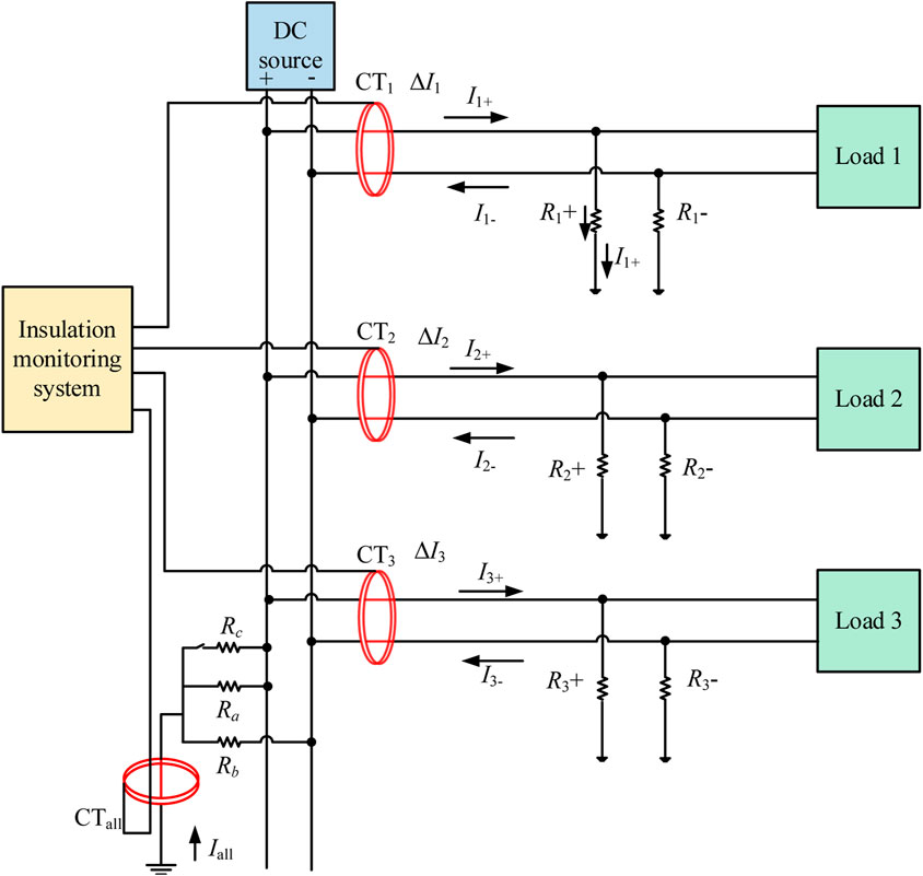
FIGURE 2. Distributed online insulation monitoring system.
The entire system consists of a central processing unit and DC residual current transformers distributed over the branches. The transformer collects residual current of each branch for insulation monitoring by the principle that the magnetic field created by current in different directions cancels each other out.
2.2.2 Distributed online insulation monitoring transformer
By studying the existing magnetic modulation current transformers, a new insulation monitoring transformer is presented, which is more durable, precise, economical, and practical. The existing magnetic modulation current transformers are all active transformers; they usually require a control circuit, and a signal processing and amplifying circuit in them. An alternating current signal is added to the magnetic core, so the direct current of the DC power system can be extracted on the secondary side of the transformer. The current transformer is shown in Figure 3 (Chen and Sun, 2018; Xie et al., 2016; M; Shi et al., 2022).
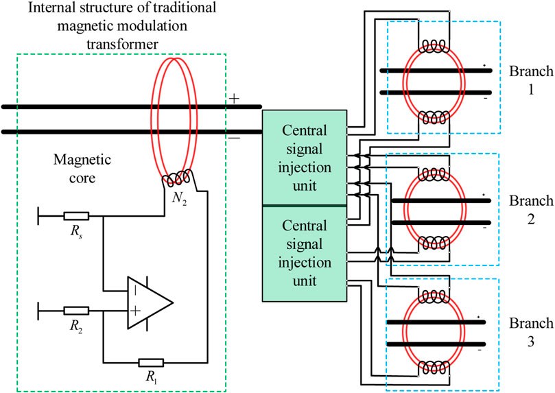
FIGURE 3. Traditional magnetic modulation and improved distributed modulation transformers.
The principle of the transformer is as follows: first, the central processing unit sends out the AC control signal, which is injected into the magnetic ring of the transformer. The acquisition coil transmits the collected signal back to the signal processing module of the central processing unit. Through signal processing, the DC component is extracted (Wang et al., 2020; Li et al., 2015). As shown in Figure 3, when the AC signal is injected into the injection coil on the magnetic ring in the transformer, the AC signal generates an alternating magnetic field in the magnetic ring. The line under test passes through the center of the magnetic core. If the line under test contains a DC signal, the DC signal will generate a magnetic field offset in a fixed direction in the magnetic ring. The acquisition coil collects the signals generated by the combined action of AC and DC signals on the magnetic field, and the injected magnetic field is changed by the bias of the DC magnetic field (Zhao et al., 2012; Chen et al., 2019). The collected signal is processed to obtain the DC current of the line under test. In order to further reduce the cost, the central processing unit of the insulation monitoring system is proposed to inject ac control signals into the transformers of each branch, control the magnetic-modulated current transformer to extract the dc current, and collect the residual current of each branch by the central processing unit so as to judge the insulation decline state. This method does not require the transformer of each branch to install the control circuit, and signal processing and amplification circuit separately and greatly reduces the cost of the transformer; the control signal is uniformly sent by the central processing unit, reducing the error and improving the reliability of insulation monitoring.
The development board of arm STM32F103 selected in this paper is equipped with three 12-bit ADC converters, with an AD sampling rate up to 1 MHz. Because the ADC converter can only collect 0–3.3 V voltage signal and the transformer secondary side current signal is given, we need to regulate the transformer secondary side of current signal, as shown in Figure 4. After current voltage conversion, the in-phase amplifier, pressure limiting protection, signal processing steps, such as isolation, and low pass filtering can be collected to the transformer secondary side current signal, to arm for analysis and calculation.
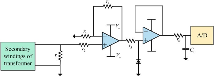
FIGURE 4. Signal conditioning circuit.
2.2.3 Analysis and determination for the insulation fault
In view of the possibility of each cable in the complex DC power system having an insulation drop, the distributed insulation monitoring system can realize the real-time online monitoring of the insulation state of each branch in the system.
Figure 2 shows high-resistance grounding in the DC power supply system. If the grounding fault or insulation degradation occurs in the positive pole of branch 1, there is leakage current I1+, which flows into the earth and flows back to the negative pole through high-resistance grounding of the bus; at this time, the current of branch 1 is increased and
Figure 2 shows Ra and Rb are the high resistance of neutral point grounding bus, communication equipment in the 240V power supply system. The resistance value is generally set to 200 kΩ. Rn+ and Rn− are the positive and negative insulation resistance of the n branch. The cable-related parameters show the system of intact cable insulation resistance of approximately 40 MΩ. Taking branch n as an example, Figure 5 shows the simplified circuit. Ra, Rb, Rn+, and Rn- constitute the bridge balance. When no insulation drop occurs, Rn+ is equal to Rn-, Ra is equal to Rb, and the bridge becomes balanced, and
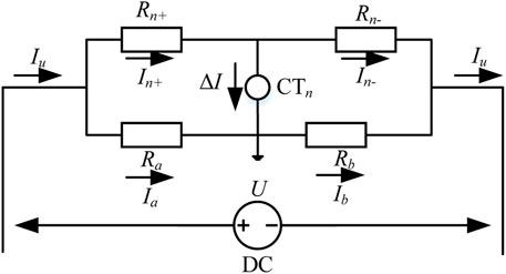
FIGURE 5. Equivalent circuit of the single-pole grounding fault.
When a single-terminal ground fault occurs, the positive insulation resistance Rn+ in branch n decreases, the negative resistance Rn- remains unchanged, and the bridge is unbalanced. The leakage current flows from the positive electrode through the positive insulation resistance Rn+ into the earth and flows back to the negative electrode from the bus high resistance Rb to form a circuit. At this point, the measured current of the branch n CTn is
According to the Kirchhoff’s voltage law (Quintela et al., 2009),
Because the anode voltage U is observed to be 240 V, high-resistance Ra and Rb are 200 kΩ; the drain-current value ∆In is obtained from the transformer CTn, and the value of positive insulation resistance Rn+ can be obtained.
Similarly, if the negative monopole insulation drops, the negative insulation resistance Rn- in the branch n drops, the positive resistance Rn+ remains unchanged, the bridge is unbalanced, and the leakage current flows from the negative electrode through the negative insulation resistance Rn- into the earth and flows from the bus high-resistance Ra back to the positive electrode to form a circuit, which is opposite to the positive insulation decreasing leakage current. At this point, the current measured by CTn in branch n is
Because the anode voltage U is considered to be 240V, high-resistance Ra and Rb are obtained to be 200 kΩ, the leakage current value ∆In is obtained by CTn, by substituting Eq. 5, and the value of negative insulation resistance Rn- can be obtained.
Section 2.1 has been demonstrated that the insulation resistance alarm value should be greater than 28 k.
Therefore, the set values for the insulation monitoring system are
The monitoring principle analysis and formula derivation for the single-terminal grounding fault are mentioned previously. This principle can also be extended to realize the on-line monitoring function for insulation of one or more branches at the same time. It is only necessary to calculate the insulation resistance of each branch individually.
However, in the DC power supply system, in addition to the monopole insulation drop, there are also single-branch double-stage insulation drop faults. Because the aforementioned principles are derived from the monopole insulation drop, it is not applicable to the case of the anode and cathode simultaneous drop. Therefore, the balanced resistance switching principle is adopted in this paper, that is, a resistance switching device is added to the high-resistance connection of the distribution bus to realize the monitoring technology of this kind of fault. Figure 6 shows that a new resistance Rc and switching device are added to the positive pole of the bus. The switching device is selected to be closed every 5 s for a duration of 1 minute before disconnecting. Its simplified equivalent circuit diagram is shown in Figure 6.
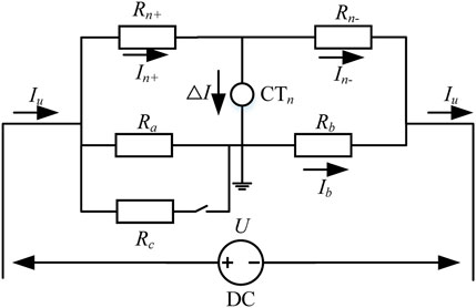
FIGURE 6. Equivalent circuit diagram.
In Figure 6, the initial state of switch K is state 1. Ra and Rb are the high resistances at the neutral point of the bus; Rc is the switchable high resistance, which is used to change the state of the bridge; Rn+ and Rn- are, respectively, the insulation resistance values of positive and negative pole cables in branch n; and ∆In is the leakage current,
If the positive and negative pole wires of branch n suffer from insulation decline at the same time, the equation under state 1 can be obtained according to the following circuit principle:
Combining Eqs 7, 8, we observe that
Switch K is closed, followed by state 2;
Combining Eqs 12, 13, we observe that
Combining Eqs 6, 11, we observe that
Because Ra, Rb, and Rc are known for 200 kΩ, U is the negative voltage on both ends as its value is 240 V, and
Therefore, when the transformer of the branch and the transformer of the high-resistance side of the bus bar detect leakage current, the decrease in the conductor insulation resistance value can be determined in real time, according to the direction and size of the leakage current of the positive and negative branches. If the value is less than the setting value, the system will give an alarm and produce corresponding actions. Compared to the probability that both poles of a branch have an insulation decrease, a single-pole insulation fault is more likely to happen. So, it is necessary to allocate time for monitoring each fault in a reasonable way. Table 1 shows the time allocation for switch K switching to monitor two faults. The resistance switching device is the switch K shown in Figure 2.
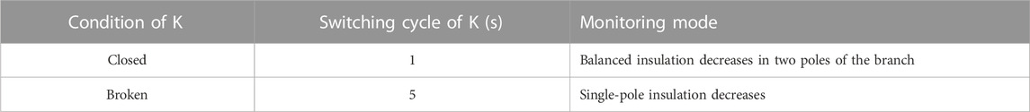
TABLE 1. Time allocation of switch K.
The switching frequency of switch K is 6 s/time. If switch K is closed, the bridge is unbalanced, and the system is efficient to detect the condition that the insulation resistance of the positive and negative poles is decreased to the same value at the same time. Furthermore, if the switch is turned off, a single-pole insulation decrease could be detected in this mode.
3 Results
3.1 Simulation of the single-electrode grounding fault
The Simulink model based on MATLAB is shown in Figure 7.

FIGURE 7. Simulation mode of the distributed insulation monitoring system.
First, the state of the power supply system during normal operation is simulated and analyzed. When the insulation is well, the insulation resistance of each branch is approximately 40 MΩ. The results show that the leakage current measured by each transformer is 0.
The second step is to simulate monopole to ground insulation descent. Branch 1 is set as the faulty branch. In order to ensure the diversity and comprehensiveness of the simulation, it is assumed that the grounding resistance of the branch with an insulation fault is 100 kΩ, 75 kΩ, 50 kΩ, 28 kΩ, and 8 kΩ. When the monopole insulation drops in the positive or negative insulation, the leakage current value is equal, and the current direction is opposite. It can be determined whether the positive insulation or the negative insulation decreases by the current direction. Therefore, only the positive insulation decreases are simulated.
As shown in Figure 8, the comparison between the simulation results and the calculation formula shows the relationship between the leakage current and insulation resistance when different monopole-to-ground insulation resistance values are simulated. The curve in the figure is the formula of calculating insulation resistance by leakage current in Section 2 of this paper.
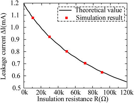
FIGURE 8. Simulation results and the calculation formula.
When the monopole-to-the ground insulation fault occurs, the smaller the monopole-to-the ground insulation resistance is, the greater the leakage current will be. The simulation results are in perfect agreement with the calculated results. Through comparison, it can be seen that the formula proposed in this paper can accurately calculate the insulation resistance for the monopole insulation decline.
If there is insulation degradation in multiple branches at the same time, there will be leakage current in all branches with an insulation fault and the high-resistance grounding bus-bar. Therefore, it could recognize insulation degradation in all branches through this technology.
3.2 Simulation of the multi-electrode grounding fault
In the third step, the insulation of the anode and cathode drops at the same time. In the simulation figure, the branch containing Rc contains a circuit breaker to simulate the two states of bridge resistance before and after switching (before the cut is state 1 and after the cut is state 2). In order to carry out a comprehensive analysis, the following positive and negative insulation resistance values are selected: 150 kΩ, 100 kΩ, 75 kΩ, 50 kΩ, 28 kΩ, and 8 kΩ. Leakage current
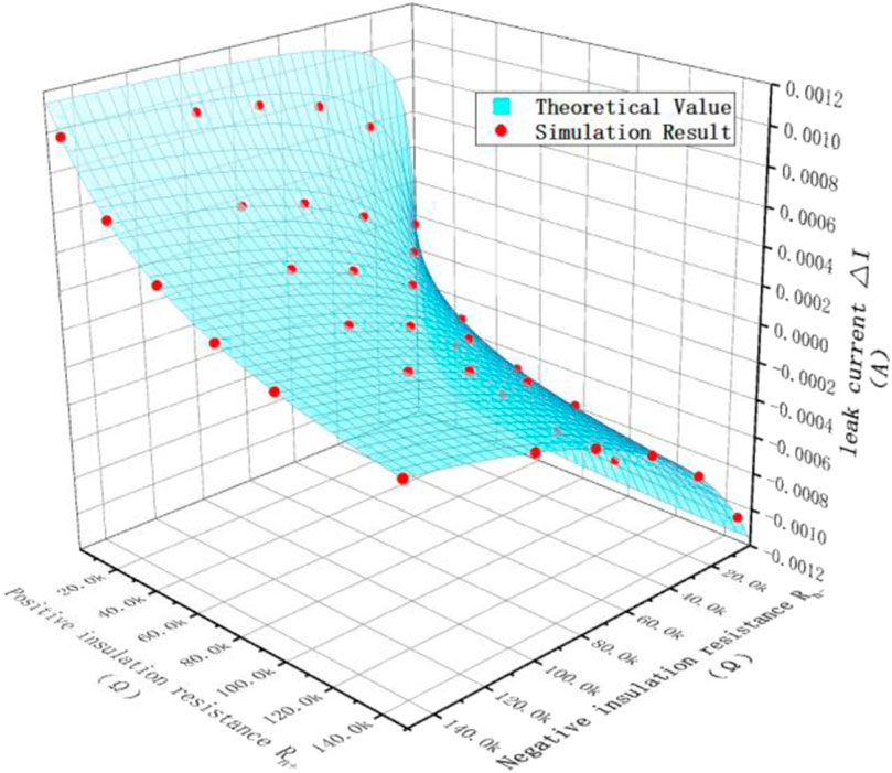
FIGURE 9. Simulation results are compared with the theoretical values under state 1.
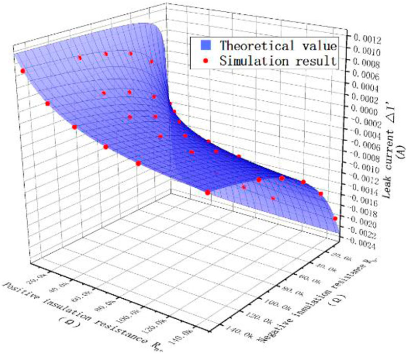
FIGURE 10. Simulation results are compared with the theoretical values under state 2.
In state 1, the greater the difference between the positive electrode-to-ground insulation resistance and the negative electrode-to-ground insulation resistance is, the greater the leakage current value will be, and the direction is related to the insulation resistance at the poles. When
It can be seen from the comparison that the formula proposed in this paper can accurately calculate the insulation resistance of the anode and cathode for the simultaneous decline of the anode and cathode insulation.
3.3 Analysis of the experiment
In order to test the proposed distributed insulation monitoring system in this paper, an experimental setup was built, and a prototype device of the system was made for experiments. Figures 11 and 12 shows the experimental setup of insulation monitoring system proposed in this paper. Eight branches can be collected and calculated simultaneously. Figure 11 shows the central processing module of the system in this paper, whose function is to transmit the detection control signal, process the collected signal, calculate the insulation resistance, and complete the alarm or transmit the result to the upper computer. As shown in Figure 12, the signal acquisition module passes the positive and negative poles of each branch through the center of the current transformer at the same time. The current transformer sends the acquisition signal to the A/D acquisition module of the central processing module and to the oscilloscope used in the experiment. The positive and negative lines of one branch are simultaneously passed through the single-core DC current transformer. The transformer is powered by the central processing module, and the range is
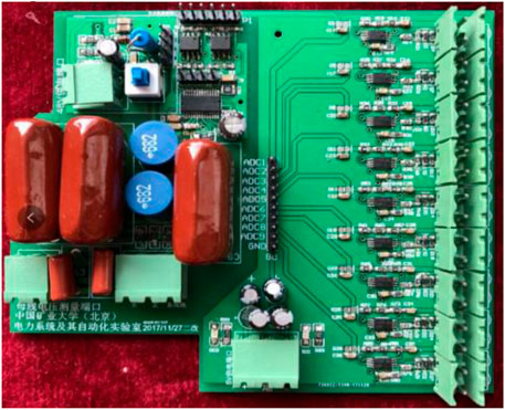
FIGURE 11. Central processing module of the system.
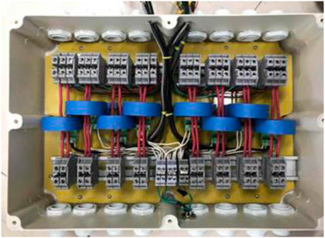
FIGURE 12. Transformer connection situation.
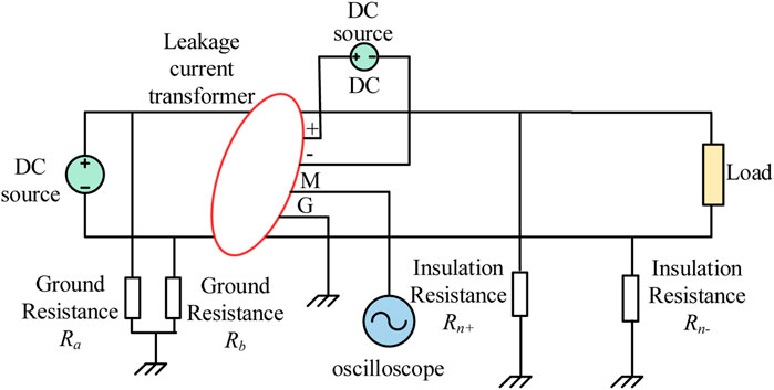
FIGURE 13. Experimental equivalent circuit.
First, the single insulation drop detection was verified. In order to carry out a comprehensive analysis, three branches were selected for the failure test. For each branch, first, the negative insulation resistance was kept unchanged, and the positive electrode was connected to the ground, 100 kΩ, 75 kΩ, 50 kΩ, 28 kΩ, and 8 kΩ. Multiple measurements of leakage current
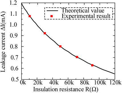
FIGURE 14. Comparison experimental results and theoretical calculation of the single branch.
It can be seen from this that the designed prototype can accurately determine and calculate the single pole-to-ground insulation resistance drop fault.
Then, the condition of positive and negative insulation resistances falling simultaneously was verified, the system bus contained switching resistance Rc, the resistance value of positive and negative insulation resistances to the ground was changed, and the leakage current
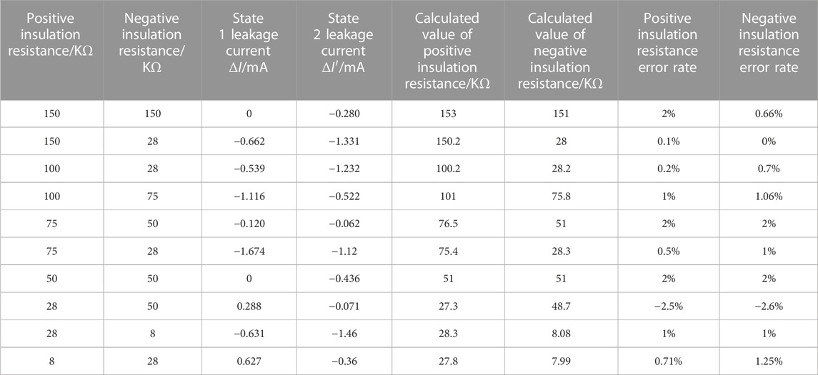
TABLE 2. Simulation and theoretical parameter table of multi-branch cable insulation monitoring.
The comparison between the calculated insulation parameters and the theoretical insulation parameters shows that the monitoring error of the system will gradually increase with the decrease in the difference of positive and negative line insulation resistances. However, the error of insulation resistance calculated by the system based on distributed selection is less than
4 Conclusion
Based on the analysis of the existing problems of the leakage protection technology for DC power supply systems in domestic and abroad, and focus on the insulation degradation fault of the DC power system in the communication station, this paper proposes an on-line insulation monitoring system based on distributed selection. This system can realize online insulation monitoring, and can quickly and accurately diagnose the faulty branch with insulation degradation, single-line grounding fault, and the grounding fault of the remote equipment shell
Through experiments and simulations, the conclusions are as follows:
(1) When the monopole-to-ground insulation drops, the smaller the monopole-to-ground insulation resistance is, the greater the leakage current will be. The simulation and experiment basically agree with the calculation results, which prove that the formula proposed in this paper can calculate the insulation resistance accurately.
(2) When both positive and negative insulation resistances are decreased, in state 1, the larger the difference between the positive pole-to-ground insulation resistance and the negative pole-to-ground insulation resistance is, the larger the leakage current value will be, and the direction is related to the insulation resistance at the poles. When
Data availability statement
The original contributions presented in the study are included in the article/Supplementary Material; further inquiries can be directed to the corresponding author.
Author contributions
CF: methodology and writing—original manuscript. PY: data curation, and writing—review and editing. ZG: resources, supervision, and writing—review and editing. HJ: formal analysis, and writing—review and editing. XZa: investigation, and writing—review and editing. XZh: writing—review and editing.
Funding
The authors declare that no financial support was received for the research, authorship, and/or publication of this article.
Conflict of interest
The authors declare that the research was conducted in the absence of any commercial or financial relationships that could be construed as a potential conflict of interest.
Publisher’s note
All claims expressed in this article are solely those of the authors and do not necessarily represent those of their affiliated organizations, or those of the publisher, the editors, and the reviewers. Any product that may be evaluated in this article, or claim that may be made by its manufacturer, is not guaranteed or endorsed by the publisher.
References
Chen, Y. (2018a). Research on common DC current detection technolog. Low. Volt. Appar. 22, 82–86. doi:10.16628/j.cnki.2095-8188.2018.22.015
Chen, Y., and Sun, J. (2018). Research on residual current protection device with DC component detectio. Electr. Energy Manag. Technol. 14, 37–41. doi:10.16628/j.cnki.2095-8188.2018.14.007
Chen, Z., Li, H., Liu, L., Xiang, L., and Bai, B. (2019). DC bias treatment of hybrid type transformer based on magnetic flux modulation mechanism. IEEE Trans. Magnetics 55 (6), 1–4. doi:10.1109/tmag.2019.2903566
Dawalibi, F. P., Southey, R. D., and Baishiki, R. S. (1990). Validity of conventional approaches for calculating body currents resulting from electric shocks. IEEE Trans. Power Deliv. 5 (2), 613–626. doi:10.1109/61.53063
Hellgren, O. (2004). “A key to expanding older DC systems with new equipment,” in Intelec 2004. 26th annual international telecommunications Energy conference, 241–247. doi:10.1109/INTLEC.2004.1401473
Huang, Y., Qin, J., Liu, N., Huang, H., Zhang, J., Bi, L., et al. (2019). Differential current method of unbalanced bridge with double bridge arm for DC insulation detection. Electr. Energy Manag. Technol. 11, 57–61. doi:10.16628/j.cnki.2095-8188.2019.11.011
Jiang, J., and Ji, H. (2009). “Study of insulation monitoring device for DC system based on four-switch combination,” in 2009 international conference on computational intelligence and software engineering, 1–4. doi:10.1109/CISE.2009.5363460
Li, H. (2012). Application analysis of high voltage DC power supply system (240V) in a test project. Intelec 2012, 1–7. doi:10.1109/INTLEC.2012.6374511
Li, K., Niu, F., Wu, Y., Wang, Y., Dai, Y., Wang, L., et al. (2015). Nonlinear current detection based on magnetic modulation technology. IEEE Trans. Magnetics 51 (11), 1–4. Art no. 4004804. doi:10.1109/tmag.2015.2446134
Luo, Z., Ren, X., Yang, H., Cai, G., Qing, C., and Luo, Y. (2016). “Research on the insulation monitoring devices for DC power system based on the detection technology of DC bus to grounding capacitance,” in 2015 2nd international forum on electrical engineering and automation, 117–120. doi:10.2991/ifeea-15.2016.24
Olszowiec, P. (2017). Influence of insulation monitoring devices on the operation of DC control circuits. Power Technol. Engineeing 6 (50), 653–656. doi:10.1007/s10749-017-0768-1
Quintela, F. R., Redondo, R. C., Melchor, N. R., and Redondo, M. (2009). A general approach to Kirchhoff's Laws. IEEE Trans. Educ. 52 (2), 273–278. doi:10.1109/te.2008.928189
Roberts, D. (2009). 50-V shock hazard threshold. IEEE Trans. Industry Appl. 46 (1), 102–107. doi:10.1109/TIA.2009.2036541
Rybski, R., Kaczmarek, J., and Kontorski, K. (2015). Impedance comparison using unbalanced bridge with digital sine wave voltage sources. IEEE Trans. Instrum. Meas. 64 (12), 3380–3386. doi:10.1109/TIM.2015.2444255
Shi, M., Miao, H., Fei, J., Ge, X., Xiao, X., Wu, F., et al. (2022). “The development of DC leakage current monitoring device,” in 2022 IEEE 5th international electrical and Energy conference (CIEEC) (Nangjing, China: IEEE).
Wang, S., Li, H., Liu, Q., Huang, Q., and Liu, Y. (2020). “Design of a DC residual current sensor based on the improved DC component method,” in 2020 IEEE power & Energy society general meeting (PESGM) (Canada: Montreal, QC), 1–5.
Xie, Z., Han, S., and Wang, L. (2016). “The magnetic modulation of DC transformer core characteristics analysis,” in 2016 3rd international conference on information science and control engineering (ICISCE), 1433–1438. doi:10.1109/ICISCE.2016.306
Yin, G., Liu, Y., Xu, H., Li, M., and Li, J. (2012). “The new DC system insulation monitoring device based on phase differences of magnetic modulation,” in 2012 international conference on systems and informatics (ICSAI2012), 585–658. doi:10.1109/ICSAI.2012.6223065
Yow-Chyi, L., and Chen-You, L. (2012). Insulation fault detection circuit for ungrounded DC power supply systems. SENSORS 2012, 1–4. doi:10.1109/ICSENS.2012.6411550
Zhao, H., Xiao, X., and Sun, Q. (2017). Identifying electric shock in the human body via α dispersion. IEEE Trans. Power Deliv. 33 (3), 1107–1114. doi:10.1109/TPWRD.2017.276616
Zhao, X., Li, L., Lu, J., Cheng, Z., and Lu, T. (2012). Characteristics analysis of the square laminated core under DC-biased magnetization by the fixed-point harmonic-balanced FEM. IEEE Trans. magnetics 48 (2), 747–750. doi:10.1109/tmag.2011.2174776
Zhenbin, C., Weiya, C., Xiangyu, C., Qiao, H., Lu, H., and Qiu, N. (2021). A new method of insulation detection on electric vehicles based on a variable forgetting factor recursive least squares algorithm. IEEE Access 9, 73590–73607. doi:10.1109/access.2021.3079332
Nomenclature

Keywords: insulation monitoring system, leakage phenomenon, fault line selection, grounding selection for DC system, simulation and prototype experiments
Citation: Feng C, Ye P, Gao Z, Jiang H, Zang X and Zhang X (2023) A novel distributing–collecting on-line insulation monitoring system and line selection technology for the DC supply system. Front. Energy Res. 11:1291552. doi: 10.3389/fenrg.2023.1291552
Received: 09 September 2023; Accepted: 09 October 2023;
Published: 24 October 2023.
Edited by:
Rashid Mehmood, King Abdulaziz University, Saudi ArabiaReviewed by:
Zhixuan Gao, China Electric Power Research Institute (CEPRI), ChinaZecheng Li, State Grid Ningxia Electric Power Research Institute, China
Peng Chen, Huairou Laboratory, China
Copyright © 2023 Feng, Ye, Gao, Jiang, Zang and Zhang. This is an open-access article distributed under the terms of the Creative Commons Attribution License (CC BY). The use, distribution or reproduction in other forums is permitted, provided the original author(s) and the copyright owner(s) are credited and that the original publication in this journal is cited, in accordance with accepted academic practice. No use, distribution or reproduction is permitted which does not comply with these terms.
*Correspondence: Zhengzhong Gao, c2tkZ3p6QDE2My5jb20=