 B. Varun Kumar1
 P. Rajesh Kanna
 Jan Taler
95% of researchers rate our articles as excellent or good
Learn more about the work of our research integrity team to safeguard the quality of each article we publish.
Find out more
ORIGINAL RESEARCH article
Front. Energy Res. , 28 November 2023
Sec. Solar Energy
Volume 11 - 2023 | https://doi.org/10.3389/fenrg.2023.1279225
Solar air heating thermal systems have found extensive utilization in a broad array of industrial and residential settings, playing a pivotal role in the conversion and reclamation of solar energy. Implementing repeated artificial roughness in the surfaces has the potential to augment thermal performance in solar air heaters (SAHs). This study presents a numerical investigation of SAHs with artificial rough surfaces, consisting of polygonal-shaped ribs and grooves located at different places inside the rectangular duct, that improve thermal efficiency. ANSYS Fluent software was employed to simulate the SAH with different relative pitch distances of p = 10 mm and 20 mm and relative rib heights e/d = 0.09–0.045. The working fluid air flows at different Reynolds numbers (Re), ranging from 3,800 to 18,000. Nusselt number (Nu), friction factor (f), and Thermal Hydraulic Performance (THP) are parameters to evaluate the performance of the SAH. The renormalized group (RNG) k-ϵ turbulent model was implemented in this simulation. The study outcomes indicate that increasing the rib height improves the heat transfer rate and nonetheless increases pressure drop while increasing the pitch distance. The higher Nusselt number (Nu) is 3.762 attained at p = 10 mm and 3.420 at p = 20 mm in the center-positioned rib at Re 3,800. The lower friction factor (ƒ) obtained in p = 20 mm is 1.681 and 0.785 in p = 10 mm in the staggered positioned rib at higher Re 15,000. The optimal THP was achieved at 2.813 at a staggered rib height at a pitch distance of p = 10 mm at Re 8,000. The study’s findings suggest that the incorporation of artificial rough surfaces has the potential to enhance the THP of an SAH.
A solar air heater (SAH) is a device that harnesses the abundant solar energy available worldwide for various applications, including space heating, textile, and chemical industries. However, the conventional SAH suffers from lower thermal performances due to poor thermal convection between the working fluid air and the surface of an absorber plate. In recent decades, researchers have explored the use of artificial roughness in the absorber plate surfaces in augmenting heat transfer in the SAH. The implementation of rough surfaces in absorber plates is achieved by introducing ribs or protrusions of different shapes and sizes. Some of the significant outcomes of these numerical and experimental investigations include an increase in heat transfer rates, a decrease in pressure drops, and improved thermal performance of the SAH (Promvonge and Thianpong, 2008; Promvonge et al., 2012). Various rib and groove shapes have been selected in the investigation to attain better heat transfer rates, including rectangular (Eiamsa-ard and Promvonge, 2008), circular (Kumar et al., 2009), triangular (Eiamsa-ard and Promvonge, 2009), trapezoidal, and serrated ribs (Sripattanapipat and Promvonge, 2009) at Reynolds numbers ranging from Re 3,000 to Re 18,000. Among them, rectangular and circular rib shapes are the most commonly investigated due to their ease of manufacturing and the availability of experimental data. The absorber plate efficiency of the SAH is enhanced using various rib shapes, such as a transverse wire rib producing a maximum THP of 1.85 at Reynolds number ranging from Re 3,800 to Re 18,000 (Verma and Prasad, 2000), an arc-shaped wire rib producing a THP of 1.70 at Reynolds number ranging from Re 3,800 to Re 18,000 (Saini and Saini, 2008), an inverted U-shape rib producing a THP of 1.82 at Reynolds number ranging from Re 3,800 to Re 18,000 (Bopche and Tandale, 2009), a dimple-shaped rib attaining a THP of 1.77 at Reynolds number ranging from Re 3,800 to Re 18,000 (Saini and Verma, 2008), and a W-shaped rib producing a maximum THP of 1.87 at Reynolds number ranging from Re 3,800 to Re 18,000 (Kumar et al., 2009). These ribs are incorporated to advance the THP of the SAH. Research conducted by the authors demonstrates that the THP ranging from 1.72 to 1.87 has been achieved, with the maximum heat transfer rate obtained at an attack angle of 90o.
Several rib shapes have been explored by researchers to enhance the THP. Gawande et al. (2016) used an L-shaped rib that yielded a maximum THP of 1.90, and Yadaba Mahanand (Mahanand and Ranjan Senapati, 2020) used an inverse T-shaped rib resulting in a higher THP of 1.87. A novel shape was articulated (Singh Yadav and Bhagoria, 2013) through a detailed examination of circular ribs through analytical means. Variations in height and pitch distance were performed, which resulted in an exceptional thermal enhancement, surpassing that of the smooth duct by a factor of 1.65. Yadaba Mahanand (Mahanand and Senapati, 2021) used a quarter circular rib in the SAH and observed that the Nu increased with increasing Reynolds number, while the ƒ increased with increasing rib pitch and a maximum value of THP was attained (1.88).
Pa et al. (2016) studied multiple arc-shaped rib configurations with varying gap settings and rib arc angles, ranging between 30o and 75o. Their study revealed that the Nu was 5.85 times greater than that of the smooth duct. Similarly, Varshney and Gupta (2017) studied the tapered shape of ribs in rectangular ducts, and their results showed that the use of ribs enhanced heat transfer significantly. Ribs with angles ranging between 1.6o and 3.2o and varying pitch distances from 10 mm to 25 mm were examined. The report unveiled that, at a Reynolds number of 12,000, an inclination of 1.6° resulted in the most significant thermal enhancement. In another study, Varun Kumar et al. (2018) investigated the influence of ribs in the SAH, and they found the thermal efficiency in the SAH to be augmented significantly, utilizing diverse shapes and placements. It was found that the polygonal-shaped rib with minimum pitch distance yields higher thermal performances than ribs of other shapes and pitch distances. Singh Yadav et al. (2022a) took a semi-circular rough surface for enhancement of THP at a relative pitch distance of 5–25 at Re 3,800 to Re 18,000. Researchers revealed that a maximum THP value of 1.98 had been obtained at Re 15,000. Singh Yadav et al. (2022b) presented a detailed overview of various rough surfaces with different pitch distances, rib height in Reynolds number ranging from 2000 to Re 20,000, and their thermal enhancement in different applications. Arya et al. (2023) investigated V, arc, and transverse broken shape of the rib at various attack angles of 45°–75°, pitch distance of 15–25, relative roughness height 0.024–0.036, and relative wire length of 0.14–0.2. The analytical report presented that attack angles of 45° produced higher thermal performances at Re 8,750, and the THP is 1.63. Rajesh Maithan et al. (2023) conducted an exergy analysis in the SHC using delta winglets at various attack angles in Re ranging from 4,000 to 18,000. The researchers reported that an angle of 60° achieved 29.88% exergy efficiency at a pitch distance of 5. Kumar et al. (2023) proposed a new design NACA 0020 to enhance the THP at p = 13 and roughness height 0.06 at Re ranging from 6,000 to 18,000. The result revealed that a maximum THP of 2.21 was attained at Re 6,000. Alam and Kim (2017) investigated the conical protrusion rib at a relative pitch distance of 6–12 and relative height of 0.020–0.044 at Re 4,000 to 16,000. The researchers reported extreme thermal efficiency achieved at 69.8% and recorded an efficiency enhancement factor of 1.346%. Alam and Kim, (2016) took a semi-elliptical rough surface with an attack angle of 30°–90° and positioned it in an inline and staggered technique at Re 6,000 to Re 18,000 to achieve higher THP. The results show that an attack angle of 75° produced higher Nu and ƒ of 2.05 and 6.93 for inline and 1.73 and 6.12 for staggered arrangement, respectively. Singh et al. (2023) investigated an S-shaped dimpled rib surface to augment the THP in the SAH. The result revealed that Nu was 3.55 times and ƒ 2.81 to 4.54 times greater than that of a smooth surface and the maximum THP achieved was 2.15.
The literature demonstrates a wide range of strategies employed to improve the thermal efficiency of the SAH, with a particular focus on the use of various rib and groove shapes. The studies have used different rib shapes, such as rectangular, inclined trapezoidal, serrated, semicircular, and helical, and have reported significant improvements in the heat transfer characteristics in the SAH by varying the rib pitch distance, rib height, and rib positioning angle. However, despite the extensive research in this area, there is still a research gap that needs to be addressed. Specifically, there is a lack of comparing rib positioning on both sides of the wall in the inline and staggered arrangement. Moreover, ribs placed in the center of the duct were not compared with those observed in earlier research. Therefore, further research is needed to compare the effectiveness of ribs placed in different parts of SAHs and their ability to enhance heat transfer and minimize pressure drop in SAHs. Such studies can help identify the most suitable rib shape for a given application and optimize the design of SAHs for extreme performance.
The main aim of the research work is as follows:
1. Explore the impact of relative roughness pitch and position of ribs on the average heat transfer and flow friction characteristics.
2. Optimize artificial roughness and flow parameters to improve the thermal performance of an artificially roughened SAH while maintaining a constant pumping power requirement.
The investigation methodology comprised three steps. First, the smooth surface of the SAH was studied by varying the entry flow velocity based on the Re to investigate the augmentation of the Nusselt number (Nu) and friction factor (f). Second, the proposed test section employed rough surfaces individually, by changing pitch distances, and THP and pressure drop are measured. Third, the results obtained were compared to determine the heat transfer enhancement achieved by the application of rough surfaces.
Figure 1 illustrates a schematic layout of the SAH, while Figure 1. (ii) displays the proposed geometries for the b) polygonal rib in an inclined position, c) polygonal rib in a staggered position, d) polygonal rib and groove, and e) polygonal rib at the center of the rectangular duct. The rectangular duct of the SAH shown in Figure 1 (i) has dimensions of 640 mm in length (245 mm for the entry section—L1, 280 mm for the test section—L2, and 115 mm for the exit section—L3) with a height (H) and width (W) of 20 mm and 100 mm, respectively, as described in Varun Kumar et al. (2021). The proposed geometry with their various positions are presented in detail in Figure 2. Furthermore, the rib arrangement is outlined in Table 1. Figure 3 demonstrates the position of the polygonal rib and groove in a rectangular shape at varying pitch distances of p = 10 mm and p = 20 mm, and sharp edges with tilted profiles of the rib, which were selected to disrupt the fluid flow and maximize the turbulence in the flow region of laminar sub-layer to enhance heat transfer. To avoid unnecessary complexity, the present computational fluid dynamics (CFD) investigation followed certain assumptions.
a. The flow considered in this study is steady state, turbulent, and incompressible (Varun Kumar et al., 2021).
b. The flow fluid is air, which enters the duct at atmospheric conditions. The properties of air are listed in Table 2.
c. A no-slip condition is applied to the bottom and sidewall of the duct.
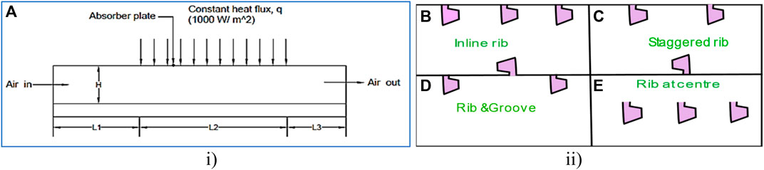
FIGURE 1. Schematic layout of the i) SAH and ii) proposed polygonal rib with various positions in an absorber plate. (A) SAH, (B) inline rib, (C) staggered rib, (D) rib and groove, and (E) rib at the center.
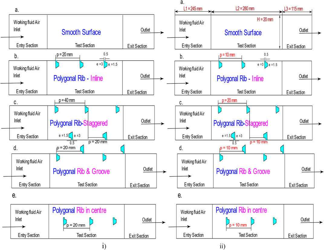
FIGURE 2. Schematic layout of the SAH with the polygonal rib placed at various positions at i) p = 20 mm, ii) p = 10 mm. (A) Smooth surface, (B) inline rib, (C) staggered rib, (D) rib and groove, and (E) rib at the center.

TABLE 1. Arrangement of artificial roughness.
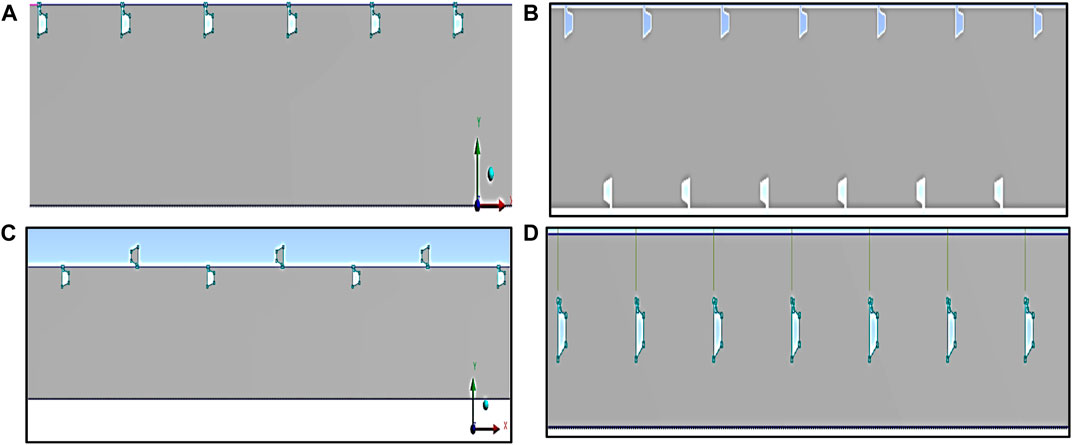
FIGURE 3. Geometry of polygonal shapes of rib position at pitch distance p = 20 mm. (A) Inline, (B) staggered, (C) rib and groove, and (D) center.
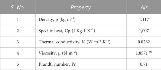
TABLE 2. Present study—(air) working fluid—(thermo-physical property) (Varun Kumar et al., 2021).
To ensure accurate results for the proposed geometry, a grid-independent study is needed to be conducted using ANSYS Fluent version 13.0. In this study, the element sizes were varied between 0.4 mm and 0.2 mm, and four different values were used to identify the appropriate element cell size for the analysis. The computed values for Nu and ƒ were closer to acceptable results when using an element cell size of 0.2 mm than the previously used element cell size (Varun Kumar et al., 2021). Figure 4A,B demonstrate the variation in the grid element size and node count on a smooth surface of an SAH and shows how the change in grid size affects a smooth surface in the SAH, while Figure 5 shows the mesh generated for the polygonal rib positioned at a) inline, b) staggered, c) rib and groove, and d) center placed at a pitch distance of p = 20 mm. Creation of a non-uniform mesh in the shape of a tetrahedron grid and convergence was taken between 114,565 and 1 52,145 element cells, depending on the proposed element size (Varun Kumar et al., 2021), and the details are presented in Table 3. In addition to CFD simulations, the y + values are crucial for assessing result accuracy, particularly in the context of near-wall flow behavior. In the current simulation, the y + value achieved was 0.1993, which is a strong indicator that the simulation is accurately capturing the details of flow near surfaces or walls. This low y + value suggests that the mesh resolution near the walls is sufficient to model the boundary layer and viscous effects with precision. In essence, a y + value of 0.1993 signifies that the simulation’s near-wall predictions are reliable and trustworthy. The maximum deviation in Nu was observed in the 152,145 element cells, while the average Nu ranges showed the least deviation of +1.50%. Therefore, 152,145 element cells were used for the analytical investigation.
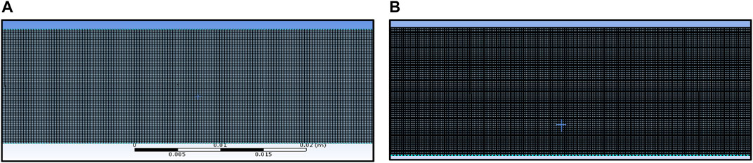
FIGURE 4. Smooth surface of the SAH and their element size ranges are (A) 114,210 and (B) 145,925.
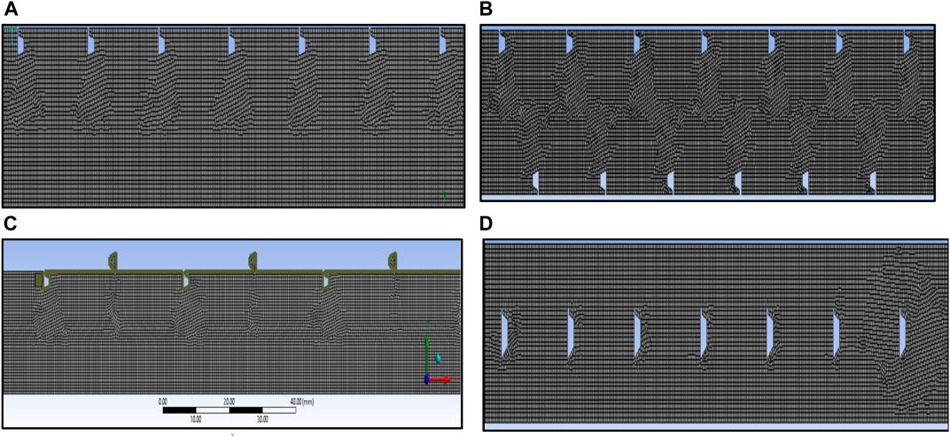
FIGURE 5. Meshing of polygonal shapes of rib position at pitch distance p = 20 mm. (A) inline, (B) staggered, (C) rib and groove, and (D) center.
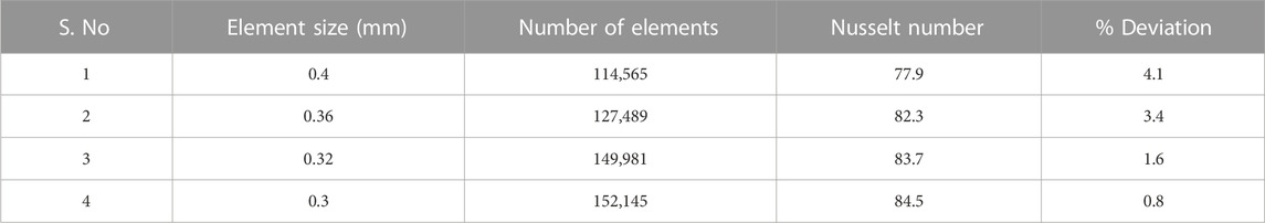
TABLE 3. Grid-independent study.
The examination of heat transfer within a working fluid in an SAH incorporating a rough surface in simulations involves the application of the following formulated steady-state 2D continuity, momentum, and energy equations (Varun Kumar et al., 2021):
Mass conservation or continuity equation:
Momentum conservation or Navier–Stokes equation:
Energy conservation equation:
Additionally, non-dimensional flow parameters are assessed using the following equation:
i)
ii) The friction factor was computed using the following equation…
It is essential to study the heat transfer and pressure drop characteristics of the SAH through THP. The THP with constant pumping, as referenced in Webb and Eckert (1972), is determined by the following equation:
THP parameter:
i) Nur represents the Nu in a rough surface
ii) Nus represents an Nu for a smooth surface and was taken from the Dittus–Boelter equation (McAdams, 1942; Taler and January, 2017):
The Reynolds number varies from 3,800 to 18,000 (Varun Kumar et al., 2021), and the Prandtl number (Pr) of the working fluid air = 0.71 Table 2.
i) fr represents the friction factor for rough surfaces.
ii) fs represents a friction factor for the smooth surface of an SAH, obtainable from the Blasius equation (McAdams, 1942)
Validating turbulent models is crucial for accurately predicting thermal performance enhancement in computational exercises. This research validates the average Nusselt number for a smooth surface by employing empirical equations such as Dittus–Boelter (9) and Taler (10), in conjunction with various turbulence models:
a) Standard k-ε epsilon,
b) RNG k-ε epsilon,
c) Realizable k-ε epsilon,
d) Standard k-ω omega, and
e) SST k-ω omega.
The study outcomes are compared and visually presented in Figure 6. The renormalization k-ε epsilon model is found to have the closest Nu values to the empirical correlation, with only a + 0.35% deviation. As a result, the RNG k-ε epsilon model is preferred for simulating the SAH in this research, consistent with similar studies by other researchers (Taler and January, 2017; Varun Kumar et al., 2021).
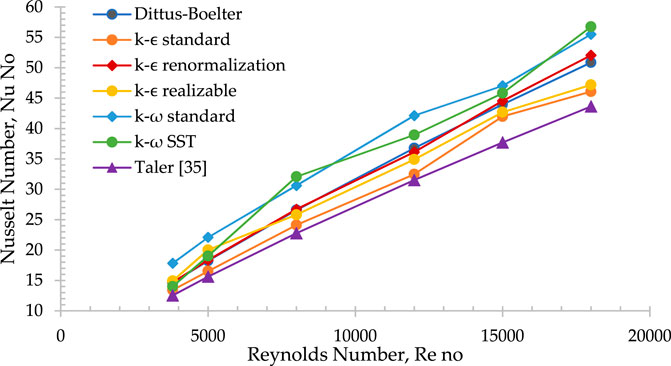
FIGURE 6. Comparative analysis of Nusselt number (Nu) employing various turbulent models in contrast to the empirical Eq. 9.
The renormalized group (RNG) k-ϵ model incorporates the following equation to investigate the impact of small-scale turbulence adjacent to the rough surface (rib) and wall surface in the direction of the fluid stream (Varun Kumar et al., 2021).
and
The term Pk denotes the production of turbulent kinematic energy resulting from the velocity gradient and serves as an indicator of turbulence intensity.
i)
In this context, the turbulent viscosity represented by μt is calculated by combining k and ε in the following manner:
Turbulent model RNG k-
In the present study, ANSYS Fluent version 13.0 was used to employ the finite volume method (FVM). The governing equations of continuity, momentum, and energy were solved by designing artificial roughness, generating the grid, and ensuring solution convergence. The specified Reynolds numbers, as listed in Table 4, were used to set the boundary conditions for the inlet velocity magnitude, while a constant heat flux of 1000 W/m2 was applied to the upper wall surface in the test section and the outer surface of the polygonal rib as solar radiation. Atmospheric conditions were set as the outlet pressure. The pressure–velocity coupling in the simulation utilized a SIMPLE algorithm, and a second-order double-precision was opted for the computations. Second-order discretization was applied to all transport equations. Criteria for continuity, x-velocity, and y-velocity were set at 10−6 to ensure accurate results during residual monitoring (Varun Kumar et al., 2021). The standard initialization method was employed for computing all zones. In the calculation part, the number of iterations and reporting intervals were adjusted depending on the rib placement within the duct. After achieving convergence, the average Nusselt number (Nu) and average friction factor (f) values were compared with empirical Equations (9, 10, and 11) to assess thermal enhancement.
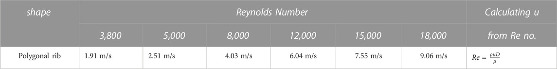
TABLE 4. Inlet velocity taken from Reynolds number (Varun Kumar et al., 2021).
In our current study, we have conducted a comparative analysis of the smooth surface analytical data concerning average Nu and ƒ characteristics. We compared our findings with significant results from both numerical and experimental investigations. Those of Singh Yadav and Bhagoria (2013), Gawande et al. (2016), and Mahanand and Ranjan Senapati (2020) are a few investigations that are similar to ours that are presented in Figure 7.
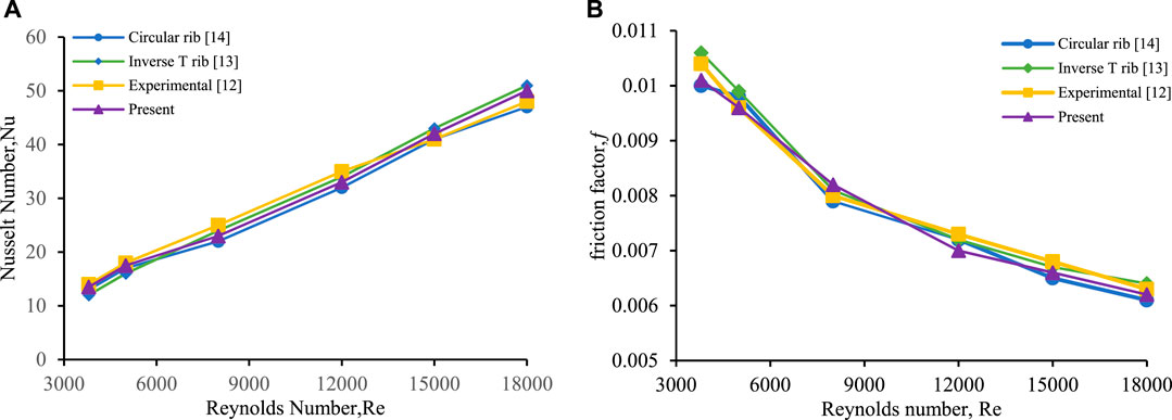
FIGURE 7. Evaluation of (A) Nu and (B) ƒ with Re no. for a smooth surface with previous reported values.
Our observations indicate that the Nu values exhibit the least variation in the data presented by Singh Yadav and Bhagoria (2013); Gawande et al. (2016), with the maximum deviation being limited to +5% in the case of Mahanand and Ranjan Senapati (2020). Additionally, the friction factor (f) data display a minimal variance in the values obtained from Mahanand and Ranjan Senapati, (2020). This outcome instills confidence in our research, encouraging further exploration of the proposed geometric parameters.
This numerical analysis investigates the mean Nu, ƒ, and THP of the projected rough surface rib by varying the relative roughness pitch p = 10 mm and p = 20 mm, and the relative roughness height e/D = 0.9 performance of the rib shapes is evaluated by contrasting them with established outcomes from published studies to determine the extent of thermal augmentation.
Figure 8 shows the Nusselt number for the proposed rib shapes in the SAH, indicating a continuous increase in the Nu with the Reynolds number for all rough ribs due to forced convection. Additionally, the rib configuration induces a vortex that disrupts the secondary layer of the flow region, leading to improved heat transfer. As the Reynolds number increases, the length of recirculation in the rectangular duct decreases, thereby enhancing thermal performance. Among the rib shapes, the staggered polygonal rib at Re = 18,000 for p = 20 mm and center rib for p = 10 mm significantly increase the heat transfer rate primarily due to the formation of eddies near the ribs positioned in opposite directions, which were closer to the laminar sub-layer on both sides of the wall, and closer pitch distances in the center rib produced greater heat transfer than others.
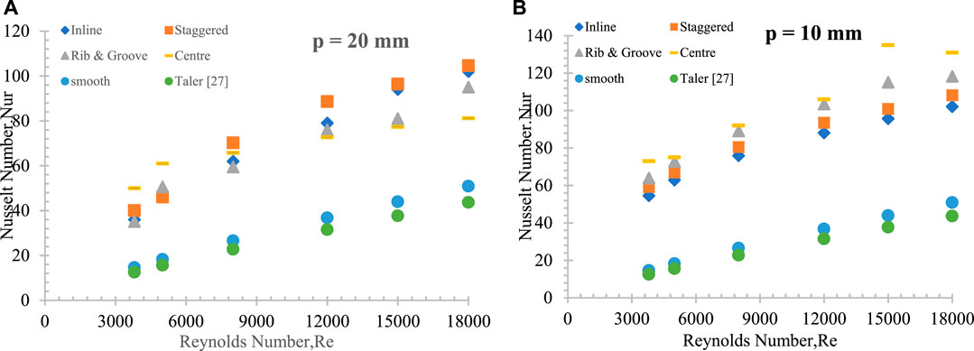
FIGURE 8. Nu variation with Reynolds number for different positions of the rib at relative pitch distance (A) p = 20 mm and (B) p = 10 mm.
It was observed that the vortex size near the initial set of ribs closest to the boundary-wall surface was gradually expanding while boosting the Reynolds number. This expansion results in enhanced local convective heat transfer, as indicated by the contour plots of TKE in Figure 9 and Figure 10. These plots are based on relative pitch distances of p = 20 mm and p = 10 mm, with the Reynolds number ranging from 3,000 to 18,000. In the first scenario (case 1), ribs positioned inline lead to the development of strong turbulence originating from the first pair of ribs. These turbulent effects intensify as they propagate downward. For the second scenario (case 2), which involves rib and groove configurations, a high level of circulation is generated when p = 10 mm, while a robust vortex forms at p = 20 mm. In the third case (case 3), which features staggered rib positioning, vortices are generated on both sides of the laminar surface close to the wall. A substantial circulation is observed at higher Reynolds numbers (Re = 18,000) in the upper wall region, while lower Reynolds numbers (Re = 3,800) result in circulation on the bottom wall. Both the entry and exit regions are depicted in Figure 9 and Figure 10. In the fourth case (case 4), where ribs are positioned at the center, strong turbulence is generated at lower Reynolds number, and minimal turbulence occurs at higher Reynolds number.
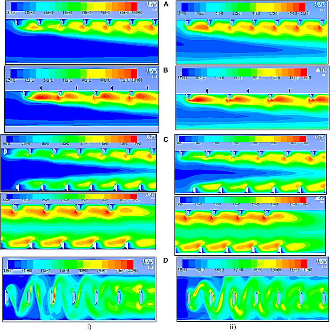
FIGURE 9. Contour plot of TKE at p = 20 mm in the polygonal rib at a Reynolds number of (i) 18,000 (ii) 3,800. (A) Inline, (B) staggered, (C) rib and groove (entry and exit of the test section), and (D) rib at the center.
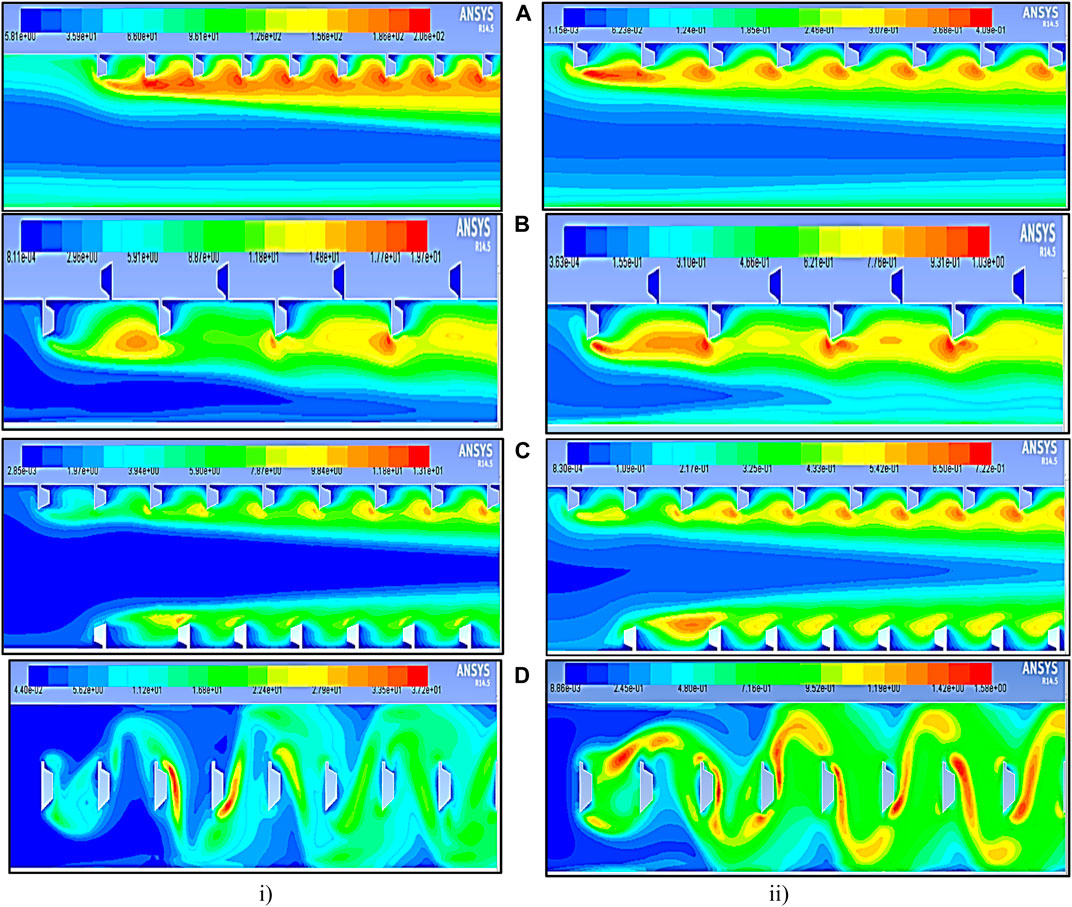
FIGURE 10. Contour plot of TKE at p = 10 mm in the polygonal rib at a Reynolds number of (i) 18,000 and (ii) 3,800 (A) Inline, (B) staggered, (C) rib and groove, and (D) rib at the center.
The fluid flow velocity and their contour plot results in Figure 11 and Figure 12 demonstrate that increasing inlet velocity results in higher turbulent intensity, causing stronger vortices near the staggered and center-positioned rib at a relative roughness pitch of 10 mm compared to 20 mm shown in Figure 11 and Figure 12 (c-entry and exit of the test section). This results in more robust turbulence and increased heat energy transfer as the Reynolds number increases in the SAH.
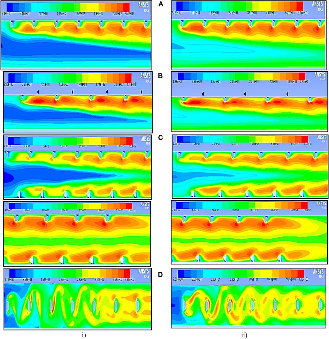
FIGURE 11. Contour plot of I at relative pitch distances p = 20 mm in the polygonal rib at a Reynolds number of i) 18,000 and ii) 3,800. (A) Inline, (B) staggered, (C) rib and groove (entry & exit of test section), and (D) rib at the center.
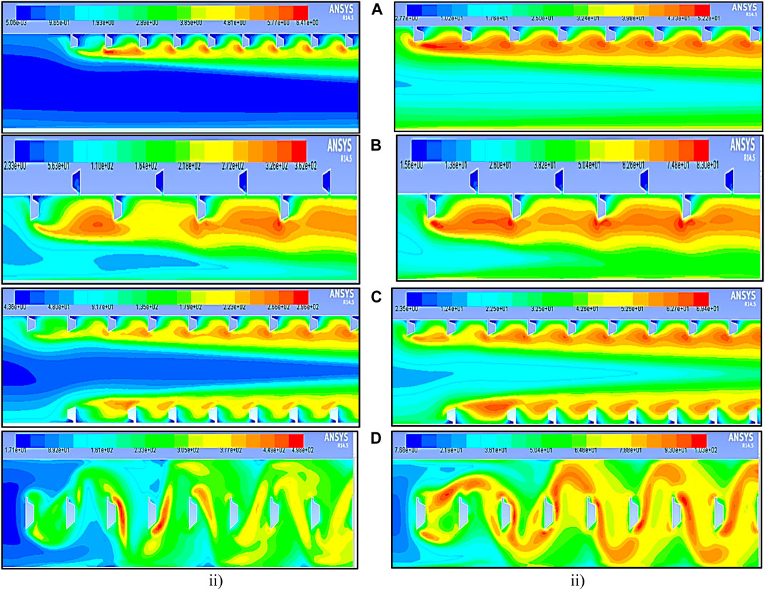
FIGURE 12. Contour plot of I at relative pitch distances p = 10 mm in the polygonal rib at a Reynolds number of (i) 18,000 and (ii) 3,800. (A) Inline, (B) staggered, (C) rib and groove, and (D) rib at the center.
The pronounced interaction between the initial pair of ribs amplifies the average Nusselt number along the streamwise distribution. Figure 8 provides the Nu enhancement ratio for the suggested rib configuration, with the highest Nu/Nus ratio of 3.76 observed for the polygonal-shaped rib located at the center with a relative pitch distance of p = 10 mm and at a Re 3,800.
The fluid flow velocity contour plot in Figure 13 and Figure 14 at p = 20 mm and p = 10 mm clearly illustrates the influence of various polygonal-shaped ribs on the absorber plate of the SAH. It indicates that the size of the circulation generated in the flow direction is larger for the envisaged rib shapes at closer relative pitch distances of p = 10 mm at a Reynolds number of 18,000. This phenomenon is linked to the impact of the rib’s apex edge shape, which is then accompanied by a subsequent change in the rib’s orientation. This combination creates a strong vortex in the vicinity of the initial rib. This induces strong turbulence near the wall surface in the flow direction, leading to a higher heat transfer rate. Furthermore, it was observed from all rib shapes that the center polygonal rib had a more significant impact than other ribs at both pitch distances, as shown in Figure 13 and Figure 14. (ii) This observation suggests that the average Nu increases with increasing Reynolds number, primarily because higher Reynolds numbers lead to increased recirculation in the fluid flow direction, thereby resulting in a higher convective heat transfer coefficient.
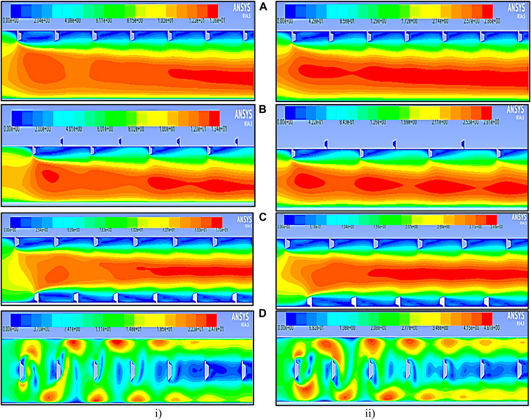
FIGURE 13. Contour plot of velocity at relative pitch distance p = 20 mm in the polygonal rib at a Reynolds number of (i) 18,000 and (ii) 3,800. (A) Inline, (B) staggered, (C) rib and groove, and (D) rib at the center.
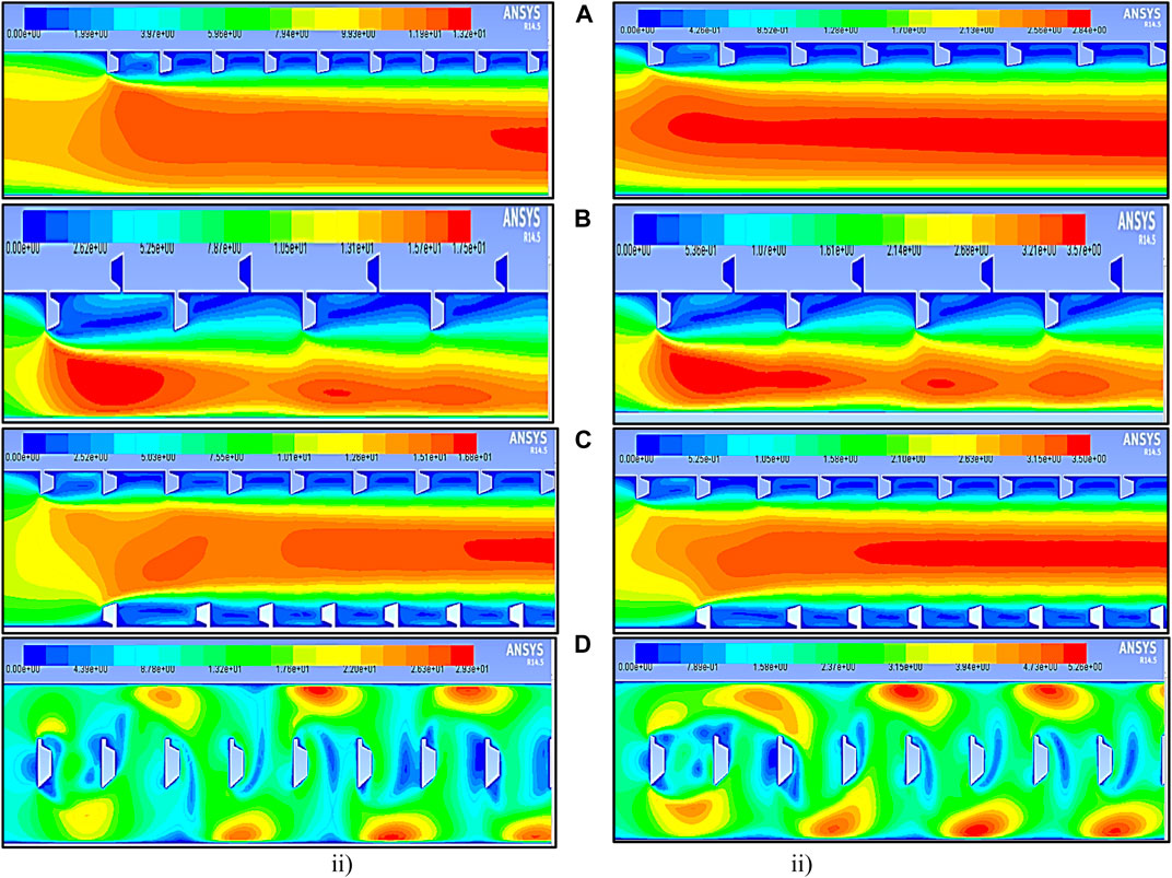
FIGURE 14. Contour plot of velocity at relative pitch distance p = 10 mm in the polygonal rib at a Reynolds number of (i) 18,000 and (ii) 3,800. (A) Inline, (B) staggered, (C) rib and groove, and (D) rib at the center.
Implementing a rough surface in the SAH may lead to extra friction losses compared to a smooth surface, but it is crucial to examine the hydraulic (heat transfer) performances in the SAH to achieve a better heat transfer rate. For maintaining a balance in pressure drop within a duct across different Re values, a constant pumping power is necessary. Figures 15A,B illustrate the ƒ characteristics for dissimilar polygonal rib shapes with relative roughness pitch p = 20 mm and p = 10 mm in varying Reynolds numbers. It can be inferred that the staggered positioned rib has a record least average ƒ, as shown in Figure 15. The findings suggest that the average ƒ decreases as the Reynolds number increases, which is attributed to the conquest of the viscous region of the sub-layer in a fully developed turbulent flow. The staggered polygonal-shaped rib, due to the intermission in the flow path caused by the enhanced relative roughness height of the rib, produces lower ƒ. In addition, it is observed that greater pitch distances lead to a reduction in the average friction factor, especially at the maximum Reynolds number of 18,000. From the depicted data, it can be inferred that the average ƒ decreases as the pitch distance increases, as well as when the relative roughness height of the rib increases.
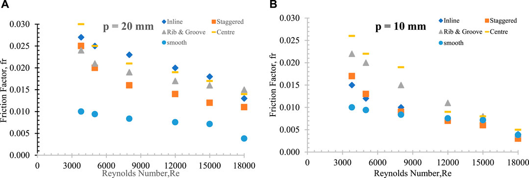
FIGURE 15. Variation in ƒ with varying Reynolds numbers for different positions of the rib at a relative pitch distance. (A) p = 20 mm and (B) p = 10 mm.
The pressure contour plots for relative pitch distances of p = 20 mm and p = 10 mm are illustrated in Figure 16 and Figure 17. These plots unveil that, at a higher Reynolds number Re = 18,000, there is a sudden increase in pressure near the entry region of the test section due to the presence of the rough surface. Notably, a significant impact is observed, with a larger circulation created at the smaller pitch distance of p = 10 mm compared to p = 20 mm in the case of ribs positioned in-line. A similar pattern is observed in the rib and groove configurations. In contrast, staggered rib positioning and center rib positioning result in the generation of substantial turbulence that is symmetrically directed toward the wall region. It is noteworthy that at a maximum Reynolds number Re = 15,000 and a pitch distance of p = 20 mm, a lower friction factor is obtained, whereas at Re = 18,000 and p = 10 mm, the ƒ is higher.
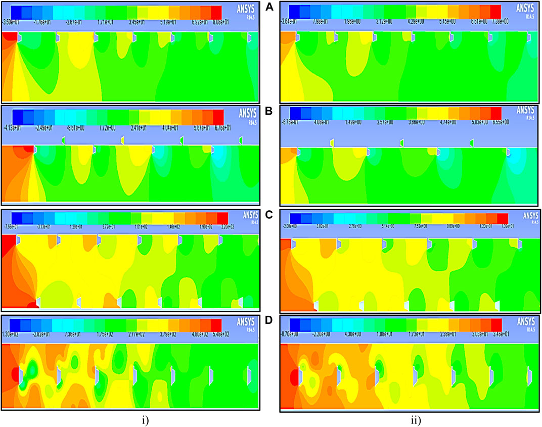
FIGURE 16. Contour plot of pressure at relative pitch distances p = 20 mm in the polygonal rib at a Reynolds number of (i) 18,000 and (ii) 3,800. (A) Inline, (B) staggered, (C) rib and groove, and (D) rib at the center.
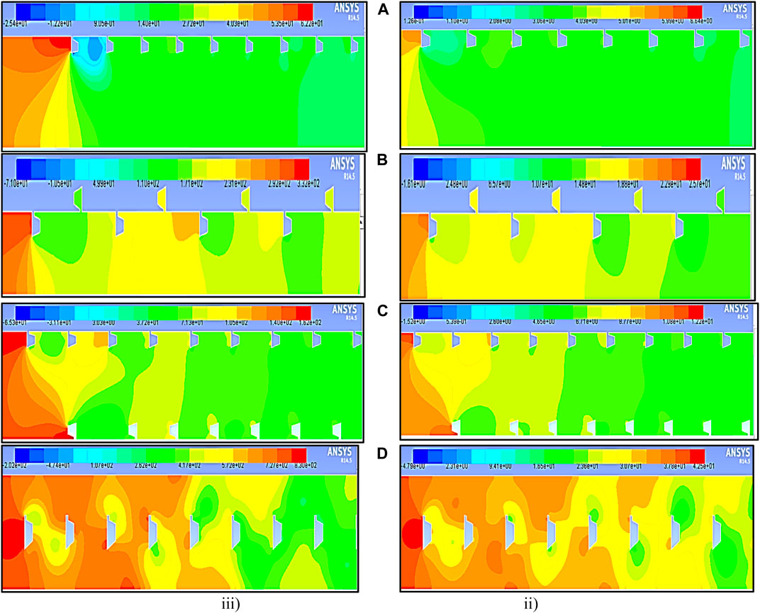
FIGURE 17. Contour plot of pressure at relative pitch distance p = 10 mm in the polygonal rib at a Reynolds number of (i) 18,000 and (ii) 3,800. (A) Inline, (B) staggered, (C) rib and groove, and (D) rib at the center.
The aim of the present research work is to investigate the impact of the position of polygonal-shaped ribs with different relative pitch distances on heat transfer and friction in an SAH (Webb and Eckert, 1972). Eq. 8 is used to evaluate the thermal and hydraulic performance of the SAH, and the resulting average Nu and friction factor values are presented in Figure 18 for relative pitch distances of p = 20 mm and p = 10 mm. The analysis illustrates that the thermo-hydraulic performance parameter (THPP) values range from 0.43 to 2.81 for all proposed rib shapes, as presented in Table 5. It is noted that decreasing the relative pitch distances of the ribs leads to an increase in the average Nu due to boundary layer interruption, while increasing the pitch distances leads to a decrease in the average ƒ. The staggered polygonal-shaped rib with a relative pitch distance of p = 10 mm at Reynolds number 8000 achieved the highest THP value of 2.81. Table 6 provides a comparative evaluation of rough surface shapes that have been previously published, alongside their associated THP values. This comparison showcases a noteworthy improvement associated with the projected rib, as validated by the thermal enhancement factor. The table further illustrates the diverse configurations of polygonal-shaped ribs, each characterized by varying relative pitch distance.
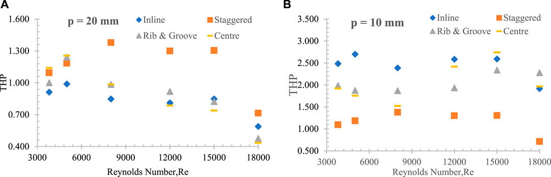
FIGURE 18. Comparison of thermo-hydraulic performance of various rib positions at (A) p = 20 mm and (B) p = 10 mm with Reynolds number.

TABLE 5. Thermo-hydraulic performance parameter.
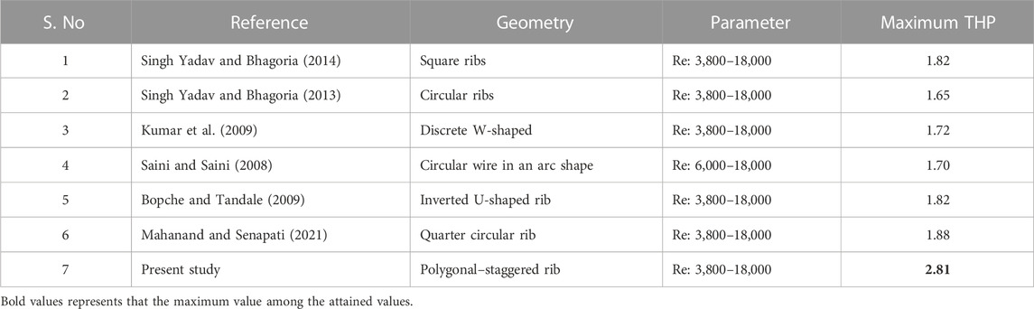
TABLE 6. THP values compared with earlier published work (Varun Kumar et al., 2021).
It assesses heat transfer improvement through thermal performance and evaluates the additional frictional resistance through hydraulic performance (Webb and Eckert, 1972). Eq. 8 is used to predict the THP of the SAH, and the resulting average Nu and ƒ values are plotted in Figure 18 for pitch distances of p = 20 mm and p = 10 mm. By analyzing the present proposed shapes with varying relative pitch distances, it was observed that the THPP value varied between 0.43 and 2.81, as shown in Table 5. This variation in THPP helps identify the effectiveness of the proposed ribs in enhancing the THP of the SAH. The observation indicates that reducing the pitch distances between the ribs significantly disrupts the boundary layer, leading to an increase in the average Nu.
Conversely, increasing pitch distances results in a decrease in the average friction factor. Notably, the staggered polygonal rib shape with a relative pitch distance of p = 10 mm at an Re of 8000 achieved a maximum THP of 2.81. The THP values obtained were compared with those of previously published rib shapes and their respective THP outcomes, as outlined in Table 6. This comparison underscores a significant enhancement in the proposed rib configuration, a conclusion further validated by the thermal enhancement factor.
The study analyzed the numerical results of a 2D rectangular duct in an SAH with artificial rough surfaces of polygonal-shaped ribs placed at various positions inside the duct. The study investigated the impact of relative roughness pitch distances on the average Nu, ƒ, and THP parameters. The following conclusions were made
1. The study’s analysis unequivocally validates that the incorporation of artificial roughness in a rectangular duct significantly elevates the heat transfer coefficient compared to a smooth surface.
2. Diverse turbulent models were assessed, and it was found that the RNG k-ϵ model consistently produces results closely aligned with the empirical values of the Dittus–Boelter equation, bolstering confidence in its applicability.
3. The investigation identifies that the most effective heat transfer enhancement is achieved by using polygonal-shaped ribs positioned at the center of the duct with a relative pitch distance of p = 10 mm, particularly in cases of lower Reynolds numbers (Re 3800). This configuration attains a maximum average Nusselt number of 3.76, surpassing the 3.42 Nusselt number recorded at p = 20 mm and Re 3,800.
4. Notably, the study reveals a substantial increase in the friction factor (ƒ) with the introduction of artificial roughness. At a relative pitch distance of p = 20 mm and Reynolds number of 18000, the maximum ƒ is 3.66 times that of a smooth surface, and at p = 10 mm, it is 2.6 times higher.
5. In the context of staggered rib positioning at a relative pitch distance of p = 10 mm and Reynolds number Re 8000, the research identifies the attainment of the highest peak THP, which reaches 2.813.
The raw data supporting the conclusion of this article will be made available by the authors, without undue reservation.
BK: conceptualization, data curation, formal analysis, investigation, validation, and writing–original draft. CS: data curation, investigation, software, and writing–original draft. PK: conceptualization, formal analysis, methodology, writing–original draft, and writing–review and editing. DT: data curation, formal analysis, supervision, and writing–review and editing. MS: data curation, validation, and writing–review and editing. JT: conceptualization, supervision, validation, and writing–review and editing.
The author(s) declare that no financial support was received for the research, authorship, and/or publication of this article.
The authors declare that the research was conducted in the absence of any commercial or financial relationships that could be construed as a potential conflict of interest.
All claims expressed in this article are solely those of the authors and do not necessarily represent those of their affiliated organizations, or those of the publisher, the editors, and the reviewers. Any product that may be evaluated in this article, or claim that may be made by its manufacturer, is not guaranteed or endorsed by the publisher.
Alam, T., and Kim, M.-H. (2016). Numerical study on thermal hydraulic performance improvement in solar air heater duct with semi ellipse shaped obstacles. Energy, V. 112, 588–598. doi:10.1016/j.energy.2016.06.105
Alam, T., and Kim, M.-H. (2017). Heat transfer enhancement in solar air heater duct with conical protrusion roughness ribs. Appl. Therm. Eng. 126, 458–469. doi:10.1016/j.applthermaleng.2017.07.181
Arya, N., Goel, V., and Sunden, B. (2023). Solar air heater performance enhancement with differently shaped miniature combined with dimple shaped roughness: CFD and experimental analysis. Sol. Energy 250, 33–50. doi:10.1016/j.solener.2022.12.024
ASHRAE (2003). Method of testing to determine the thermal performance of solar collectors. Atlanta, GA: American Society of Heating, Refrigeration and Air Conditioning Engineers, 42.
Bopche, S. B., and Tandale, M. S. (2009). Experimental investigations on heat transfer and frictional characteristics of a turbulator roughened solar air heater duct. Int. Commun. Heat Mass Transf. 52, 2834–2848. doi:10.1016/j.ijheatmasstransfer.2008.09.039
Eiamsa-ard, S., and Promvonge, P. (2008). Numerical study on heat transfer of turbulent channel flow over periodic grooves. Int. Commun. Heat. Mass Transf. 35, 844–852. doi:10.1016/j.icheatmasstransfer.2008.03.008
Eiamsa-ard, S., and Promvonge, P. (2009). Thermal characteristics of turbulent rib-grooved channel flows. Int. Commun. Heat. Mass Transf. 36, 705–711. doi:10.1016/j.icheatmasstransfer.2009.03.025
Gawande, V. B., Dhoble, A. S., Zodpe, D. B., and Chamoli, S. (2016). Experimental and CFD investigation of convection heat transfer in solar air heater with reverse L-shaped ribs. Sol. Energy 131, 275–295. doi:10.1016/j.solener.2016.02.040
Kumar, A., Bhagoria, J. L., and Sarviya, R. M. (2009). Heat transfer and friction correlations for artificially roughened solar air heater duct with discrete W-shaped ribs. Energy Conversat. Manag. 50, 2106–2117. doi:10.1016/j.enconman.2009.01.025
Kumar, S., Das, R. K., Kulkarni, K., Alam, T., and Eldin, S. M. (2023). Designing of low-cost solar air heater equipped with roughness of streamlined cross-section. Case Stud. Therm. Eng. 45, 102915, 102915. doi:10.1016/j.csite.2023.102915
Mahanand, Y., and Ranjan Senapati, J. (2020). Thermal enhancement study of a transverse inverted-T shaped ribbed solar air heater. Int. Commun. Heat Mass Transf. 119, 104922. doi:10.1016/j.icheatmasstransfer.2020.104922
Mahanand, Y., and Senapati, J. R. (2021). Thermo-hydraulic performance analysis of a solar air heater (SAH) with quarter-circular ribs on the absorber plate: a comparative study. Int. J. Therm. Sci. 161, 106747. doi:10.1016/j.ijthermalsci.2020.106747
Maithani, R., Kumar, A., Ali, M. A., Gupta, N. K., Sharma, S., Alam, T., et al. (2023). Exergy and sustainability analysis of a solar heat collector with wavy delta winglets as turbulent promoters: a numerical analysis. Case Stud. Therm. Eng. 49, 103293. doi:10.1016/j.csite.2023.103293
Pandey, N. K., Bajpai, V. K., and Varun, (2016). Experimental investigation of heat transfer augmentation using multiple arcs with gap on absorber plate of solar air heater. Sol. Energy 134, 314–326. doi:10.1016/j.solener.2016.05.007
Promvonge, P., Skullong, S., Kwankaomeng, S., and Thiangpong, C. (2012). Heat transfer in square duct fitted diagonally with angle-finned tape–Part 1: experimental study. Int. Commun. Heat. Mass Transf. 39 (5), 617–624. doi:10.1016/j.icheatmasstransfer.2012.03.007
Promvonge, P., and Thianpong, C. (2008). Thermal performance assessment of turbulent channel flows over different shaped ribs. Int. Commun. Heat. Mass Transf. 35, 1327–1334. doi:10.1016/j.icheatmasstransfer.2008.07.016
Saini, R. P., and Saini, S. K. (2008). Development of correlations for Nusselt number and friction factor for solar air heater with roughened duct having arc-shaped wire as artificial roughness. Sol. Energy 82, 1118–1130. doi:10.1016/j.solener.2008.05.010
Saini, R. P., and Verma, J. (2008). Heat transfer and friction factor correlations for a duct having dimple shape artificial roughness for solar air heaters. Energy 33, 1277–1287. doi:10.1016/j.energy.2008.02.017
Singh, J., Singh Bisht, V., Bhandari, P., Kumar, K., Singh, J., Alam, T., et al. (2023). Computational parametric investigation of solar air heater with dimple roughness in S-shaped pattern. Int. J. Interact. Des. Manuf. (IJIDeM. doi:10.1007/s12008-023-01392-8
Singh Yadav, A., Agrawal, A., Sharma, A., and Gupta, A. (2022b). Revisiting the effect of ribs on performance of solar air heater using CFD approach. Mater. today Proc. 63, 240–252. doi:10.1016/j.matpr.2022.02.549
Singh Yadav, A., Alam, T., Gupta, G., Saxena, R., Gupta, N. K., Viswanath Allamraj, K., et al. (2022a). A numerical investigation of an artificially roughened solar air heater. Energies 15 (21), 8045. doi:10.3390/en15218045
Singh Yadav, A., and Bhagoria, J. L. (2013). A CFD (computational fluid dynamics) based heat transfer and fluid flow analysis of a solar air heater provided with circular transverse wire rib roughness on the absorber plate. Energy 55, 1127–1142. doi:10.1016/j.energy.2013.03.066
Singh Yadav, A., and Bhagoria, J. L. (2014). A numerical investigation of square-sectioned transverse rib roughened solar air heater. Int. J. Therm. Sci. 79, 111–131. doi:10.1016/j.ijthermalsci.2014.01.008
Sripattanapipat, S., and Promvonge, P. (2009). Numerical analysis of laminar heat transfer in a channel with diamond-shaped baffles. Int. Commun. Heat. Mass Transf. 36, 32–38. doi:10.1016/j.icheatmasstransfer.2008.09.008
Taler, D., and Jan, T. (2017). Simple heat transfer correlations for turbulent tube flow. E3S Web Conf. 13, 02008. doi:10.1051/e3sconf/20171302008
Varshney, L., and Gupta, A. D. (2017). Performance prediction for solar air heater having rectangular sectioned tapered rib roughness using CFD. Therm. Sci. Eng. Prog. 4, 122–132. doi:10.1016/j.tsep.2017.09.005
Varun Kumar., B., Manikandan, G., Rajesh Kanna, P., Taler, D., Taler, J., Nowak-Ocłoń, M., et al. (2018). A performance evaluation of a solar air heater using different shaped ribs mounted on the absorber plate—a review. Energies 11, 3104. doi:10.3390/en11113104
Varun Kumar, B, Manikandan, G, and Rajesh Kanna, G. P. (2021). Enhancement of heat transfer in SAH with polygonal and trapezoidal shape of the rib using CFD. Energy, V. 234, 121154. doi:10.1016/j.energy.2021.121154
Verma, S., and Prasad, B. (2000). Investigation for the optimal thermohydraulic performance of artificially roughened solar air heaters. Renew. Energy 20, 19–36. doi:10.1016/S0960-1481(99)00081-6
Webb, R. L., and Eckert, E. R. G. (1972). Application of rough surfaces to heat exchanger design. Int. J. Heat. Mass Transf. 15 (9), 1647–1658. doi:10.1016/0017-9310(72)90095-6
Keywords: rough surface, polygonal rib with groove, THP, solar air heater, Nusselt number, numerical simulation
Citation: Kumar BV, Selvan CP, Kanna PR, Taler D, Szymkiewicz M and Taler J (2023) Numerical investigation of heat transfer enhancement in solar air heaters using polygonal-shaped ribs and grooves. Front. Energy Res. 11:1279225. doi: 10.3389/fenrg.2023.1279225
Received: 17 August 2023; Accepted: 30 October 2023;
Published: 28 November 2023.
Edited by:
Mahendran Samykano, Universiti Malaysia Pahang, MalaysiaReviewed by:
Tabish Alam, Central Building Research Institute (CSIR), IndiaCopyright © 2023 Kumar, Selvan, Kanna, Taler, Szymkiewicz and Taler. This is an open-access article distributed under the terms of the Creative Commons Attribution License (CC BY). The use, distribution or reproduction in other forums is permitted, provided the original author(s) and the copyright owner(s) are credited and that the original publication in this journal is cited, in accordance with accepted academic practice. No use, distribution or reproduction is permitted which does not comply with these terms.
*Correspondence: Jan Taler, amFuLnRhbGVyQHBrLmVkdS5wbA==; P. Rajesh Kanna, cHJrYW5uYUBnbWFpbC5jb20=
Disclaimer: All claims expressed in this article are solely those of the authors and do not necessarily represent those of their affiliated organizations, or those of the publisher, the editors and the reviewers. Any product that may be evaluated in this article or claim that may be made by its manufacturer is not guaranteed or endorsed by the publisher.
Research integrity at Frontiers
Learn more about the work of our research integrity team to safeguard the quality of each article we publish.