 Muhammad Ijaz1
 Jameel Ahmad
 Khursheed Aurangzeb
 Faisal Saleem
94% of researchers rate our articles as excellent or good
Learn more about the work of our research integrity team to safeguard the quality of each article we publish.
Find out more
ORIGINAL RESEARCH article
Front. Energy Res., 15 September 2023
Sec. Process and Energy Systems Engineering
Volume 11 - 2023 | https://doi.org/10.3389/fenrg.2023.1272329
Introduction: The proportional resonant (PR) controller is known for its ability to effectively regulate sinusoidal current and voltage with low steady-state error. However, in the context of digital power systems, where operations are discrete in time, applying conventional PR controllers directly presents challenges. This study investigates the impact of various discretization methods on the performance of PR controllers, particularly under scenarios with varying reference frequencies.
Methods: To assess the performance of digital PR controllers under varying reference frequency conditions, three discretization techniques are employed: zero-order hold (ZOH), impulse invariant (II), and zero pole matching (ZPM), in addition to the conventional deadbeat controller. These controllers are tested in conjunction with a single-phase pulse-width modulated (PWM) inverter, which is a crucial component in modern power systems.
Results: Simulation results indicate the effectiveness of the different digital PR controllers in tracking both fixed and variable reference frequency signals while minimizing total harmonic distortion (THD) and steady-state error. When utilizing only the deadbeat controller, steady-state error and THD are measured at 4.9 V and 4.82%, respectively. However, the proposed ZPM-based digital PR controller significantly improves performance, reducing steady-state error to 0.12 V and THD to 0.45%, highlighting its superior performance.
Discussion: The findings of this study emphasize the importance of choosing the appropriate discretization method when implementing PR controllers in digital power systems. The ZPM-based digital PR controller proves to be highly efficient in regulating power converters under varying grid frequency conditions. This research contributes to the understanding of digital PR controller behavior and its potential for improving power system performance, especially in scenarios with intermittent renewable energy resources and fluctuating grid frequencies.
In electrical power systems, the grid frequency typically remains relatively stable, but in systems like microgrids, isolated grids, or grids with high penetration of renewable energy sources, the frequency might deviate from the standard value. This can result from variations in generation, load, or the presence of intermittent renewable sources such as solar and wind. The concept of digital resonant control involves designing control algorithms that can detect and mitigate resonant conditions within the system. Resonance occurs when the natural frequency of the power converter circuit matches the frequency of the grid fluctuations. This can lead to amplified voltage or current oscillations, potentially causing instability, voltage distortion, and even damage to the converter and connected components. The control system continuously monitors the grid frequency, which might be non-constant due to variable generation and load conditions.
The control algorithm analyzes the system’s response to the varying grid frequency to detect any signs of resonance. This involves monitoring the voltage and current waveforms and identifying harmonic components that might indicate resonance. Once resonance is detected, the control algorithm adjusts the converter’s control parameters in real-time to counteract the effects of resonance. This might involve tuning the converter’s output impedance or adjusting the control loop gains. The control strategy can incorporate damping techniques and filtering to reduce the impact of resonance on the system. This could include adding virtual resistors or filters to dampen oscillations and prevent them from increasing.
In addition to resonance control, the algorithm might include synchronization techniques to ensure that the converter output is synchronized with the variable grid frequency, maintaining stable operation and minimizing voltage and current distortions. Digital resonant control is particularly valuable in scenarios where traditional control methods might struggle to maintain stability under varying grid frequency conditions. Its adaptive nature allows power converters to respond in real-time to changes in the system dynamics, thereby improving overall system performance, efficiency, and reliability. This control strategy is crucial for the successful integration of renewable energy sources into the grid, as these sources often introduce variability in the grid frequency. Digital resonant control enhances the stability and robustness of power electronic systems by effectively managing resonant conditions, ensuring smooth operation even in challenging grid conditions.
Renewable energy has the ability to cope with ever-increasing energy needs. It supplies electric power directly to the consumer or connects to the main grid. Solar photovoltaic (PV) and wind energy-based power systems Dong et al. (2023); Desalegn et al. (2023); Khan et al. (2022) are inherently stochastic in nature due to changing weather conditions such as irradiance and temperature variations in the case of the solar PV system and wind speed variations in the case of the wind energy conversion system. PV systems and wind integrated systems directly supply energy to the consumers such as residential, commercial, or industrial loads or connect to the main grid using DC–DC or DC–AC converters. There are many associated challenges such as grid stability and bi-directional power flow control in hybrid energy systems (HESs) in electric vehicles that use multi-port bi-directional converters (Malik et al., 2023a; Malik et al., 2023b). With variable weather conditions, the PV system suffers low voltage at the output; in this scenario, the DC–DC boost converter becomes a very necessary part to get high voltage gain Malik et al. (2017). The frequency of the output voltages must also be tightly regulated before injecting the output power into the grid Yasmeena and Das (2015)-Chen et al. (2021) from these renewable systems.
Recently, concentrated photovoltaic (CPV) has been given preference over conventional photovoltaic due to its high efficiency. The solar cell area can be augmented with optical concentrators Iqbal et al. (2023), thereby improving efficiency of renewable solar-powered systems. Short-term load forecasting technologies can also be integrated with modern photovoltaic-based energy conversion system to further improve in the planning of energy demand, smart and efficient economic dispatch, and energy management of electrical power Javed et al. (2021)-Wei et al. (2023). However, without efficient grid synchronization Lin et al. (2023, 2022) and load frequency control (LFC), it degrades power quality and increases total harmonic distortion (THD) in the power network Ahsan et al. (2021); Liu et al. (2023) or drive systems coupled with it Liu and Liu (2021). To solve this problem, various classical control system approaches, such as proportional integral (PI) controller, deadbeat controllers, hysteresis controllers, repetitive controllers, and current controllers based on resonant filters, are employed with certain limitations such as hardware complexity and non-zero steady-state error performance Bourguiba et al. (2016) - Nazir et al. (2020).
A proportional resonant controller (PRC) is a control technique that combines the principles of proportional control with the ability to address resonant frequencies in a system. PRCs have garnered significant attention due to their effectiveness in dealing with resonance-related issues in various applications. This literature review provides an overview of key research findings, advancements, and applications related to PRCs. PRCs combine the features of proportional control with the capability to address resonant frequencies, making them well-suited for applications requiring precise control in the presence of resonant phenomena. Resonant controllers can be used to manage harmonic distortion in power electronics systems, demonstrating their ability to selectively attenuate specific frequency components in control signals while maintaining proportional control action. PRCs can be applied to grid-connected converters and voltage source inverters, aiming to enhance the power quality by suppressing current harmonics and damping resonances, thereby improving the dynamic response and stability of renewable energy systems.
In the realm of motor drives and motion control, PRCs have demonstrated their potential to mitigate mechanical resonances. Advancements in PRCs have focused on refining control strategies and tuning methodologies. Adaptive tuning techniques have been explored to optimize PRC parameters in real-time, adapting to changes in system dynamics and load conditions. Moreover, the integration of PRCs with advanced control algorithms, such as predictive control and sliding mode control, has been investigated to achieve higher accuracy and robustness.
The prevalence of digital control systems has led to extensive research on the digital implementation of PRCs. Zero-order hold and bilinear transformation techniques have been employed to adapt continuous-time PRC designs for digital platforms. Recent research has expanded the concept of PRCs to hybrid and multi-resonant control strategies. Researchers have integrated PRCs with other control techniques, such as repetitive control, to address multiple resonant frequencies in complex systems. These hybrid approaches aim to enhance control performance by effectively managing multiple resonance-related challenges.
The PRC is one of the most promising approaches that has recently gained considerable attention in regulating sinusoidal current and voltage signals in the case of grid-tied inverters Kuperman (2015). The PR controller is based on the internal model principle (IMP), which has the capability of providing a high-quality sinusoidal signal in the case of grid-connected inverters Quan and Cai (2010). In fact, the PR controller is the real alternative to conventional PI controllers that operate in positive and negative synchronous frame sequences Wang et al. (2018); Tarraso et al. (2017). Only the integration of the PR controller and PI controllers is different. The PR controller integrates at resonant frequency without producing phase shift and steady-state error.
In the synchronous frame of reference, PR controller performance and transient response are almost similar to those of traditional PI controller D. Zammit and Apap (2014). However, the performance of the PR controller is much better when controlling sinusoidal signals. The PR controller overcomes the shortcomings of the PI controller, such as the poor and sluggish tracking of sinusoidal reference signals and disturbance rejection Lakshmi and Naik (2017). Other advantages of the PR controller over the conventional PI controller are lower complexity and computational burden, direct connection to single-phase PWM inverters, and lower sensitivity Essaghir et al. (2018).
PR controller applications are widely applied to photovoltaic inverters, wind turbines, power converters, and uninterrupted power supplies Buso and Mattavelli (2015)- Husev et al. (2020). The PR controller is tuned to the fundamental frequency of the system to ideally provide infinite gain at the resonant frequency and almost no attenuation outside this frequency. Therefore, the PR controller can also be combined with a notch filter to compensate harmonics and to achieve good transient and steady-state objectives Rufa’I et al. (2019). Parvez et al. (2020) used the PR controller in the main control loop of an uninterrupted power supply inverter for low steady-state error, improved dynamic response, better output regulation, and lower THD. The dual integration method is commonly used to implement the PR controller due to the ease of frequency adaptation Das and Barai (2021).
In Mohammed et al. (2017), various control strategies are explored for integrating and managing renewable power injection into the grid. These strategies significantly contribute to enhancing power system stability, improving power quality, and overall system performance. Achievements include maintaining low total harmonic distortion (THD), achieving high-power factor, and demonstrating rapid dynamic responses. Additionally, the utilization of an algorithm for tracking the maximum power point (MPPT) in grid-connected photovoltaic inverters, along with the creation of a precise phase-locked loop (PLL) for phase angle detection, amplitude regulation, and voltage frequency control, plays a crucial role in ensuring accurate generation of reference signals.
The work presented by Li et al. (2021) introduces a sophisticated quasi-proportional integral resonant (QPIR) controller tailored for a three-phase LCL grid-connected inverter with integrated active damping. In contrast to conventional QPR controllers, this enhanced QPIR controller exhibits remarkable precision in its regulation of grid-connected voltages and currents. The innovative QPIR controller effectively attains autonomous control over both active and reactive power in the context of a three-phase grid-connected inverter. Notably, this controller excels in ensuring the simultaneous accuracy and swiftness of control over grid-connected currents, rendering it particularly pertinent for applications emphasizing high-power factors and aiming to optimize DC-side utilization efficiency. It is important to note, however, that while this controller demonstrates considerable promise, there are limitations preventing its direct applicability to practical systems.
In Alathamneh et al. (2022), the focus is on enhancing the stability of a grid-connected inverter operating under weak grid conditions. The study reveals that problematic negative resistance areas arise due to interactions between the phase-locked loop (PLL) and the grid voltage feedforward (GVF) elements. To counter this instability originating from the PLL and GVF, the research introduces a customized stability control method for grid-connected inverters. This approach revolves around modifying the impedance in the q-axis. Specifically, the proposed method integrates q-axis voltage directly into the q-axis current regulator’s output through a transfer link. This deliberate step effectively counteracts the adverse effects of both the PLL and GVF on the q-axis output impedance of the grid-connected inverter. However, it is important to note that this analysis is confined to a single inverter system.
In Gopinath and Vijayakumar (2022), a multi-level inverter designed for grid-connected converters is presented. This inverter tackles issues such as leakage current reduction, voltage enhancement, self-voltage balancing, and minimizing capacitor voltage stress. The suggested design proves to be a strong candidate for applications involving grid-connected photovoltaic systems.
Most of the prior research has focused on continuous-time design of the PR controller to achieve the desired performance, but these controllers cannot be applied directly to digital systems. Therefore, for the digital system, it is necessary to implement the PR controller digitally. Different discretization methods such as zero-order hold (ZOH), first-order hold (FOH), impulse invariant (II), and the zero pole matching (ZPM) method are used for digital implementation of the PR controller Yepes (2011). However, discretization of PR is not an easy task, as it causes displacement of poles and zeros of the controller. The displacement of zeros poses problems of stability, whereas the displacement of poles causes a resonant frequency shift, leading to steady-state error. Since sinusoidal voltage is the basic electrical variable of the power system, the main goal of this work is to propose an efficient discretization method used for digital implementation of the PR controller that can effectively track the frequency of the desired signal with zero steady-state error.
The remainder of the paper is organized as follows. Section 4 presents modeling of the single-phase PWM inverter. Section 5 presents the digital control techniques for the single-phase PWM inverter. Section 6 discusses in detail the discretization methods used for digital implementation of the PR controller and its effects on poles and zeros of the controller. It also provides three efficient discretization methods that can be used for PR controllers. Simulation results and discussion are given in Section 7. Section 8 concludes the paper.
A single-phase PWM inverter with the control loop is shown in Figure 1. It consists of DC input source, inverter bridge, low-pass LC filter, non-linear rectifier load, and PWM pulse generator. En represents the nominal value of the DC input source. The inverter bridge consists of four insulated gate bipolar transistor (IGBT) switches from S1 to S4 with protection diodes. The switches generate an alternating signal at the output, while the purpose of protection diodes is to provide a reverse path for current flow. The low-pass filter consists of an inductor Ln and a capacitor Cn, and the values of Ln and Cn are set to achieve the desired frequency response. The inverter may be standalone or grid-connected. In the standalone case, the generated AC power is supplied directly to consumers, while in the case of the grid-connected inverter, the AC output is delivered to the grid. The switching pattern of the inverter is decided by the PWM pulse generator. The PWM pulse generator is controlled by the controller circuit of the inverter. The desired voltage with nominal frequency is generated by efficiently controlling the PWM pulses to the input of the inverter Nazir et al. (2019).State space equations of the PWM inverter are given by Cha et al. (2015).
where En, vc, Cn, Ln, and Rn represent the inverter input voltage, pulse width modulated output voltage, nominal values of inductor, capacitor, and load resistor, respectively. The state space equation
Therefore, the discrete time version of Eq. 1 is given by Phillips et al. (2015).
where g1 = EnT/2LnCn,
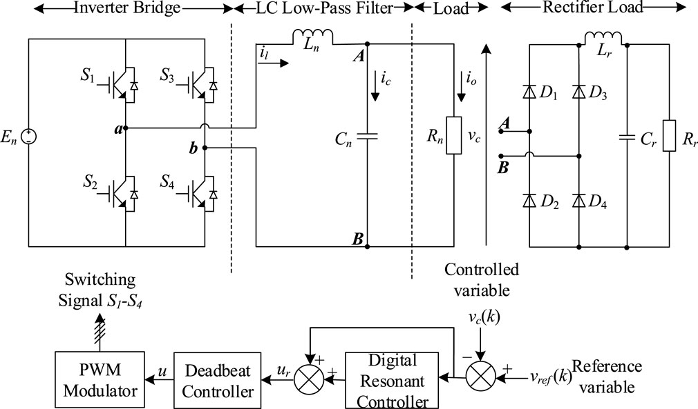
FIGURE 1. Schematic of the single-phase PWM inverter with control loop.
The PWM generator block, which is the built-in block of Simulink/MATLAB, is used to generate PWM pulses. The triangular carrier signal of the specified carrier frequency is compared with the sinusoidal modulating signal. The modulating signal is shown in Figure 2A. When the modulating signal is greater than the carrier pulse, 1 is high and 0 is low, otherwise. The PWM pulse for the other switch in the same leg is exactly the inverse of pulse 1, as can be seen in the first and second waveform of Figure 2B. For the switches of the second leg of the inverter, the PWM signals are generated by the comparison of the same triangular waveform with the negative of the modulating signal used for arm 1 (180 degrees phase shift).
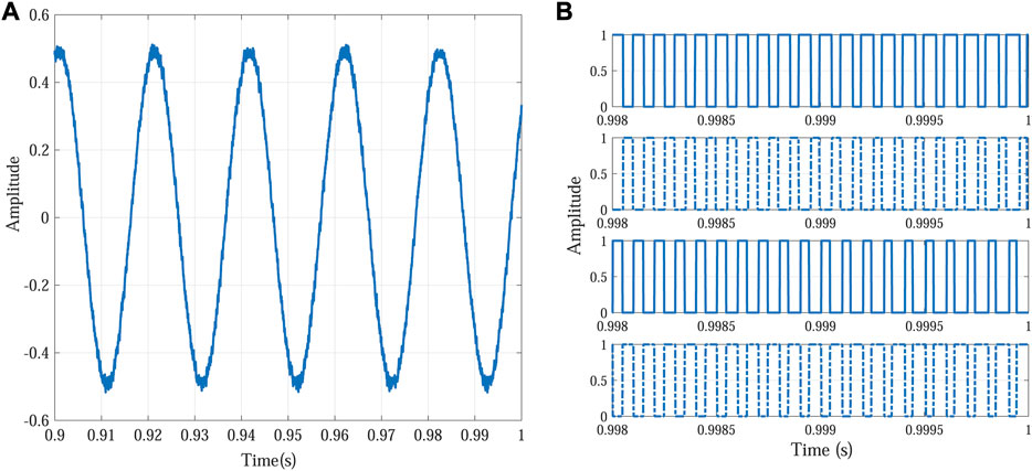
FIGURE 2. Pulse width-modulated control signal generation. (A) Modulating signal (B) and control pulses for transistors in the inverter.
The deadbeat controller is used as a feedback controller for an inverter to stabilize the plant. It is a digital controller and also has the ability to track the reference signal by generating suitable PWM pulses for switching of IGBTs. Among all digital controllers, the deadbeat controller has very fast transient response Iskhakov et al. (2013). Generally, the deadbeat controller is combined with other periodic digital controllers such as repetitive and resonant controllers to improve their transient response. Due to fast transient response, deadbeat control applications have been applied to power electronics since the 1980s Kukrer and Komurcugil (1999). The deadbeat control law is developed from the inverter plant Eq. 3. Suppose y(k) = vc(k) represents the output signal of the inverter and yref(k) the reference signal. So, the objective is to track the reference signal with zero steady-state error. After taking the z-transform of Eq. 3, the output y(k)becomes
and the difference equation is given by
where u(k) = ΔT(k)/T, a1 = −(Φ11 + Φ22), a2 = Φ11Φ22 − Φ12Φ21, b1 = g1T/E, and b2 = (g2Φ12 − g1Φ22)T/E.
Deadbeat or the one sample ahead preview equation is obtained by increasing the value of k in Eq. 5 by 1 and replace y (k + 1) by yref(k). Equation 6 describes the one sample ahead preview controller, and the deadbeat response with transfer function H(z) = z−1is achieved;
Thus, from Eq. 6, it is clear that the signal u(k) for generating the PWM pulse depends on the output signal at present and previous samples, the pulse signal of the previous sample, and the reference signal at the present sample. If all these coefficients ai and bi are calculated accurately, then the deadbeat controller is able to generate the output signal nearly equal to the reference signal. However, the deadbeat controller is more sensitive to measurement noise and parameter uncertainties, which may cause plant stability issues Wang et al. (2015).
Voltage and current distortions are the most critical issues in the case of the grid-tied inverter Choi et al. (2018). Therefore, an accurate control scheme is required for achieving low THD in output current and voltage. Inverters use the applications of the PR controller to generate a sinusoidal voltage and current waveforms with lower THD. Therefore, the PR controller can be adapted as an efficient current/voltage regulator for high-quality sinusoid of grid-tied inverter systems Silwal and Karimi-Ghartemani (2016). The block diagram of the controller in Figure 1 depicts a PR controller with a combination of the feedback controller for the single-phase PWM inverter. It yields an efficient signal u(k) to generate the PWM pulse for switching of IGBTs to provide the desired frequency output signal.
In this work, discrete time resonant controllers are applied to the inverter for achieving the desired results. The transfer function of the discrete time PR controller can be written as
The transfer function of the continuous time PR controller is given by
where Kp, Ki, and h represent proportional gain, integral gain, and harmonics order, respectively. The double integration-based controller, due to the ease of frequency adaptation, is used for implementation of the PR controller Das and Barai (2021). Figure 3 presents the dual integration-based implementation of the continuous time resonant controller, where the input hw1 represents the desired resonant frequency to be tracked Parvez et al. (2016). However, if various frequencies need to be tracked simultaneously, several resonant controllers can be implemented in parallel, and the transfer function of multiple resonant controllers is
where nh is the highest harmonic order and Kh is the integral gain at hth harmonic.
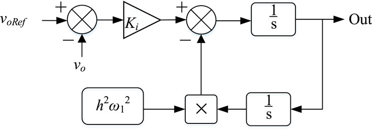
FIGURE 3. Block diagram of the double integration method-based PR controller.
The phase and magnitude response of a PR controller (314.16 rad/sec= 50 Hz) is presented in Figure 4. It can be observed that the PR controller ideally provides very high gain at the resonant frequency, i.e., 50 Hz only.
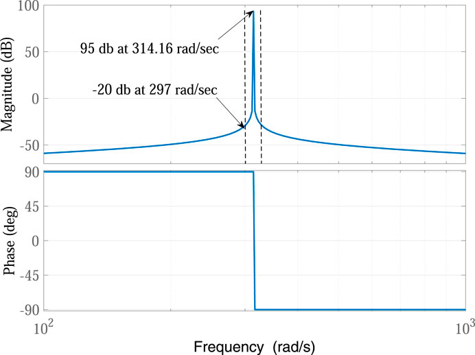
FIGURE 4. Bode plot of an ideal resonant controller, at w =314.16 rad/s and f = 50 Hz.
The transfer function of the PR controller, given by (9), can be discretized using various methods, such as ZOH, FOH, II, ZPM, forward Euler (FE), backward Euler (BE), Tustin (T), and Tustin with pre-warping (TP) Yepes et al. (2009). The PR controller is very sensitive to the discretization process due to its narrow band at resonance frequency Yepes et al. (2010). The two integrators in Figure 3, the forward and backward, are commonly discretized by using the Euler forward and backward discretization method Ghoshal and John (2017). Djordje in Stojic (2016) also suggested using modified Tustin or backward Euler simultaneously for discretization of both integrators. However, ZOH, FOH, II, and ZPM methods are simultaneously applied to both integrators. Table 1 shows different discretization methods and their corresponding transfer function used for digital implementation of the forward integrator. The integral part of the PR controller can be designated by Rh(s).
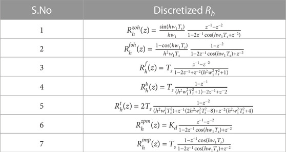
TABLE 1. Discretization of the integrator in the forward path Yepes et al. (2009).
As some of the discretization methods given in Table 1 have same denominators and only the numerators are different, therefore, based on the denominator, the transfer functions used for digital implementation of PR controllers can be classified into five groups given in Table 2 Yepes et al. (2011).
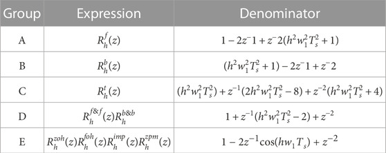
TABLE 2. Grouping of the digital resonant controller.
As the PR controller is very sensitive to the discretization process, it disturbs both poles and zero of the controller. Therefore, the effect of the discretization process must be considered and taken into account in application.
Figure 5 shows the pole plot of the digital controller transfer function presented in Table 2. Since group A and group B have no damping factor, which causes the poles of these groups cross the unit circle, therefore these groups should be avoided Phillips et al. (2015), where all other groups can move poles inside the unit circle because of the non-zero damping factor. Although groups C and D have infinite gain for the same value of hw1, but their poles are located at different position in z-plan, which may cause change in the location of the resonant frequency to be tracked. Enlarged portions of Figure 6 represent that C, D, and E groups result in different frequencies, and this difference is much higher for larger values of h. It can be seen in Figure 6 that 21st harmonic having frequency 1,050 Hz is better tracked by group E as compared to groups C and D, which results in an error of 36 Hz and 20 Hz, respectively. The error at the 5th harmonic was 0.4 Hz and 0.2 Hz for groups C and D, respectively. From Figure 5, it is clear that group E places poles of the controller inside the unit circle in z-plane. So, the digital controllers based on the group E discretization method are considered the best in terms of pole placement. However, it cannot be concluded at this point that which discretization technique among group E is the most efficient one in terms of zero mapping.
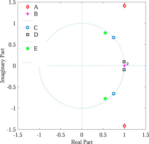
FIGURE 5. Pole plot of the digital resonant controller, at fs = 10 kHz.
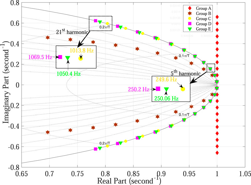
FIGURE 6. Pole plot of various groups of digital resonant controllers at fs = 10 kHz (odd harmonic components ranging from fundamental component to 21st harmonic). fs = 10 kHz.
The discretization process also has an effect on zeros of the controller and must not be ignored because it has a direct impact on the transient response and stability of the controller. However, if the transfer function of the controller is the Laplace transform of cosine function instead of sine function, then the effect on zero would be minimized and stability could be improved Chou and Liaw (2009). It has been observed in the previous section that group E discretization techniques mapped poles of the PR controller efficiently and provided infinite gain at resonance frequency. However, group E methods have different numerators and hence different zeros leading to different stability criteria. Therefore, it is required to point out the best discretization technique both in terms of accurate placement of poles and zeros of the controller.
Figure 7 depicts bode plot comparison of continuous time and group E-based discrete time PR controllers. It is clear from Figure 7 that among group E discretization techniques, the II method has the bode plot significantly different from the continuous time ideal PR controller at low frequencies; therefore, this method may not eliminate low-order harmonics effectively. Thus, the II discretization method must be avoided. The other two methods ZPM and ZOH perfectly follow the continuous time version of the PR controller; therefore, these methods result in superior performance in terms of stability and steady-state error. However, all three methods are capable of producing very high gain at the required frequency. In this case, the required frequency was non-integer (50.1 Hz), resulting in non-integer ratio between sampling and reference frequency, and all the considered digital PR controller effectively produced very high gain at the required frequency and low gain outside a nearly symmetric narrow band around that frequency.
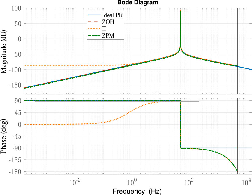
FIGURE 7. Frequency response of continuous time and group E-based digital PR controllers (f = 50.1 Hz).
It was clear previously that the poles and zero mapping efficiency of group E discretization (ZOH, II, and ZPM) methods were found satisfactory among the techniques given in the literature. Therefore, these three methods are used for digital implementation of the PR controller.
The transfer function of the digital PR controller based on the ZOH technique is given by Yepes et al. (2009)
The ZOH technique has both sine and cosine functions which may lead to complexity, and again there is a compromise between performance and complexity. Figure 8 depicts the ZOH-based discrete time resonant controller.
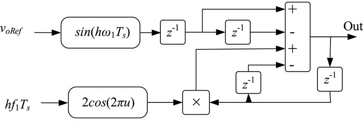
FIGURE 8. ZOH-based digital PR controller.
This technique is also used for discretization of the PR controller. It has good stability criteria and accurate pole placement qualities. In the double integration-based resonant controller, the impulse invariant method is applied separately to both integrators for discretization Silwal and Karimi-Ghartemani (2016). The transfer function of the discrete time resonant controller, by using the impulse invariant method, is given by Yepes et al. (2009)
where Ts is the sampling time, h harmonic order, and w1 is the desired resonant frequency at which we want, ideally, infinite gain. One drawback of this method is the presence of cosine functions in both the numerator and denominator, which causes computational burden, and hence need extra resources. So, there should be a compromise between the performance and complexity. Figure 9 shows the impulse invariant discretization method-based block diagram of the digital resonant controller.
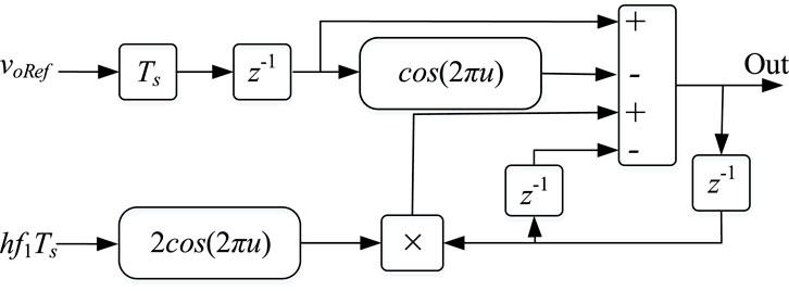
FIGURE 9. II-based digital PR controller.
The efficiency of the ZPM technique in terms of poles and zero mapping of the controller is much better than that of the other two methods discussed previously. This technique does not disturb the poles and zeros of the controller as when changing the transfer function from continuous time to discrete time. It has been observed previously that the frequency response of continuous time and discrete time PR controller is mostly similar. Therefore, there is a great motivation to use this method for discretizing the resonant controller. The transfer function of the digital PR controller based on the ZPM method is given by Yepes et al. (2009)
Figure 10 presents the schematic of the obtained digital PR controller.
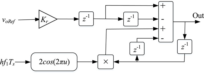
FIGURE 10. ZPM-based digital PR controller.
Figure 11 represents the overall block diagram of the single-phase PWM inverter including resonant and feedback controllers, where GRC(z), Gd(z), Gp(z), and d(z) represent the transfer function of the resonant controller, feedback controller, plant, and disturbance, respectively.
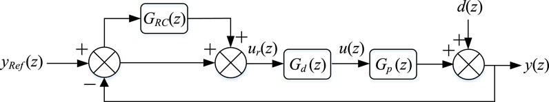
FIGURE 11. Control loop diagram of the PR controller with the deadbeat controller.
The system described by Figure 1 has been simulated using MATLAB SimulinkTM. The simulation parameters are given in Table 3. The variable frequency reference signal needs to be measured and provided to the controller in practical implementations. However, in this work, the variable frequency reference signal is directly generated and provided to the controller. Steady-state error and THD of output voltage for non-linear rectifier load are the parameters to be observed. The tracking capability of the conventional deadbeat controller alone and in combination with three types of digital PR controllers is examined in the presence of the variable frequency reference signal.
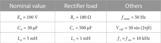
TABLE 3. Simulation parameters.
First of all, steady-state error and THD of the deadbeat controlled single-phase inverter are examined by continuously updating the delay element to the nearest integer value, and then these parameters are investigated for three types of digital PR controllers plugged into the deadbeat controlled inverter. Controllers are initially tuned at 50 Hz nominal frequency, while the frequency of the reference signal is varying between 49 Hz and 51 Hz with a step size of 0.1 Hz. It is observed from Figure 12 and Figure 13 that the deadbeat controller is unable to track the reference signal efficiently because the corresponding error and THD of output voltage are approximately 5 V and 5%, respectively. This is not acceptable for hardware implementation as practical implementation incurs much higher error than simulated work. Other three types of digital PR controllers track the reference signal with lesser THD and relatively small steady-state error. However, the performance of the ZPM-based digital PR controller is more satisfactory (nearly constant) among the three types of digital PR controllers.
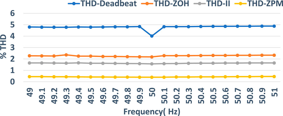
FIGURE 12. THD performance of the deadbeat controller compared with the ZOH-, II-, and ZPM-based PR controller.
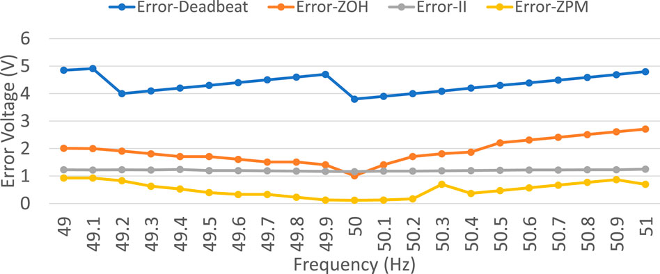
FIGURE 13. Error performance of the deadbeat controller compared with the ZOH-, II-, and ZPM-based PR controller.
The tracking efficiency of the controllers is checked for three selected frequencies of the reference signal.
Figure 14 describes the performance of a single-phase PWM inverter controlled by the deadbeat controller compared with other three types of digital PR controllers under a variable frequency. The result of the simulation shows that the ordinary digital PR controller fails to effectively track the reference signal because, at a certain reference signal frequency, the corresponding THD and the steady-state error of the output voltage are approximately equal to 5% and 5 V, respectively, which exceeds the limits of the international standard, although in simulation all things are taken into account ideally. Therefore, in practical systems, using only the deadbeat controller should be avoided for tracking/rejection of periodic signals. Three different frequencies of the reference signal, i.e., 49.7 Hz, 50 Hz, and 50.9 Hz, are considered to show the comparison of output and reference voltage signals, where 50 Hz is the frequency at which the controller is tuned and minimum THD was recorded among the observed results, while other two are the reference signal frequencies at which maximum THDs in output voltage were recorded. Figure 14 shows the tracking response of the deadbeat controller at three selected reference signal frequencies, where red signals represent the reference signal, while the green signals are the corresponding output signal. From the figures it is concluded that the output signal is more distorted at certain instants of time, which is due to the instability of the plant caused by the ordinary digital PR controller at that particular time. Therefore, more THDs and steady-state errors were recorded for the deadbeat controller.
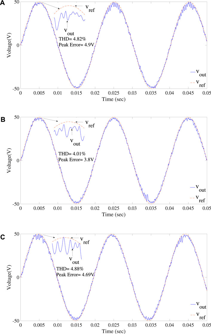
FIGURE 14. Response of the deadbeat controller at (A) fref = 49.7 Hz, (B) fref = 50Hz, and (C) fref = 50.9 Hz reference signal frequency.
Figure 15 illustrates the tracking performance of a ZOH-based digital PR controller for three selected frequencies of the reference signal. It also illustrates the tracking performance of a ZOH-based digital PR controller in terms of error and THD of the output voltage. It is clear from the figures (Figures 14–17) that even though the frequency of the reference signal varies, but the error and THD are almost constant, it means that the performance of the ZOH-based digital PR controller is lightly affected by the fluctuation of frequency. However, at some frequencies, the THD and error in the output is more than 2% and 2 V, respectively, which may limit the practical use of the ZOH-based digital PR controller, where low THD and zero steady-state error in output voltage are required. Figure 15 shows the response of the ZOH-based digital PR controller for three different frequencies of the reference signal, in order to highlight the comparison between the reference and output voltage signal. The selected frequencies include the frequency at which the controller is tuned, i.e., 50 Hz, and other two are the frequencies at which the highest THDs and steady-state error were recorded among the observed values. It is clear from the figures that the tracking capability of the ZOH-based digital PR controller is much better than that of an ordinary digital PR controller. The controller takes some time before starting to work properly. An abrupt change in the output signal nearly at t = 4 msec is due to the transient time of the controller.
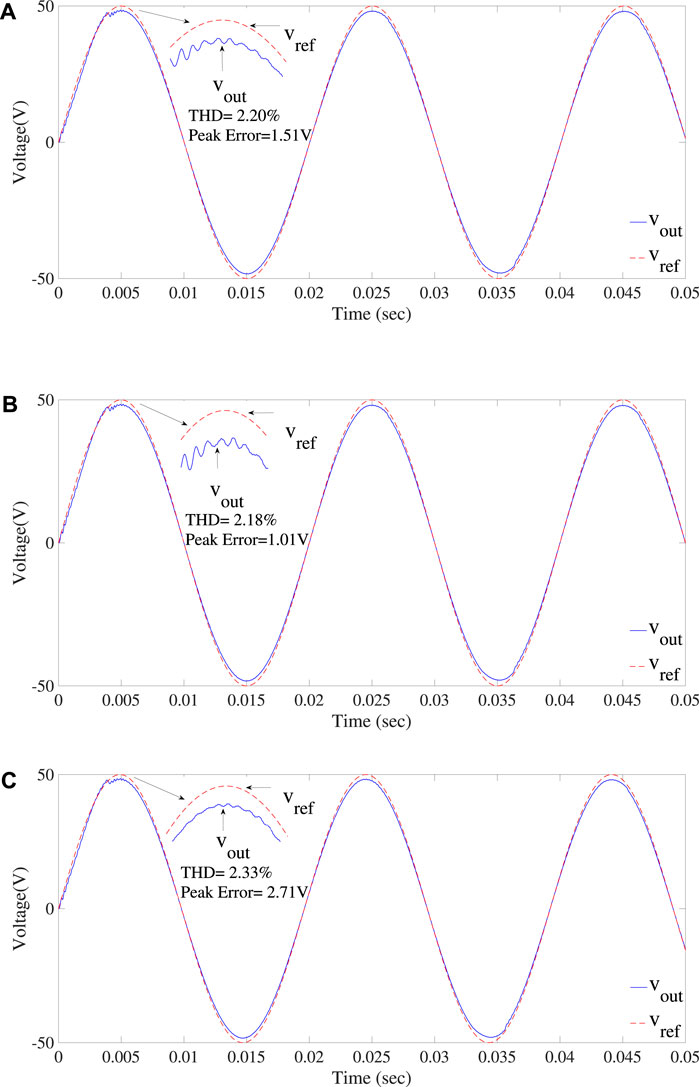
FIGURE 15. Response of the ZOH-based digital PR controller at (A) fref = 49.8 Hz, (B) fref = 50Hz, and (C) fref = 51Hz reference signal frequency.
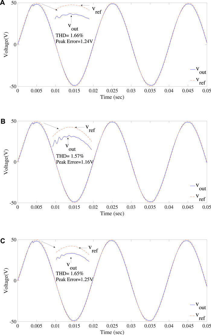
FIGURE 16. Response of the II-based digital PR controller at (A) fref = 49.4 Hz, (B) fref = 50Hz, and (C) fref = 51Hz reference signal frequency.
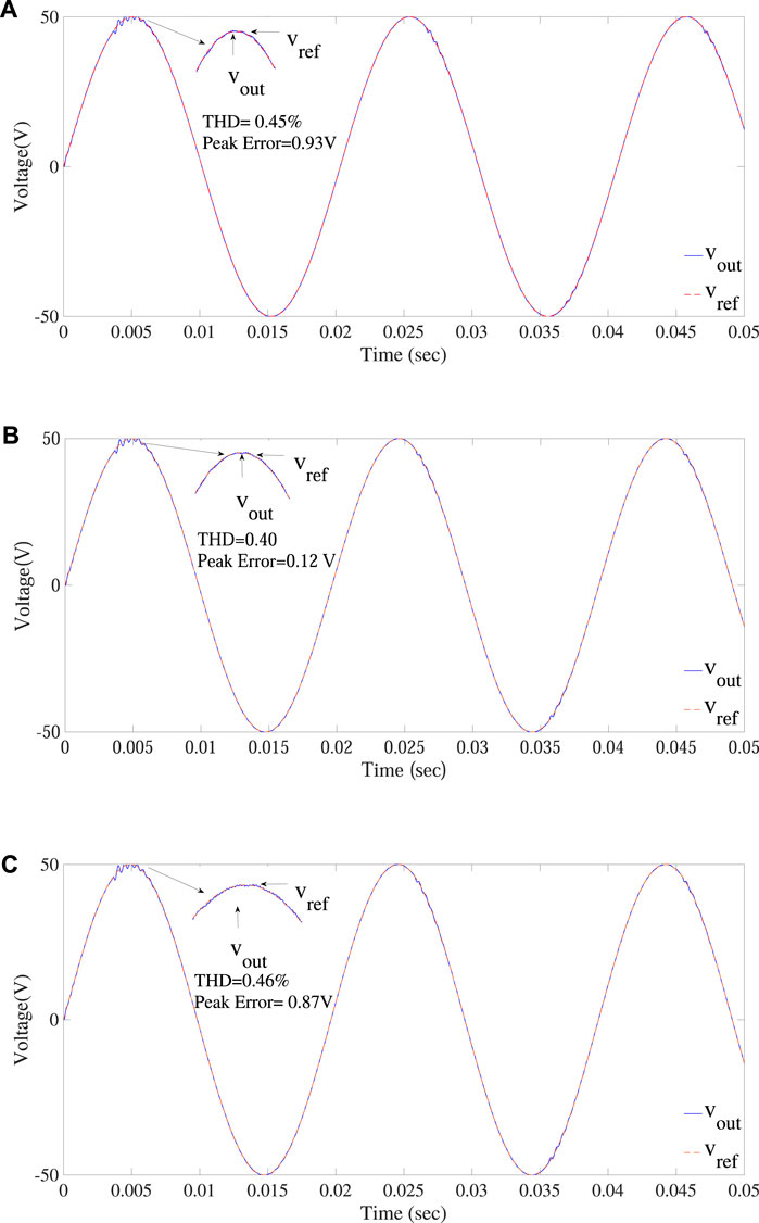
FIGURE 17. Response of the ZPM-based digital PR controller at (A) fref = 49Hz, (B) fref = 50Hz, and (C) fref = 50.9 Hz reference signal frequency.
One of the investigated efficient digital PR controllers is based on the II discretization method. The performance of the II discretization-based controlled inverter under varying frequency is summarized in Figure 12 and Figure 13. The frequency of the controller is fixed, i.e., 50 Hz, while the THD and error of output voltage are observed when the frequency of the reference signal is varying. It is clear from the figures that the error and THD of the output voltage are only slightly changed as the reference signal frequency deviates from the controller tuned frequency. Therefore, the performance of the II discretization-based controller is better than that of the deadbeat and ZOH-based digital PR controller under varying frequency. As the controller is tuned at 50 Hz frequency, therefore the performance of the II discretization-based digital PR controller is plotted when the reference signal frequency is 50 Hz. In addition, for comparison, two other frequencies, one above and one below the tuning frequency, are selected. Figure 16 describes the response of the controller to the selected frequencies. The zoomed portion in Figure 16 clearly indicates that the output signal effectively tracks the reference signal. However, the THD and steady-state error other than the tuned frequency are slightly increased. Therefore, the tracking capability of the controller is only slightly affected by the fluctuation of the frequency of the reference signal. Again, the sag in output signal nearly at 4 msec is due to the transient time of the controller, as the controller takes some time to operate.
Finally, the performance of the ZPM-based digital PR controller is illustrated in Figure 17. Again, the controller is tuned at 50 Hz, while frequency of the reference signal varies. It is clear that the ZPM-based digital PR controller works well in a variable-frequency environment. Figure 12 and Figure 13 show that the ZPM-based digital PR controller offers the best performance among the other three types of digital PR controllers. Three different frequencies of the reference signal are selected to show the comparison between the output and reference signal. Of the frequencies selected, one frequency is 50 Hz, same as the tuning frequency of the controller, and the other two are the frequencies at which the maximum THD and the errors in the output signal are recorded. Figure 17 represents the performance of the ZPM-based digital PR controller at three selected frequencies. The output voltage is presented by a red signal, while the reference signal is presented by a green signal. It is observed that the output signal almost tracks the reference signal exactly with lower THDs and minimum steady-state error. The distortion at the beginning of the output signal is due to the transient time of the controller.
The PR controller offers the advantage of effective regulation of sinusoidal current and voltage, achieving minimal steady-state errors. However, its direct application to digital systems is not straightforward due to power systems primarily functioning in discrete time. Conventional PR controllers cannot be directly transposed to digital setups. Various discretization methods are available for the digital implementation of PR controllers. Nevertheless, the impact of these methods on the desired controller gain when dealing with varying reference frequencies is not extensively researched. Considering factors such as renewable energy intermittency, distributed generation, and source–load imbalances, the grid frequency slightly deviates around its nominal value. Evaluating how these frequency variations influence the performance of resonant-controlled power converters is essential. This study involves the digital discretization of PR controllers using techniques such as ZOH, II method, ZPM, and deadbeat control. The investigation assesses the performance of these PR controllers under the influence of a variable frequency reference signal, simulating real-world grid conditions. The study focuses on a single-phase PWM inverter, a crucial component of modern power systems.
The primary goal in this research was to identify an efficient digital PR controller capable of accurately tracking both constant and variable reference frequency signals while minimizing THD and achieving near-zero steady-state errors. Simulation results demonstrate that employing only the deadbeat controller yields a steady-state error of 4.9 V and a THD of 4.82%. However, the proposed ZPM-based digital PR controller significantly improves these metrics, reducing the steady-state error to 0.12 V and THD to 0.45%. This outcome highlights the superiority of the proposed method.
The challenge of regulating current and voltage in a variable-frequency inverter is effectively addressed using the PR controller. Notably, the discretization process directly impacts the controller’s poles and zeros. Pole displacement alters the resonant frequency position where extremely high gain is required, while controller zeros impact the stability. Based on the denominator of the controller’s transfer function, discretization methods for digital PR implementation fall into five groups: A, B, C, D, and E. Group E, encompassing ZOH, II, and ZPM techniques, demonstrates satisfactory pole and zero mapping, even with non-integer reference frequencies. Simulation outcomes highlight that the three digital PR controllers from group E perform well, maintaining THD and error below 5%. Among these, the ZPM-based digital PR controller exhibits superior performance. Consequently, the ZPM-based digital PR controller is recommended for practical applications under variable frequency conditions.
The literature shows that the PR controller is capable of tracking sinusoidal signals of known frequency and rejecting disturbances with low steady-state error. Variable frequency reference signals are considered for this research work, and results have shown that the digital PR controllers of group E accurately track the variable frequency reference signal. Rejection of disturbance using PR shows good results as well. However, the disturbance rejection performance is same in the fixed frequency and variable frequency environment. Simulations were carried out on a stand-alone converter with non-linear loads instead of grid-connected converters for safety and other reasons. Due to limited funds and available resources, practical implementation was not possible, and we prepared this manuscript based on stand-alone converter’s simulations. Moreover, the reference frequency variation and range (49 Hz–51 Hz) was kept the same as for the grid-tied converter case to closely match the two systems. Results have not been included in this manuscript to avoid duplication. For implementing a prototype in future work, we need a specialized laboratory setup that uses a controller kit from dSpace for real-time implementation, which is not available due to limited funds. However, we plan to implement it in our future research work by looking at its alternatives.
The original contributions presented in the study are included in the article/Supplementary material; further inquiries can be directed to the corresponding author.
MI: conceptualization, writing-original draft, investigation, methodology, and software. RN: investigation, methodology, project administration, resources, and writing-review and editing. MA: funding, acquisition, resources, supervision, and writing-original draft. JA: conceptualization, data curation, investigation, project administration, and writing-review and editing. KA: conceptualization, data curation, formal analysis, funding acquisition, project administration, resources, supervision, and writing-review and editing. FS: data curation, formal analysis, investigation, validation, visualization, and writing-review and editing.
The author(s) declare that financial support was received for the research, authorship, and/or publication of this article. This Research is funded by Research Supporting Project Number (RSPD2023R553), King Saud University, Riyadh, Saudi Arabia.
The authors thank the Department of Electrical Engineering, University of Engineering and Technology Lahore, Pakistan, for providing the resources to conduct this research.
The authors declare that the research was conducted in the absence of any commercial or financial relationships that could be construed as a potential conflict of interest.
All claims expressed in this article are solely those of the authors and do not necessarily represent those of their affiliated organizations, or those of the publisher, the editors, and the reviewers. Any product that may be evaluated in this article, or claim that may be made by its manufacturer, is not guaranteed or endorsed by the publisher.
Ahsan, S. M., Khan, H. A., Hussain, A., Tariq, S., and Zaffar, N. A. (2021). Harmonic analysis of grid-connected solar pv systems with nonlinear household loads in low-voltage distribution networks. Sustainability 13, 3709. doi:10.3390/su13073709
Alathamneh, M., Ghanayem, H., Yang, X., and Nelms, R. M. (2022). “Pr controller for a three-phase grid-connected inverter in an unbalanced system using a time-domain symmetrical components extraction method,” in Proceedings of the 2022 IEEE 31st International Symposium on Industrial Electronics (ISIE), Anchorage, AK, USA, June 2022, 18–23. doi:10.1109/ISIE51582.2022.9831618
Bourguiba, I., Houari, A., Belloumi, H., and Kourda, F. (2016). “Control of single-phase grid connected photovoltaic inverter,” in Proceedings of the 2016 4th International Conference on Control Engineering Information Technology (CEIT), Hammamet, Tunisia, December 2016, 1–6. doi:10.1109/CEIT.2016.7929116
Buso, S., and Mattavelli, P. (2015). “Digital control in power electronics,” in Jerry hudgins, university of Nebraska–lincoln (Berlin, Germany: Springer).
Cha, W., Cho, Y., Kwon, J., and Kwon, B. (2015). High efficient micro-inverter with soft-switching step-up converter and single-switch-modulation inverter. IEEE Trans. Industrial Electron. 62, 1–3523. doi:10.1109/TIE.2014.2366718
Chen, C.-Y., Liu, F., Wu, L., Yan, H., Gui, W., and Stanley, H. E. (2021). Tracking performance limitations of networked control systems with repeated zeros and poles. IEEE Trans. Automatic Control 66, 1902–1909. doi:10.1109/TAC.2020.2999444
Choi, W., Lee, W., Han, D., and Sarlioglu, B. (2018). New configuration of multifunctional grid-connected inverter to improve both current-based and voltage-based power quality. IEEE Trans. Industry Appl. 54, 6374–6382. doi:10.1109/TIA.2018.2861737
Chou, M., and Liaw, C. (2009). Development of robust current 2-DOF controllers for a permanent magnet synchronous motor drive with reaction wheel load. IEE Proceedings-Electric Power Appl. 24, 1304–1320. doi:10.1109/tpel.2009.2012713
Das, D., and Barai, M. (2021). “Design and implementation of a dual loop controller for a single-phase 5-level cascaded h-bridge inverter with reduced thd,” in Proceedings of the 2021 2nd International Conference for Emerging Technology (INCET), Belagavi, India, May 2021, 1–6. doi:10.1109/INCET51464.2021.9456434
Desalegn, B., Gebeyehu, D., Tamrat, B., and Tadiwose, T. (2023). Wind energy-harvesting technologies and recent research progresses in wind farm control models. Front. Energy Res. 11, 1124203. doi:10.3389/fenrg.2023.1124203
Dong, F., Pan, S., Gong, J., and Cai, Y. (2023). Maximum power point tracking control strategy based on frequency and amplitude control for the wave energy conversion system. Renew. Energy 215, 118973. doi:10.1016/j.renene.2023.118973
Essaghir, S., Benchagra, M., and Noureddine, E. B. (2018). Comparison between pi and pr current controllers of a grid-connected photovoltaic system supplying nonlineare load. Int. J. Power Electron. Drive Syst. 9 (3). doi:10.11591/ijpeds.v9.i3.pp1311-1320
Ghoshal, A., and John, V. (2017). High-accuracy multi-rate implementation of resonant integrator using fpga. IET Power Electron. 10, 348–356. doi:10.1049/iet-pel.2015.0702
Gopinath, N. P., and Vijayakumar, K. (2022). Common ground nine-level boost inverter for grid-connected pv applications. Front. Energy Res. 10, 922786. doi:10.3389/fenrg.2022.922786
Husev, O., Roncero-Clemente, C., Makovenko, E., Pimentel, S. P., Vinnikov, D., and Martins, J. (2020). Optimization and implementation of the proportional-resonant controller for grid-connected inverter with significant computation delay. IEEE Trans. Industrial Electron. 67, 1201–1211. doi:10.1109/TIE.2019.2898616
Iqbal, W., Ullah, I., and Shin, S. (2023). Nonimaging high concentrating photovoltaic system using trough. Energies 16, 1336. doi:10.3390/en16031336
Iskhakov, A., Kobylyansky, V., Bekishev, A., Pospelov, V., and Skovpen, S. (2013). “A direct deadbeat control of a pwm single-phase voltage source inverter,” in Proceedings of the 2013 15th European Conference on Power Electronics and Applications (EPE), Lille, France, September 2013.
Javed, U., Ijaz, K., Jawad, M., Ansari, E. A., Shabbir, N., Kütt, L., et al. (2021). Exploratory data analysis based short-term electrical load forecasting: A comprehensive analysis. Energies 14, 5510. doi:10.3390/en14175510
Khan, Z. A., Imran, M., Altamimi, A., Diemuodeke, O. E., and Abdelatif, A. O. (2022). Assessment of wind and solar hybrid energy for agricultural applications in Sudan. Energies 15, 5. doi:10.3390/en15010005
Kukrer, O., and Komurcugil, H. (1999). Deadbeat control method for single-phase ups inverters with compensation of computation delay. IEE Proc. - Electr. Power Appl. 146, 123–128. doi:10.1049/ip-epa:19990215
Kuperman, A (2015). Proportional-resonant current controllers design based on desired transient performance. IEEE Trans. Power Electron. 30, 5341–5345. doi:10.1109/TPEL.2015.2408053
Lakshmi, T. L., and Naik, M. G. (2017). Modelling of pr controller for a grid connected single phase inverter. CICED Proc. 5, 201–207.
Li, Y., Zhang, J., Hao, Z., and Tian, P. (2021). Improved pr control strategy for an lcl three-phase grid-connected inverter based on active damping. Appl. Sci. 11, 3170. doi:10.3390/app11073170
Lin, X., Wen, Y., Yu, R., Yu, J., and Wen, H. (2022). Improved weak grids synchronization unit for passivity enhancement of grid-connected inverter. IEEE J. Emerg. Sel. Top. Power Electron. 10, 7084–7097. doi:10.1109/JESTPE.2022.3168655
Lin, X., Yu, R., Yu, J., and Wen, H. (2023). Constant-coupling-effect-based pll for synchronization stability enhancement of grid-connected converter under weak grids. IEEE Trans. Industrial Electron. 70, 11310–11323. doi:10.1109/TIE.2022.3227268
Liu, S., and Liu, C. (2021). Direct harmonic current control scheme for dual three-phase pmsm drive system. IEEE Trans. Power Electron. 36, 11647–11657. doi:10.1109/TPEL.2021.3069862
Liu, X., Qiao, S., and Liu, Z. (2023). A survey on load frequency control of multi-area power systems: recent challenges and strategies. Energies 16, 2323. doi:10.3390/en16052323
Malik, M. Z., Ali, A., and Kumar, D. (2017). A two cascaded boost converter with high voltage gain module. Int. J. Comput. Electr. Eng. 9, 476–483. doi:10.17706/ijcee.2017.9.2.476-483
Malik, M. Z., Zhang, S., Ali, A., and Farooq, A. (2023a). Design and implementation of a multi-port bidirectional converter for electric vehicle applications. Int. J. Circuit Theory Appl. doi:10.1002/cta.3649
Malik, M. Z., Zhang, S., Hong, Y., Alwahkyan, A. R. A., Ali, A., Farooq, A., et al. (2023b). A coupled inductor-based bidirectional dc-dc converter with step-up step-down operation for electric vehicle applications. Int. Trans. Electr. Energy Syst. 2023, 1–19. doi:10.1155/2023/9277881
Mohammed, A. Y., Mohammed, F. I., and Ibrahim, M. Y. (2017). “Grid connected photovoltaic system,” in Proceedings of the 2017 international conference on communication, control, computing and electronics engineering (ICCCCEE), Khartoum, Sudan, January 2017, 1–5.
Nazir, R., Shabbir, A., Nazir, A., Fahad, A. K., and Kazim, A. H. (2020). Digital control of grid-tied photovoltaic micro-inverters. Electr. Power Components Syst. 48, 1272–1281. doi:10.1080/15325008.2020.1854381
Nazir, R., Wood, A. R., and Shabbir, A. (2019). Low thd grid connected converter under variable frequency environment. IEEE Access 7, 33528–33536. doi:10.1109/ACCESS.2019.2904141
Parvez, M., Elias, M. F. M., and Rahim, N. A. (2016). “Performance analysis of pr current controller for single-phase inverters,” in Proceedings of the 4th IET Clean Energy and Technology Conference (CEAT 2016), Kuala Lumpur, Malaysia, November 2016, 1–8. doi:10.1049/cp.2016.1311
Parvez, M., Elias Mohamad, M. F., Rahim Abd, N., Blaabjerg, F., Abbott, D., and Al-Sarawi, S. F. (2020). Comparative study of discrete pi and pr controls for single-phase ups inverter. IEEE Access 8, 45584–45595. doi:10.1109/ACCESS.2020.2964603
Phillips, C. L., Nagle, H. T., and Chakrabortty, A. (2015). “Discrete-time systems and the z-transform,” in Digital control system analysis and design (London, UK: Pearson), 35–90.
Quan, Q., and Cai, K.-Y. (2010). A new viewpoint on the internal model principle and its application to periodic signal tracking. 2010 8th World Congr. Intelligent Control Automation, 1162–1167. doi:10.1109/WCICA.2010.5554679
Rufa’I Ahmed, N., Zhang, L., and Benjamin, C. (2019). “Comparison of pi and pr controllers with adaptive notch filter for lcl filtered grid-tie converters under weak grid,” in Proceedings of the 2019 IEEE PES/IAS PowerAfrica, Abuja, Nigeria, August 2019, 650–655. doi:10.1109/PowerAfrica.2019.8928912
Silwal, S., and Karimi-Ghartemani, M. (2016). On the design of proportional resonant controllers for single-phase grid-connected inverters. IEEE Int. Conf. Control Autom. ICCA. 5, 797–803.
Stojic, D. (2016). Digital resonant controller based on modified tustin discretization method. Adv. Electr. Comput. Eng. 16, 83–88. doi:10.4316/aece.2016.04013
Tarraso, A., Candela, J. I., Rocabert, J., and Rodriguez, P. (2017). “Proportional-resonant current controller with orthogonal decoupling on the αβ-reference frame,” in Proceedings of the 43rd Annual Conference of the IEEE Industrial Electronics Society, Beijing, China, November 2017, 1453–1458. doi:10.1109/IECON.2017.8216247
Wang, J., Song, Y., and Monti, A. (2015). “Design of a high performance deadbeat-type current controller for lcl-filtered grid-parallel inverters,” in Proceedings of the 2015 IEEE 6th International Symposium on Power Electronics for Distributed Generation Systems (PEDG), Aachen, Germany, June 2015, 1–8. doi:10.1109/PEDG.2015.7223112
Wang, Y., Huang, L., Cao, Y., Xie, X., Chen, Z., Xiao, Z., et al. (2018). The equivalent model of controller in synchronous frame to stationary frame. Glob. Energy Interconnect. 1, 122–129.
Wei, G., Chi, M., Liu, Z.-W., Ge, M., Li, C., and Liu, X. (2023). Deep reinforcement learning for real-time energy management in smart home. IEEE Syst. J. 1, 2489–2499. doi:10.1109/JSYST.2023.3247592
Yasmeena, S., and Das, G. T. (2015). A review of technical issues for grid connected renewable energy sources. Int. J. Energy Power Eng. 4, 22–32. doi:10.11648/j.ijepe.s.2015040501.14
Yepes, A. G., Freijedo, D., Doval-Gandoy, J., opez, O. L., Malvar, J., and Fernandez-Comesana, P. (2010). Effects of discretization methods on the performance of resonant controllers. IEEE Trans. Power Electron. 25, 1692–1712. doi:10.1109/tpel.2010.2041256
Yepes, A. G., Freijedo, F. D., Doval-Gandoy, J., Lopez, O., Malvar, J., and Fernandez-Comesana, P. (2009). “On the discrete-time implementation of resonant controllers for active power filters,” in Proceedings of the 2009 35th Annual Conference of IEEE Industrial Electronics, Porto, Portugal, November 2009.
Yepes, A. G., Freijedo, F. D., Lopez, O., and Doval-Gandoy, J. (2011). High-performance digital resonant controllers implemented with two integrators. IEEE Trans. Power Electron. 26, 563–576. doi:10.1109/tpel.2010.2066290
Keywords: PWM inverter, renewable energy, resonant control, steady state error, THD
Citation: Ijaz M, Nazir R, Alhussein M, Ahmad J, Aurangzeb K and Saleem F (2023) Digital resonant control of power converters under variable grid frequency conditions. Front. Energy Res. 11:1272329. doi: 10.3389/fenrg.2023.1272329
Received: 03 August 2023; Accepted: 29 August 2023;
Published: 15 September 2023.
Edited by:
Amjad Ali, King Fahd University of Petroleum and Minerals, Saudi ArabiaReviewed by:
Muhammad Waseem, Zhejiang University, ChinaCopyright © 2023 Ijaz, Nazir, Alhussein, Ahmad, Aurangzeb and Saleem. This is an open-access article distributed under the terms of the Creative Commons Attribution License (CC BY). The use, distribution or reproduction in other forums is permitted, provided the original author(s) and the copyright owner(s) are credited and that the original publication in this journal is cited, in accordance with accepted academic practice. No use, distribution or reproduction is permitted which does not comply with these terms.
*Correspondence: Khursheed Aurangzeb, a2F1cmFuZ3plYkBrc3UuZWR1LnNh
Disclaimer: All claims expressed in this article are solely those of the authors and do not necessarily represent those of their affiliated organizations, or those of the publisher, the editors and the reviewers. Any product that may be evaluated in this article or claim that may be made by its manufacturer is not guaranteed or endorsed by the publisher.
Research integrity at Frontiers
Learn more about the work of our research integrity team to safeguard the quality of each article we publish.