- 1College of Electrical Engineering and Control Science, Nanjing Tech University, Nanjing, China
- 2College of Transportation Engineering, Nanjing Tech University, Nanjing, China
- 3Nanjing Normal University Taizhou College, Taizhou, China
Introduction: It is significant for energy sharing to study the complementary utilization of multiple energy sources, such as water, electricity and gas, and the interaction among multiple stakeholders.
Methods: We propose a research on energy sharing between distribution network and multiple systems based on the mixed game strategy and water-electric-gas integrated energy complementation. Firstly, this paper describes the relationship and functions of all stakeholders under the research framework, and establishes the mathematical model of each unit in the water-electric-gas complementary IES. Secondly, the internal roles are layered based on the relationship between stakeholders in the system. Then a non-cooperative game model for the distribution network operator and multiple subsystems is established according to the theory of Stackelberg game, and a cooperative game model for multiple subsystems is further established based on the theory of Nash bargaining. In the next step, the complexity of the problem is analyzed, followed by the description of the specific algorithm and process of solving the model.
Results: Finally, the results of example analysis show that the model proposed in this paper not only balances the interests of stakeholders at the upper and lower layers of the system, but also allocates the interests of multiple subsystems at the lower layer.
Discussion: Thus effectively improving the energy utilization of the system.
1 Introduction
Global climate change is one of the severe challenges facing human society. Under the background of pursuing “carbon peaking and carbon neutrality,” integrated energy system (IES), which can effectively facilitate the absorption of renewable energy through a variety of generalized storage effects, provides an effective solution to achieve the goal of “carbon peaking and carbon neutrality” (Hu et al., 2021). But nowadays the development of technologies such as efficient multi-generation system, lead to realizing the benefits of integrated energy infrastructure such as electricity, natural gas, and district heating (DH) networks, and thus a rapid movement toward multi-energy systems (MES). In such systems, different energy carriers and systems interact together in a synergistic way (Mohammadi et al., 2017). On the basis of IES modeling, (Zhou et al., 2020). examines the impact of coupling devices such as new energy electric generators, electric boilers and heat-electric cogeneration units, and establishes the objective function of minimizing the overall economic operation cost of IES, and carries out the analysis of optimal dispatching (Li et al., 2021). Li et al. (2017) conducts modeling and simulation analysis on regional IES, involving three kinds of energy sources: electricity, heating, and cooling. It also models a system composed of the energy storage devices and coupling devices corresponding to the three kinds of energy sources, for the purpose of minimizing the overall cost. In addition to analyzing the access situation, when different energy storage devices are connected, it also identifies the economic changes of the system and gives corresponding profit-making strategies. Hui et al. (2022) illustrates the physical background of the interaction of various energy systems. At the same time, the coupling constraint between the electric and heating systems is overcome by connecting energy storage devices. The comprehensive operation cost is obtained by coordinating the reasonable output of energy coupling devices and energy storage devices in the system. Finally, it is verified that the model could improve the operation flexibility and the ability of the system to absorb renewable energy. In summary, the existing research results show that there are few studies on the economic optimization of IES where electric, gas and water loads are performed simultaneously. However, in the actual operation optimization process, the IES operation plan should be formulated according to the characteristics of all energy loads. Coupling devices and energy storage devices often can break the coupling constraint between energy sources. Hence, the incorporation of these devices can not only improve the economic operation characteristics of the system, but also further promote the grid space and utilization efficiency of new energy.
The realization of carbon neutrality requires not only reducing carbon emissions from carbon emission sources, but also developing low-carbon technologies such as carbon capture and storage (CCS) from the perspective of carbon disposal, so as to achieve the balance between carbon emissions and carbon ab-sorption. Bao et al. (2023) describes the model of gas-electric energy system. Wang et al. (2023) extends the energy system modeling theory. In response, some scholars propose the introduction of the power-to-gas (P2G) converter into IES. P2G can not only be used as a coupling device to realize the mutual conversion between electric energy and natural gas energy, but can also be utilized for the peak shaving and valley filling of flexible load in IES. Additionally, it can work with the gas storage tank as an energy storage device and cooperate with energy storage batteries to improve the reliability of the energy storage system. Nonetheless, there are few existing researches on the sources of P2G raw materials. As an ideal supporting source of wind power, carbon capture power plants can use CO2 they have captured as a source of P2G raw materials to achieve the reuse of carbon in IES. Wang et al. (2020) shows the decarbonization potential of IES. Therefore, building a new type of IES which contains carbon capture and P2G has gradually be-come the current research focus. Wang et al. (2022) discuss the effect of carbon capture technology in reducing carbon emissions and propose a low-carbon eco-nomic operation strategy for IES based on demand response. Hu et al. (2019) examine the peak regulation characteristics of carbon capture power plants, integrate carbon capture thermal power plants, wind power heating devices, wind farms and photovoltaic power plants in a certain heating area into a virtual power plant, and establish a low-carbon economic dispatching model which incorporates the comprehensive and flexible operation mode of carbon capture power plants. Zhang et al. (2022) introduce the collaborative utilization framework covering carbon capture power plants, P2G and gas-fired units to achieve the supply and demand balance between source and load and perform peak shaving and valley filling.
The current research on the operation optimization of IES that contains CCS and P2G mainly focuses on the overall optimization of the system, Existing studies often use game models to deal with the complexities existing in transactions. Since the income from investment in P2G converters or CCS alone is low in actual scenarios, it is often necessary to build an energy sharing system. The cooperative alliance in energy sharing can give full play to the ability of P2G converters in absorbing renewable energy and the function of carbon capture devices in reducing emissions, and make a reasonable allocation of the income it yields. The key to the problem above is to ensure that benefits are distributed fairly and reasonably among the participants in the system. In this regard, game theory provides a reference for such interactive decision-making problems. Hence, this paper introduces the concept of game to analyze such problems. For example, (Duan et al., 2021) analyzes the electric energy transaction between IESs through Stackelberg game, and establishes a multi-IES optimal dispatching model with multiple IES systems as the leader and the load aggregator as the follower. Chis et al. (2017) established a multi-IES system optimization configuration model through Stackelberg game, where multiple IES operators act as the dominator body and distribution network acts as the subordinate. How-ever, both the leader and the follower in Stackelberg game aim to maximize their own interests, making it impossible to optimize the overall benefits (Chis and Koivunen, 2019). The electric energy interaction through cooperative game considers individual benefits and overall benefits, and improves the enthusiasm for inter-network electric energy trading. Nevertheless, cooperative game alone cannot measure the mixed behaviors of complex players. In the model built in Li and Ma (2020) through cooperative game, the IES alliance can only passively accept the decisions made by the distribution network, resulting in the failure of the distribution network and the IES alliance to interact effectively (Tushar et al., 2019). On the other hand, the IES alliance in the reference above exchanges electric energy with the grid at a fixed price, which leads to the reliance of the IES alliance on the grid to balance its own load and affects the enthusiasm of alliance members to participate in demand response and electric energy interaction across IESs. In some cases, purely cooperative or non-cooperative strategies may not be optimal. Mixed games provide a broader range of strategy choices for decision makers, which may lead to better solutions or results. The mixed game provides players with the flexibility to adjust their strategies in different interactive situations. In some situations, through the combination of cooperation and non-cooperation, players can achieve higher overall benefits or achieve Pareto efficiency. In general, the mixed game provides a richer and more flexible tool for the study and analysis of interactive decision-making by combining the advantages of cooperative game and non-cooperative game.
To sum up, this paper proposes a mathematical model for the active distribution network containing water-electric-gas integrated energy subsystems, which considers P2G, CCS, wastewater utilization devices, etc. Based on the relationship of stakeholders in the system, the internal roles are stratified, and then the non-cooperative game model between distribution network operators and multi-subsystems is established by using the master-slave game theory. Based on Nash negotiation theory, a multi-subsystem cooperative game model is established. This is a double-layer hybrid game model, with the distribution network operator at the upper layer and multiple integrated energy subsystems at the lower layer. The up-per-layer distribution network operator and the lower-layer group of subsystems constitute a Stackelberg game, and the energy sharing among lower-layer subsystems constitutes a cooperative game. The intelligent algorithm and solver are used iteratively to solve the problem. The feasibility and effectiveness of the method are verified through example simulation.
2 Basic framework of the system
The water-electric-gas integrated energy system (IES) energy sharing framework established in this paper is shown in Figure 1. Under the framework considered, the system stakeholders mainly include the large power grid operator, the distribution network operator and the multi-water-electric-gas IES group. In particular, the water-electric-gas IES is responsible for providing multiple energy sources to energy users. Mean-while, multiple adjacent subsystems can share multiple energy sources with each other, so as to achieve mutual power aid among multiple subsystems, further promote the local absorption of renewable energy, and thereby maximize the overall benefits of multi-subsystem alliance. The distribution network operator performs energy management at the upper layer and conducts energy transactions with the multi-subsystem group at the lower layer by setting reasonable purchasing and selling prices, with the purpose of maximizing its operating benefits.
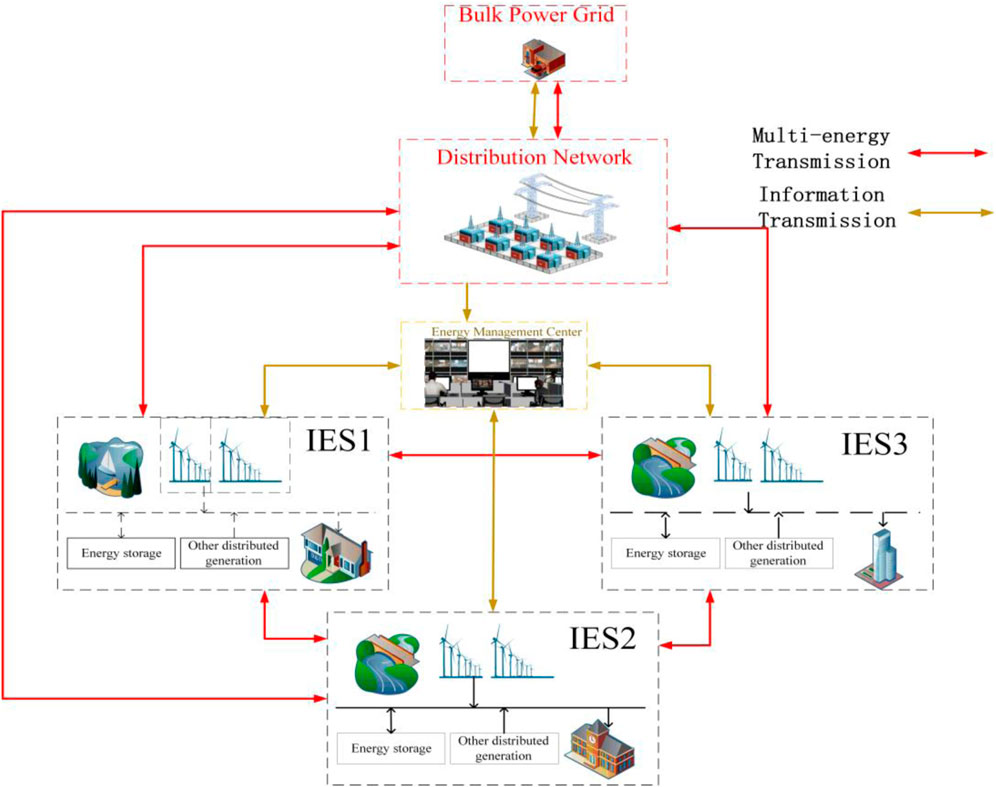
FIGURE 1. Allowable framework for distribution network optimization considering energy sharing among multiple subsystems.
It can be seen from Figure 1 that water-electric-gas integrated energy subsystems, which are studied herein, can complement each other in terms of energy utilization. By coordinating the characteristics of net load in each subsystem, energy can be shared among and absorbed within the multi-subsystem group. The large power grid operator, the distribution network operator and the multi-water-electric-gas IES group are all equipped with information sharing devices, covering price information, energy sharing information, cost sharing information, etc.
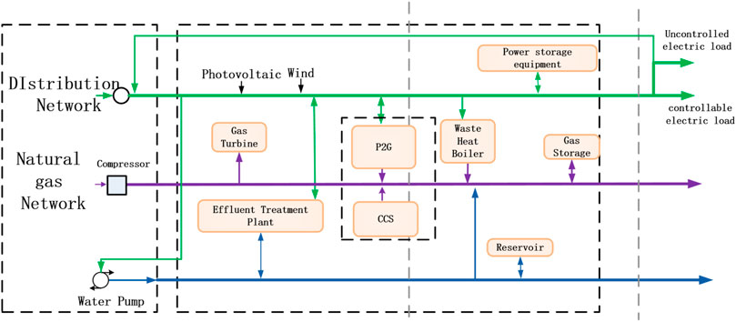
A water-electric-gas integrated energy subsystem mainly consists of the photovoltaic electricity generation device, the wind power device, the carbon capture device, the gas-fired unit, the electric-to-gas converter, the water-electric cogeneration unit, the wastewater electricity generation device, the energy storage device and other devices. The basic frame-work of the system is shown in Figure 2.
In this system, the photovoltaic electricity generation device and the wind power device are renewable energy sources and use natural resources to generate electricity. The electric-to-gas converter can generate hydrogen (H2) and oxygen (O2). Hydrogen generated can be transmitted to the hydrogen refueling station for the use by fuel cell vehicles. It can also be used to further synthesize methane (CH4), which is directed to natural gas pipelines to promote the absorption of clean energy. The carbon capture device can absorb the carbon dioxide generated from electricity generation, thereby reducing the cost of treating carbon dioxide. The water-electric cogeneration unit can generate water power and electric power simultaneously, between which there is a strong constraint. The wastewater utilization device can generate electricity from surplus wastewater and produce electric power, thus realizing the conversion of water resources to electric energy. The energy storage device can perform the transfer of energy in time and effectively improve the flexibility of energy in the system. Meanwhile, flexible adjustment or efficiency reduction feasible for different energy loads within a day, rendering comprehensive demand response.
3 Mathematical model for the game optimization and dispatching of active distribution network with multiple water-electric-gas integrated energy subsystems
In the framework of the system, there are mainly two stakeholders with game relations, namely, the distribution network operator and multiple water-electric-gas integrated energy subsystems. The specific model is as follows:
3.1 Distribution network operator
The decision variables of the distribution network operator are the internal purchasing price and the selling price, while the objective function is the profits made by trading electric energy with the large power grid and multiple subsystems, as follows:
where
In addition, in order to ensure the reasonableness of the prices set by the distribution network operator and prevent malicious price increases for prof-it-making, it is necessary to consider the price regulatory constraint from policy, as follows:
Considering the rationality of the profit-making de-mand of the distribution network operator, the internal electricity prices formulated should also meet the following requirement:
3.2 Multiple water-electric-gas integrated energy subsystems
Multiple water-electric-gas integrated energy sub-systems are interconnected through power lines or energy pipelines, so that it is possible to realize the transfer and absorption of energy among different subsystems during different periods. The objective function is the overall operating cost of the system cluster, which is specifically shown as follows:
where
Each factor considered in the system cluster is as follows:
3.2.1 Gas-fired unit
The specific cost of the gas-fired in the subsystem
where
The operational constraint is as follows:
where
3.2.2 Water-electric cogeneration
Similar to heat-electric cogeneration, water-electric cogeneration can generate water energy and electric energy simultaneously by consuming a certain amount of fuel. Generally, the cost of fuel consumed by the water-electric cogeneration unit is related to the output water power and electric power. The cost of fuel is shown as follows:
where
The operational constraint is as follows:
where
3.2.3 Transaction cost
The transaction cost of the subsystem
where
The operational constraint is as follows:
where
3.2.4 Wastewater utilization device
The wastewater utilization device, which adopts biological treatment process, can remove toxic sub-stances in organic wastewater and recycle organic wastewater. In view of the conversion characteristic of the wastewater utilization device, that is, the conversion efficiency should be considered in con-version by the device, the conversion cost is simplified in this paper through the conversion efficiency. The relationship between the water power output by the wastewater utilization device and the electric power consumed is as follows:
where
3.2.5 Electric-to-gas converter
The electric-to-gas converter can generate hydrogen and oxygen. Hydrogen can be transmitted to the hydrogen refueling station for the use by fuel cell vehicles. It can also be used to further synthesize methane (CH4), which is directed to natural gas pipelines. On the one hand, the electric-to-gas converter can use surplus electric energy generated from clean energy in the case of abundant energy supply, to electrolyze water and generate a large amount of oxygen and hydrogen. On the other hand, it can also work as an electric-to-methane converter to absorb carbon dioxide and generate methane fuel and water.
The operational constraint is as follows:
where
3.2.6 Energy storage device
The energy storage system can realize the transfer of energy in time and effectively improve the flexibility of energy in the system. When participating in the coordination and optimization of operation in the access system, the energy storage device would incur the operating cost, as follows:
The operational constraint is as follows:
where
3.2.7 Water pump device
The water pump is an independent component in the water network, which only produces and supplies water. The operating cost of the water pump in the subsystem
where
3.2.8 Carbon capture device
The carbon capture device can capture carbon dioxide emitted and reduce the cost of exhaust emission from the system. The specific constraint is as follows:
where
3.2.9 Demand response
The electric-gas-water integrated energy demand load can be divided into rigid load not participating in demand response and flexible load participating in demand response. From the perspective of energy characteristics, electricity, gas and water have different energy consumption characteristics. Therefore, transfer is adopted for electricity and gas, and efficiency reduction is adopted for water. The electric, gas and water loads after participating in demand response are as follows:
where
The total amount of flexible load remains unchanged throughout the demand response process:
The percentage of decrease/increase in electric, gas and water load shall meet the following constraint:
where
All kinds of factors in the general water-electric-gas IES are described in detail above. In addition, multiple energy sources including electricity, gas and water in each subsystem also need to meet the balance of energy, which is not repeated here.
4 Analysis and solution of the game relationship between players
4.1 Game relationship between players
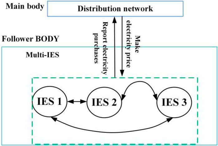
On the basis of the model above, further analysis is made on the game relationship between the main players: the distribution network operator has priority in formulating electricity prices, and the multi-subsystem group at the lower layer need to respond to the amount of electricity traded according to the internal electricity prices set by the upper-layer distribution network operator. The amount of electricity traded determines the objective function of the upper layer. In addition, the strategies made by these two players are prioritized, that is, they are not equal in status. Therefore, the upper-layer distribution net-work operator and the lower-layer multi-subsystem group constitute a Stackelberg game model. For the lower layer, subsystems can engage in energy sharing, which belongs to the category of cooperative game. To sum up, the upper and lower layers constitute a hybrid game model, and the framework of the game relationship between stakeholders in the system is shown in Figure 3.
What needs further discussion is that the respective benefits of multiple subsystems at the lower layer need to be shared and balanced. The common methods to solve this problem include Shapley value, Nash bargaining, nucleolus, etc. Among them, the method of asymmetric Nash bargaining is not affected by the number of participants, takes the contribution of each participant into careful consideration, and has been applied to multiple cooperation scenarios. The specific model is as follows:
where
where
Formula (26) is mathematically converted, and the two convex sub-problems after conversion are shown in Formulas 30, 31 respectively:
where
4.2 Solution method
The process of solving for the model is designed based on the previous analysis of the game relationship between players in the system framework. Generally, there are two methods for the issue of double-layer optimization: 1) using KKT conditions to transform a lower-layer problem into an optimization problem with only constraints and connecting to the upper layer for simultaneous solution; 2) using an intelligent algorithm and solver to solve the problem iteratively. It can be found that there are a large number of 0–1 variables in the lower-layer problem. Accordingly, the lower-layer problem is a mixed-integer problem that is non-convex, where KKT conditions cannot be used. Therefore, the second method is adopted. It should be noted that the upper layer of this model has strategy constraints, so that the algorithm needs to be modified before being applied to this model.
(1) Setting parameters: an intelligent algorithm with constraints is designed through modifying the genetic algorithm, setting relevant parameters in the modified genetic algorithm and initializing the system parameters;
(2) Optimizing the upper layer: an initial uncertainty set population is encoded and formed by randomly generating sets of internal electricity prices by the distribution network operator under constraints (4–5), and transferring the internal electricity price sets to the lower-layer sub-problem;
(3) Optimizing the lower layer: the CPLEX solver is used to optimize the solution of the lower-layer multi-subsystem group, obtain the dispatching plan of each device in the multi-subsystem group and the amount of electricity traded with the upper layer through coupling, and record the strategy and objective function value of each subsystem;
(4) Recursively calculating the upper-layer objective function: the amount of electricity traded with the upper layer is returned to the upper layer to calculate the current income of the upper layer;
(5) Updating internal electricity prices: the current optimal solution (i.e., the worst scenario) is updated and replaced with the largest
(6) Determining convergence: If the convergent
(7) Finishing optimum seeking
5 Example analysis
5.1 Example setting
The scenarios considered cover three water-electric-gas IESs. The reference source for the scenario considered in this paper is the actual project data of a region in southern China (Mohammadi et al., 2017). The specific parameters are: the upper and lower limits of P2G output are 800 kW and 0 respectively, with the efficiency being 60%; the upper and lower limits of carbon capture output are 100 kW and 0 respectively, with the carbon dioxide capture rate being 90% and the emission intensity being is 0.2; the electric, gas and water loads can be adjusted within a certain range, with the total amount of electric and gas loads before and after adjustment remaining unchanged, the maximum allowable adjustment proportion of electric and gas loads in each period within a day being 5% and 3% respectively, and the upper limit of efficiency reduction of water load being 10%; the rated capacity and upper limit of charging and discharging power of the energy storage battery are 300 kW h and 60 kW respectively, with the maximum and minimum values of the state of charge being 0.9 and 0.1 respectively, the initial value of the state of charge being 0.2, and the charging and discharging efficiency coefficients both being 0.95; the rated capacity and upper limit of gas storage and discharging efficiency of the gas tank are 60 kW h and 12 kW respectively, with the maximum and minimum values of the state of charge being 0.9 and 0.1 respectively, the initial value of the state of charge being 0.5, and the charging and discharging efficiency coefficients both being 0.95; the electric-water ratio of the water-electric cogeneration unit is 1.5, with the electric-to-gas efficiency and wastewater electricity generation efficiency being 95% and 90% respectively; the cost coefficients of water-electric cogeneration unit 1 are 0.0004433 yuan/kW, 0.003546 yuan/kW, 0.007093 yuan, −1.106 yuan/kW, −4.426 yuan/kW and 737.4 yuan respectively, with the maximum and minimum electric outputs being 800 kW and 160 kW respectively, the maximum and minimum water outputs being 200 and 30 kW respectively, the upper and lower limits of the climbing rate being 9 kW/s and 4 kW/s; the cost coefficients of water-electric cogeneration unit 2 are 0.0007881 yuan/kW, 0.006305 yuan/kW, 0.01261 yuan, −1.475 yuan/kW, −5.901 yuan/kW and 737.4 yuan respectively, with the maximum electric output and minimum electric outputs being 600 and 120 kW respectively, the maximum and minimum water outputs being 150 and 23 kW respectively, and the upper and lower limits of the climbing rate being 9 kW/s and 4 kW/s; the cost coefficients of the water pump are 0.00018 yuan/kW2, 0.0374 yuan/kW, and 0 respectively, with the maximum and minimum outputs being 250 kW and 0 respectively. The predicted values of renewable energy output and load in the three subsystems are shown in Figure 4.
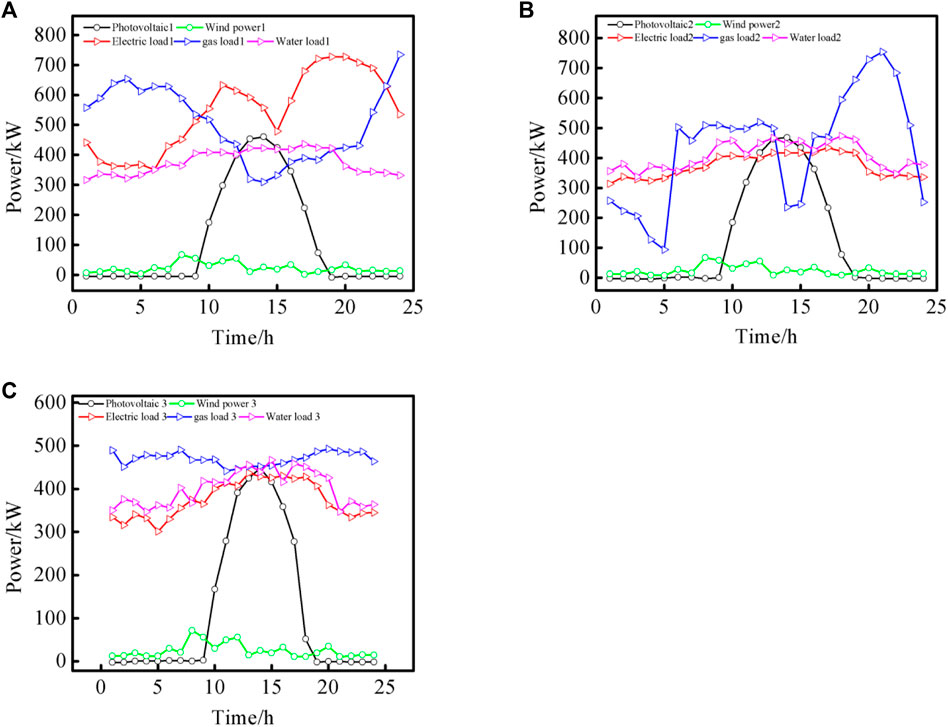
FIGURE 4. Predicted values of renewable energy output and load in the three subsystems. (A): Predicted values of renewable energy output and load in Subsystems 1. (B): Predicted values of renewable energy output and load in Subsystems 2. (C): Predicted values of renewable energy output and load in Subsystems 3.
5.2 Example results
Under the compiling environment of MATLAB 2021a, Yalmip language is used in this paper to call CPLEX for solution.
To verify the effectiveness of the model proposed in this paper, the following three scenarios are set:
Scenario 1: Each subsystem operates independently and trades directly with the large power grid.
Scenario 2: Each subsystem operates cooperatively and trades directly with the large power grid.
Scenario 3: Each subsystem operates cooperatively and engages in a Stackelberg game with the distribution network operator.
Table 1 shows the income of the distribution network operator, the total operating cost of subsystems and the cost of carbon emission under the three scenarios.

TABLE 1. Income of the distribution network operator, total operating cost of subsystems and total cost of carbon emission under the three scenarios.
It can be seen from Table 1 that the total operating cost of the multi-subsystem group is the highest un-der Scenario 1, and the total cost of carbon emission is also the highest. The reason is that under this scenario, the three subsystems cannot share energy with each other, resulting in the worst flexibility of the system and the highest operation cost. Compared with Scenario 1, the total cost of the multi-subsystem group is reduced under Scenario 2, and the total cost of carbon emission is reduced to 0. This is because the energy sharing between subsystems further consumes renewable energy within the system, reduces the cost of trading with the large power grid, and gives full play to the role of the electric-to-gas converter and carbon capture device in the system. Under Scenario 3, due to the participation of the distribution network operator in the mechanism of the Stackeberg game with the multi-subsystem group, they can both make profits under the effect of the internal electricity prices set by the upper-layer operator, which further reduces the total operating cost of the multi-subsystem group and creates prof-it-making space for the distribution network operator.
The modified method of Nash bargaining described above is used to redistribute the income of each subsystem to balance the income of all players involved in the cooperative game. In particular, multiple subsystems at the lower layer are in a cooperative mode under Scenario 2 and Scenario 3. Tables 2, 3 respectively show the process of allocating for the three subsystems.
Tables 2, 3 specifically show the process of the three subsystems bargaining over cost redistributing under Scenario 2 and Scenario 3. The contribution of each subsystem is specifically considered in the process of the three subsystems bargaining over cost redistributing. After bargaining, the cost of each subsystem is reduced compared with the cost under independent operation, which improves the stability of each subsystem participating in the alliance. As the cost redistributing process under Scenario 2 is similar to that under Scenario 3, the analysis is carried out based on the results in Table 3: under Scenario 3, the cooperation surplus of Subsystem 1, Subsystem 2 and Subsystem 3 is 342.41 yuan, 103.14 yuan, and 379.54 yuan respectively, which indicates that Subsystem 3 has the largest contribution in the process of energy sharing, followed by Subsystem 1, and finally by Subsystem 2. The redistributing result is determined by the mutual contribution of each subsystem in the process of energy sharing, to reasonably and orderly balance the operating costs of the three subsystems.
It can be seen from Figures 5, 6 that the distribution network operator determines the optimal internal electricity prices based on the boundary of the purchasing and selling prices offered by the large power grid and the response of the lower-layer multi-subsystem group to the amount of electricity. Within this framework of internal electricity prices, Subsystem 1 characterizes electricity sales at 3:00–7:00 and 11:00–16:00 in a day; Subsystem 2 mainly characterizes electricity sales at 12:00–16:00 in a day; meanwhile, Subsystem 3 mainly presents the state of electricity purchase. This is determined by the initial renewable energy and load characteristics of the three subsystems. The specific amount of electricity traded with the distribution network operator is determined by the internal electricity price game established by the upper-layer distribution network operator. For example, the distribution network operator sets a higher purchasing price during 12:00–15:00 to guide lower-layer multiple subsystems to sell electricity.
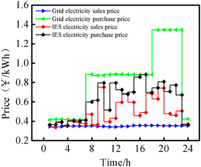
FIGURE 5. Optimized internal electricity prices set by the distribution network operator under game equilibrium.
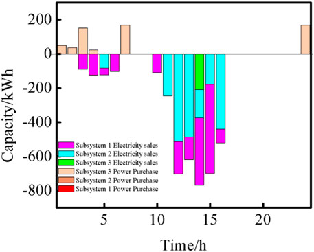
FIGURE 6. Amount of electricity traded between the three subsystems and the upper-layer distribution network when the upper and lower layers reach equilibrium.
Subsystem 1 among the three subsystems is taken as an example and the focus in the analysis. Figure 7 shows the plan curve of dispatching the three energy sources for each device in Subsystem 1.
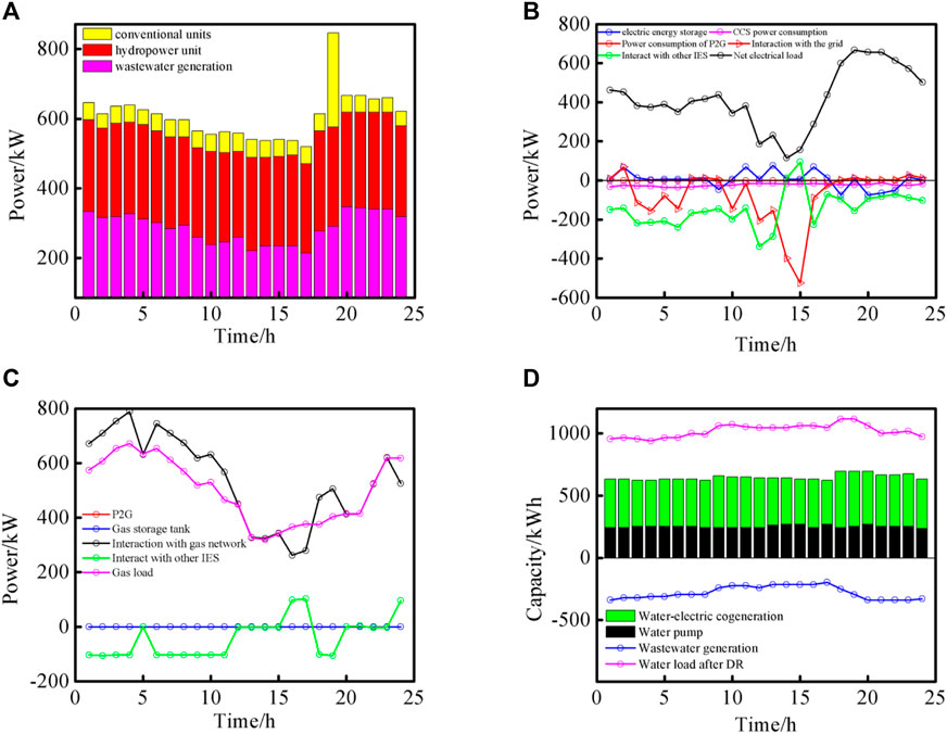
FIGURE 7. Plan of dispatching the three energy sources for each device in Subsystem 1. (A): Plan of dispatching for unit equipment. (B): Plan of dispatching for electric energy related equipment. (C): Plan of dispatching for gas energy related equipment. (D): Plan of dispatching for water energy related equipment.
Figure 8 shows the curve of changes of the response to electric, gas and water load demands in Subsystem 1 under Scenario 3.
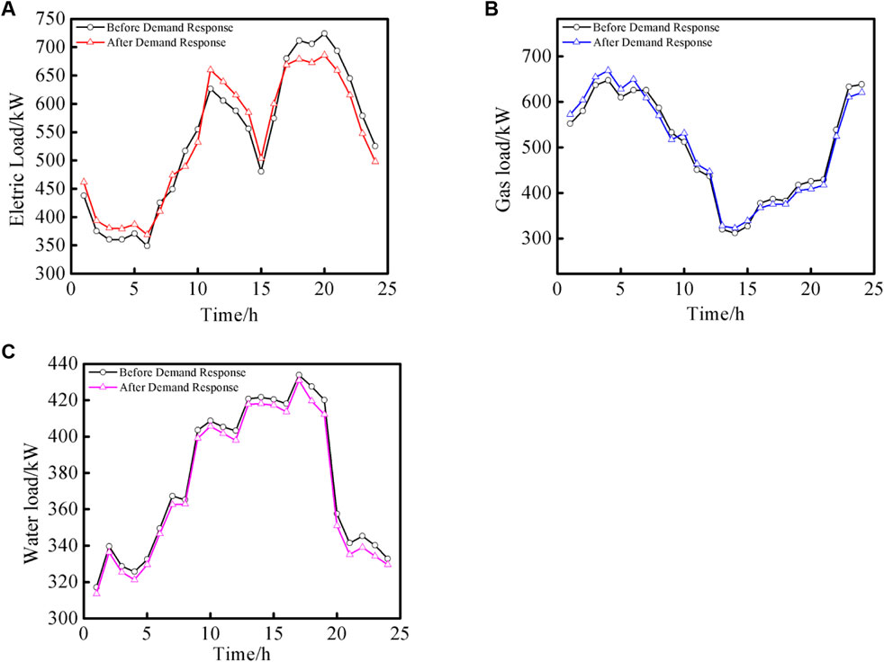
FIGURE 8. Changes of response to electric, gas and water load demands in Subsystem 1. (A): Changes of response to electric load demands in Subsystem 1. (B): Changes of response to gas load demands in Subsystem 1. (C): Changes of response to water load demands in Subsystem 1.
According to Figure 8, the electric and gas loads in Subsystem 1 can be transferred at different times in a day. Specifically, electric load is taken as an example of transferable load: the efficiency of electric load is performed reduced at 18:00–24:00 of the day, but increased at 0:00–6:00 and 11:00–15:00 of the day to some extent. The reason is that Subsystem 1 needs to consider transferring the periods in which the operation of each unit, the amount of electricity traded and other items constitute a higher total cost to the periods incurring a lower cost, so as to improve the economic performance of the system. For water load of which efficiency can be reduced, decision-makers need to find a balance point between the cost of efficiency reduction and the economic benefits that can be brought by efficiency reduction, so as to optimize the economic performance of the system.
In order to further explore the influence of the uncertainty of the predicted values of photovoltaic power generation and wind power generation on the mathematical model of this paper, the method of positive distribution is used to set the initial 200 sets of uncertain scene sets. The results of the deterministic model and the uncertainty model are shown in Table 4.
According to Table 4, it can be concluded that the income of distribution network operators is reduced and the total operating cost of subsystems is increased in the uncertain scenario. This is because the scheduling strategy of the system is more difficult to carry out in the uncertain scenario, that is, the external uncertainty interferes with the operating efficiency of the system.
In order to further explore the influence of static security constraints of power system (branch overload constraints and bus voltage over-limit constraints) on the mathematical model of this paper, static security constraints are added to the original mathematical model. The results before and after the addition are shown in Table 5.
According to Table 5, it can be obtained that the revenue of distribution network operators and subsystem group operators in the system is forced to decrease under the scenario of considering grid constraints. This is because considering the static security constraints of the power system will force the feasible region of the scheduling strategy variables in the system to decrease, and the optimal solution of the system will shift, that is, the operation of the system will become more demanding under this condition.
6 Conclusion
This paper examines the hierarchical relationship between multiple stakeholders in the system, and proposes a hybrid game model for distribution network and multiple systems based on cooperative and non-cooperative game strategies. The conclusion are as follows:
(1) In this paper, a Stackelberg game model is established for distribution network and multiple subsystems. By solving the Stackelberg equilibrium, the equilibrium points for both sides are obtained, so as to better measure the interest relationship between them and improve the energy sharing between upper and lower layers;
(2) Under the framework proposed, the energy sharing model for subsystems is established under the guidance of cooperative game theory, which is conducive to improving the capacity of local energy consumption among regional subsystems and reducing the economic losses caused by the status ad-vantage of the upper-layer distribution network operator;
(3) The model proposed in this paper takes into ac-count multiple factors including demand response, carbon capture, electric-to-gas, water-electric cogeneration and wastewater electricity generation, enriching the complexity of the model and providing decision-makers with dispatching plans in complex environments;
(4) The incorporation of energy sharing between the water system and multiple subsystems can maximize the use of energy in the system, improve the overall economic benefits, and achieve win-win benefits for multiple players in the system.
Data availability statement
The original contributions presented in the study are included in the article/Supplementary Material, further inquiries can be directed to the corresponding author.
Author contributions
ZS: Conceptualization, Data curation, Methodology, Writing–original draft, Writing–review and editing. WH: Formal Analysis, Investigation, Software, Writing–original draft. GZ: Funding acquisition, Project administration, Resources, Visualization, Writing–review and editing. MZ: Data curation, Formal Analysis, Methodology, Supervision, Writing–review and editing. ZB: Data curation, Formal Analysis, Project administration, Software, Writing–review and editing. XL: Investigation, Methodology, Software, Supervision, Writing–original draft.
Funding
The author(s) declare that no financial support was received for the research, authorship, and/or publication of this article.
Conflict of interest
The authors declare that the research was conducted in the absence of any commercial or financial relationships that could be construed as a potential conflict of interest.
Publisher’s note
All claims expressed in this article are solely those of the authors and do not necessarily represent those of their affiliated organizations, or those of the publisher, the editors and the reviewers. Any product that may be evaluated in this article, or claim that may be made by its manufacturer, is not guaranteed or endorsed by the publisher.
References
Bao, M., Hui, H., Ding, Y., Sun, X., Zheng, C., and Gao, X. (2023). An efficient framework for exploiting operational flexibility of load energy hubs in risk management of integrated electricity-gas systems. Appl. Energy 338, 120765. doi:10.1016/j.apenergy.2023.120765
Chis, A., and Koivunen, V. (2019). Coalitional game-based cost optimization of energy portfolio in smart grid communities. IEEE Trans. smart grid 10 (2), 1960–1970. doi:10.1109/tsg.2017.2784902
Chis, A., Lunden, J., and Koivunen, V. (2017). “Coalitional game theoretic optimization of electricity cost for communities of smart households,” in Proceedings of the IEEE International Conference on Acoustics, New Orleans, LA, USA, 05-09 March 2017.
Duan, S., Sui, H., and Zhang, S. (2021). “Orderly charging strategy for electric vehicles based on master-slave game,” in Proceedings of the 2021 IEEE/IAS Industrial and Commercial Power System Asia (I&CPS Asia), Chengdu, China, 18-21 July 2021.
Hu, C., Luo, Z., Zhou, S., Xie, H., and Hu, L. (2019). “Optimal dispatch model of wind power accommodation in combined heat and power system based on unit commitment,” in Proceedings of the 2019 IEEE Innovative Smart Grid Technologies - Asia (ISGT Asia), Chengdu, China, 21-24 May 2019.
Hu, J., Liu, X., Shahidehpour, M., and Xia, S. (2021). Optimal operation of energy hubs with large-scale distributed energy resources for distribution network congestion management. IEEE Trans. Sustain. Energy 12 (3), 1755–1765. doi:10.1109/TSTE.2021.3064375
Hui, H., Bao, M., Ding, Y., and Song, Y. (2022). Exploring the integrated flexible region of distributed multi-energy systems with process industry. Appl. Energy 311, 118590. doi:10.1016/j.apenergy.2022.118590
Li, G., Zhang, R., Jiang, T., Chen, H., Bai, L., Cui, L., et al. (2017). Optimal dispatch strategy for integrated energy systems with CCHP and wind power. Appl. Energy 192, 408–419. doi:10.1016/j.apenergy.2016.08.139
Li, N., Zhao, X., Shi, X., Pei, Z., Mu, H., and Taghizadehhesary, F. (2021). Integrated energy systems with CCHP and hydrogen supply: A new outlet for curtailed wind power. Appl. Energy 303, 117619. doi:10.1016/j.apenergy.2021.117619
Li, Z., and Ma, T. (2020). Peer-to-peer electricity trading in grid-connected residential communities with household distributed photovoltaic. Appl. Energy 278, 115670. doi:10.1016/j.apenergy.2020.115670
Mohammadi, M., Noorollahi, Y., Mohammadi-Ivatloo, B., and Yousefi, H. (2017). Energy hub: from a model to a concept - a review. Renew. Susstainable Energy Rev. 80, 1512–1527. doi:10.1016/j.rser.2017.07.030
Tushar, W., Saha, T. K., Yuen, C., Morstyn, T., Al-Masood, N., Poor, H. V., et al. (2019). Grid influenced peer-to-peer energy trading. IEEE Trans. Smart Grid 11 (2), 1407–1418. doi:10.1109/tsg.2019.2937981
Wang, R., Cheng, S., Zuo, X., and Liu, Y. (2022). Optimal management of multi stakeholder integrated energy system considering dual incentive demand response and carbon trading mechanism. Int. J. Energy Res. 46, 6246–6263. doi:10.1002/er.7561
Wang, S., Hui, H., Ding, Y., Ye, C., and Zheng, M. (2023). Operational reliability evaluation of urban multi-energy systems with equivalent energy storage. IEEE Trans. Industry Appl. 59 (2), 2186–2201. doi:10.1109/tia.2022.3232099
Wang, S., Zhai, J., and Hui, H. (2020). Optimal energy flow in integrated electricity and gas systems with injection of alternative gas. IEEE Trans. Sustain. Energy 14 (3), 1540–1557. doi:10.1109/tste.2023.3237229
Zhang, F., Salimu, A., and Ding, L. (2022). Operation and optimal sizing of combined P2G-GfG unit with gas storage for frequency regulation considering curtailed wind power. Int. J. Electr. power energy Syst. 141, 108278. doi:10.1016/j.ijepes.2022.108278
Keywords: water system, water-electric cogeneration, energy sharing, Stackelberg game, low-carbon dispatching, cooperative game
Citation: Shi Z, Han W, Zhang G, Zhu M, Bai Z and Lv X (2023) Research on energy sharing between distribution network and multiple systems based on the mixed game strategy and water-electric-gas integrated energy complementation. Front. Energy Res. 11:1268774. doi: 10.3389/fenrg.2023.1268774
Received: 28 July 2023; Accepted: 28 August 2023;
Published: 07 September 2023.
Edited by:
Minglei Bao, Zhejiang University, ChinaReviewed by:
Sheng Wang, University of Macau, Macau SAR, ChinaJiongcheng Yan, Shandong University, China
Copyright © 2023 Shi, Han, Zhang, Zhu, Bai and Lv. This is an open-access article distributed under the terms of the Creative Commons Attribution License (CC BY). The use, distribution or reproduction in other forums is permitted, provided the original author(s) and the copyright owner(s) are credited and that the original publication in this journal is cited, in accordance with accepted academic practice. No use, distribution or reproduction is permitted which does not comply with these terms.
*Correspondence: Guangming Zhang, emdtQG5qdGVjaC5lZHUuY24=
 Zhihan Shi1
 Xiaodong Lv