 Qi-Jian Chen1
 Xing-Kang Su
 Long Gu
95% of researchers rate our articles as excellent or good
Learn more about the work of our research integrity team to safeguard the quality of each article we publish.
Find out more
ORIGINAL RESEARCH article
Front. Energy Res. , 22 September 2023
Sec. Nuclear Energy
Volume 11 - 2023 | https://doi.org/10.3389/fenrg.2023.1259254
This article is part of the Research Topic Experimental and Simulation Research on Nuclear Reactor Thermal-Hydraulics, Volume II View all 9 articles
The present study focuses on the thermal hydraulic characteristics of fuel assemblies in the China Initiative Accelerator Driven subcritical System (CiADS), which utilizes grid-type spacers to support lead bismuth eutectic (LBE) cooled fast reactors. While the structural design and mechanical analysis of CiADS triangular fuel assemblies with grid-type spacers have been preliminarily investigated, there is a pressing need to study the thermal hydraulic behavior of liquid LBE within these fuel assemblies. This analysis is crucial for assessing the safety and economy of the CiADS subcritical reactor. The sub-channel analysis code, based on the lumped parameter method, plays a vital role in rapidly evaluating the safety features of LBE-cooled fast reactor fuel assemblies. To comprehensively evaluate the thermal hydraulic performance of fuel assemblies with grid-type spacers in the CiADS LBE cooling system, the flow pressure drop model, turbulent mixing model, and convective heat transfer model for the fuel assembly structure with grid-type spacers were incorporated into the existing CiADS sub-channel analysis code. This enhanced code has been successfully employed in the thermal hydraulic analysis of fuel assemblies utilizing wire-type spacers in the CiADS system. To verify the validity and accuracy of the modified CiADS sub-channel analysis code in calculating triangular fuel assemblies with grid-type spacers, the code was first utilized to replicate a 19-rods flow heat transfer experiment with grid-type spacers cooling liquid LBE. A comparison between the simulation and experimental results confirms that the CiADS sub-channel analysis code can predict the coolant temperature and fuel rod surface temperature in fuel assemblies with grid-type spacers. Subsequently, the structure and thermal hydraulic design of the latest CiADS fuel assembly with grid-type spacers were reviewed. Finally, taking into account the aforementioned enhancements to the CiADS sub-channel analysis code, a comprehensive thermo-hydraulic calculation of the CiADS fuel assembly with grid-type spacers was conducted. The results demonstrate that the coolant outlet temperature, maximum cladding temperature, and maximum fuel pellet temperature all fall within the design parameters of CiADS. Furthermore, the impact of the number of rods in different rod bundles (91, 61, 37, and 7 rods) on thermal hydraulic performance was analyzed. The findings indicate that, while ensuring calculation accuracy and efficiency, the results obtained from the 37-rod bundle can effectively reflect the thermal hydraulic behavior of the reactor core.
Liquid lead and lead bismuth eutectic (LBE) are emerging as promising coolants for next-generation advanced nuclear energy systems, primarily due to their superior thermal-hydraulic properties, increased inertness, and optimal neutron characteristics (Abram and Ion, 2008). Both the China Initiative Accelerator Driven Subcritical System (CiADS) (Gu and Su, 2021) and the Multi-purpose Hybrid Research Reactor for High-tech Applications (MYRRHA) (Abderrahim et al., 2012) have identified liquid LBE as the preferred coolant in their subcritical reactors. The CiADS project, however, faced technical and engineering challenges. This led to the formulation of two distinct fuel assembly designs: wire-type spacers and grid-type spacers. The aim was to thoroughly assess and integrate these designs into the CiADS framework. Initial research was directed toward the design and thermal-hydraulic engineering of LBE-cooled fuel assemblies using wire-type spacers (Peng et al., 2017). Recent developments in the structural design of the CiADS triangular fuel assembly with wire-type spacers were highlighted by Yu et al. (2021). Furthermore, Fan et al. (2020) embarked on flow experiments with wire-wrapped 19-rod bundles tailored for CiADS. Using the Reynolds analogy and visualization methods, they derived the flow pressure drop and cross-sectional pressure drop profiles for the wire-type spacer’s fuel assembly. On the computational side, Liu et al. (2022) fine-tuned a sub-channel analysis code for simulating thermo-hydraulics of wire-type spacer fuel assemblies cooled by liquid LBE. Leveraging this code, they analyzed the thermo-hydraulic characteristics of a comprehensive 61-rod wire-type spacers fuel assembly.
Wire-type spacers play a pivotal role in preserving the ideal spacing of fuel rods, curtailing mechanical vibrations, bolstering turbulent mixing among sub-channels, and avoiding temperature peaks. However, these spacers increase flow resistance. Conversely, grid-type spacers, with their compact volume, permit a more substantial core allocation for fuel, thereby amplifying the breeding ratio and diminishing the doubling time. Furthermore, the built-in flow channels in the fuel assembly are straightforward, reducing flow resistance and the risk of obstructions from LBE corrosion impurities. Preliminary research at CiADS has addressed the structural design and the hydrostatic and dynamic attributes of the triangular fuel assembly with grid-type spacers (Sheng, 2022). It is imperative now to delve deeper into the thermal hydraulics of liquid LBE within this structure, ensuring alignment with CiADS thermal design norms. The sub-channel analysis method strikes a balance between the detailed three-dimensional computational fluid dynamics approach and the simplified one-dimensional system safety assessment, offering an efficient, cost-effective, and swift assessment of LBE’s thermal hydraulics in the fuel assembly. Several renowned codes cater to the thermal hydraulic evaluation of liquid metal-cooled fast reactors: 1) COBRA-WC (George et al., 1980), which can simulate multiple fuel assemblies at the same time as well as several operating conditions including forced and natural cycles. 2) MATRA-LMR (Kim et al., 2002), which uses the distributed resistance model and improves the sodium properties, heat transfer relations and pressure drop relations. 3) ATHAS-LMR (Chen, 2012), which deduces a three-dimensional drag model instead of the lumped parameter method by theory, and finally calculates the experimental results of the flow blockage accident in the liquid metal fast neutron breeder reactor. The results show that the calculated results are in good agreement with the experimental results. 4) SACOS-PB (Wang et al., 2013a), which is concluded that the hexagonal fuel assembly is the best choice for the LBE fast reactor by analyzing the temperature distribution of the fuel assembly and diverse component types. Wu et al. (2021) improved SACOS-PB, and Wang et al. (2021) utilized it for flow blockage incident analysis. 5) ANTEO+ (Lodi et al., 2016a), which can be used to calculate liquid metal cooled fast reactors, including sodium, lead, LBE, and is suitable for a variety of geometric structures such as bare-rod, grid-type spacers, and wire-type spacers. 6) KMC-sub (Li et al., 2017), which adds the relation applicable to liquid LBE and is used to calculate the steady-state condition of SNCLFR-100. (7)
Conducting heat transfer experiments using LBE is challenging due to its corrosive and opaque nature (Schroer et al., 2012). For the purpose of generating experimental data and validating sub-channel analysis codes specifically designed for LBE-cooled fuel assemblies with spacer grids, several notable experiments have been undertaken: 1) Pacio et al. (2014) constructed the THEADES loop at the Karlsruher Liquid Metals Laboratory (KALLA) with reference to the geometry of MYRRHA. They used 19 rods with grid-type spacers and conducted heat transfer experiments under steady-state and forced convection conditions. 2) Di Piazza et al. (2016) also carried out a heat transfer experiment with 19 rods using wire-type spacers in the NACIE-UP circuit for the MYRRHA reactor. Unlike the experiments by Pacio et al., the NACIE-UP loop experiments adopted steady-state, adiabatic, and natural cycles, and placed more focus on the heat transfer phenomenon of liquid LBE at a low flow rate (Re = 1000–10000). 3) Lyu et al. (2016) carried out heat transfer experiments of 61 rods bundle wire-wrapped fuel assemblies on the KYLIN-II lead reactor comprehensive experimental circuit, in which the experimental sections included a 350 mm inlet flow section, a 800 mm heating section and a 132 mm outlet flow section, in order to eliminate the effect of inlet flow instability and outlet effect on the heating section. In these experiments, Pacio et al. carried out a detailed study on the heat transfer process of high-temperature liquid LBE in 19 rods bundle with grid-type spacers, and obtained multiple groups of coolant temperatures and heating rod temperatures, which were widely applied to the validation of sub-channel analysis code for LBE cooling.
Since most of the sub-channel analysis code are closed-source, for the sake of studying the thermal hydraulic characteristics of CiADS LBE cooling fuel assemblies with grid-type spacers, this study is based on the optimization of the sub-channel analysis code for LBE cooling winding fuel assemblies with grid-type spacers by Liu et al. (2022). By incorporating flow pressure drop, convective heat transfer, and turbulent mixing models suitable for the fuel assembly with grid-type spacers cooled by lead and bismuth, the code’s development aims to analyze the thermal hydraulics of the CiADS lead and bismuth-cooled fuel assembly with grid-type spacers. The validity and reliability of the sub-channel analysis code developed in this study were verified by using the available information of 19 rods with grid-type spacers heat transfer experiments cooled by lead and bismuth. Then, based on the current version of the sub-channel analysis code, the thermal hydraulic behavior of coolant temperature, cladding temperature and fuel rod temperature distribution for a single CiADS full-size fuel assembly with grid-type spacers was investigated. Previously, the latest structural design and thermal hydraulic of the current CiADS LBE cooled fuel assemblies with grid-type spacers were reviewed. Finally, the influence of different rod numbers on the internal temperature distribution characteristics of the fuel assembly is analyzed. By incorporating the flow pressure drop model, convective heat transfer model, and turbulent mixing model suitable for the fuel assembly with grid-type spacers cooled by lead and bismuth, the code’s development aims to analyze the thermal hydraulics of the CiADS lead and bismuth cooled fuel assembly with grid-type spacers. The validity and reliability of the sub-channel analysis code developed in this study were verified using the available data from heat transfer experiments involving 19 rods with grid-type spacers cooled by lead and bismuth. Subsequently, based on the current version of the sub-channel analysis code, the thermal hydraulic behavior of coolant temperature, cladding temperature, and fuel rod temperature distribution for a single full-size CiADS fuel assembly with grid-type spacers was investigated. Furthermore, the latest structural design and thermal hydraulics of the current CiADS LBE-cooled fuel assemblies with grid-type spacers were reviewed. Finally, the influence of different rod numbers on the internal temperature distribution characteristics of the fuel assembly is analyzed.
The main purpose of the sub-channel analysis code is to accurately calculate and analyze the thermal hydraulic behavior of coolant and fuel rods in fuel assemblies. Due to the significantly higher boiling point of liquid lead compared to the operating temperature within the reactor, the coolant can be treated as a single-phase flow without boiling. The code utilizes discrete mass, axial momentum, transverse momentum, and energy conservation equations to calculate the mass flow rate and temperature distribution of coolant in different sub-channels. The conservation equations for incompressible fluids are solved using the finite difference method, which ensures the conservation of the total mass entering and leaving a control volume. The thermal hydraulic parameters are then calculated using the conservation equations for mass, energy, and momentum (Liu et al., 2022).
Mass Conservation Equation:
where
Energy Conservation Equation:
where
Axial Momentum Conservation Equation:
where
Transverse Momentum Conservation Equation:
where
This chapter introduces the friction pressure drop model, convective heat transfer model, and turbulent mixing model that have been integrated into the code. Furthermore, the correlations for physical properties and fundamental numerical analysis models continue to rely on the sub-channel code COBRA-LFR developed by Liu et al. (2022).
During the calculation of sub-channel pressure drop, the overall pressure drop is divided into two components: the pressure drop across the rod bundle and the resistance pressure drop across the grid-type spacers. Attaining appropriate values for the friction coefficient and spacer loss coefficient is crucial to ensuring the accuracy of the friction pressure drop calculation. The Darcy-Weisbach formula, represented by Eq. 5, can be employed to compute the pressure drop, specifically for the rod bundle pressure drop.
Where
Many authors have conducted flow experiments on smooth rod bundles, investigated the frictional drag coefficient associated with pressure drop, and formulated suitable frictional drag patterns for various working conditions and structures. The Blasius model (Hager, 2003) and the Rehme model (Rehme, 1972) are widely used to calculate the frictional pressure drop of smooth rod bundles. The correlations are:
Blasius model:
Rehme model:
Where
Blasius model and Rehme model have been coupled into the sub-channel code.
The formula for calculating the grid-type spacers pressure drop is shown in Eq. (10), K is the spacer loss coefficient.
According to Rehme (Rehme and Trippe, 1980), the blockage of the flow cross section “e" of the spacer constitutes the main factor influencing the pressure loss, with the drag coefficient “K" being given by:
Where
Cigarini later proposed empirical correlations (Cigarini and Donne, 1988) for e and
Where
And finally:
Fuel assemblies featuring grid-type spacers are extensively utilized in various reactor types due to their straightforward design and low drag coefficient, leading to minimal pressure drop. Turbulent mixing pertains to the cross-flow mixing that arises from turbulent motion between distinct channels. The turbulent mixing coefficient (
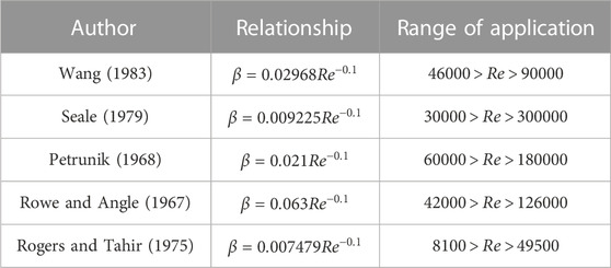
TABLE 1. Turbulent mixing model.
In the above models, the Petrunik model is applicable to the triangular fuel assembly with grid-type spacers, and the Reynolds number is close to the CiADS condition, so it is recommended for the subsequent thermal hydraulic calculation.
The heat transfer model is the most critical element for calculating fuel rod temperature in the sub-channel code. Therefore, choosing the appropriate model is pivotal for ensuring the accuracy of the sub-channel code. This study presents several widely-used heat transfer models in Table 2 and incorporates them into the sub-channel code. In 2014, J. Pacio et al. conducted an LBE heat transfer experiment and analyzed five different empirical formulas. Research indicates that the Mikityuk relationship exhibited the highest level of agreement with experimental results. The operational parameters of the CiADS triangular fuel assembly with grid-type spacers are:
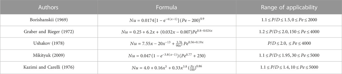
TABLE 2. Heat transfer model.
To investigate the thermal hydraulics of LBE eutectic in a reactor, a heat transfer experiment was conducted in 2016 at the KALLA Laboratory in Germany. The experiment involved a 19-rod fuel rod bundle equipped with grid-type spacers and used LBE as the coolant (Pacio et al., 2014). Over 80 different operating conditions were simulated, resulting in the collection of hundreds of experimental data points. These abundant experimental data offer valuable references for reactor design. In this study, the heat transfer experimental data from the 19-rod bundle with grid-type spacers, as conducted by Pacio, were selected as the validation benchmark. The computed data from the sub-channel analysis were compared with the experimental results to verify the accuracy of the calculations. The specific geometric parameters of the individual rods are detailed in Table 3, while the experimental conditions are outlined in Table 4. Temperature measurements were taken at distances of 532 and 855 mm from the inlet of the heated section. This is illustrated in Figure 1, which provides a visualization of the sub-channel division.
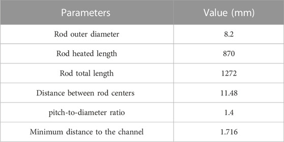
TABLE 3. Terms rod parameters.
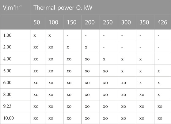
TABLE 4. Test matrix of experiments published by Pacio et al. (2014) made for different volumetric flow rate (V, m3 h−1), thermal power (Q, kW) and inlet Temperatures (T, °C). Notes:—= no experiments. × = Tin = 200°C. o = Tin = 300°C.
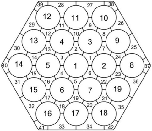
FIGURE 1. Sub-channel number and division of 19 rods.
Pacio et al. (2014) proposed a dimensionless temperature to describe the relative deviation between the temperature at the measurement location and the average temperature of the cross section. Equation 15 is used to describe this dimensionless temperature.
Where
Figures 2A–D show the calculation results, which indicate good consistency between the sub-channel code calculations and experimental results. With increasing Pe, the turbulent mixing phenomenon becomes more apparent, and the difference between the wall temperature of R1 and the average temperature of the cross section gradually decreases, as does the difference between the temperature of sub-channel 33 and the average temperature of the cross section. The red and black lines represent the fitted results for the experimental and calculated data, respectively, offering a clearer visualization of their differences. The temperature distribution within each sub-channel also becomes more uniform. These observations are consistent with the anticipated outcomes, and the discrepancy between the non-dimensional cladding temperature and the non-dimensional coolant temperature, calculated using Eq. 15, remains within 0.03. As depicted in Eq. 15, changes in the dimensionless temperature are influenced by significant fluctuations in the measured or computed temperatures. With a temperature fluctuation of 10K, the impact on the dimensionless temperature reaches 0.05. This implies that there is a 10K error between the sub-channel code calculations and the experimental results, which could arise from uncertainties in the physical property relationships utilized in the code or inaccuracies in the experimental measurement equipment.
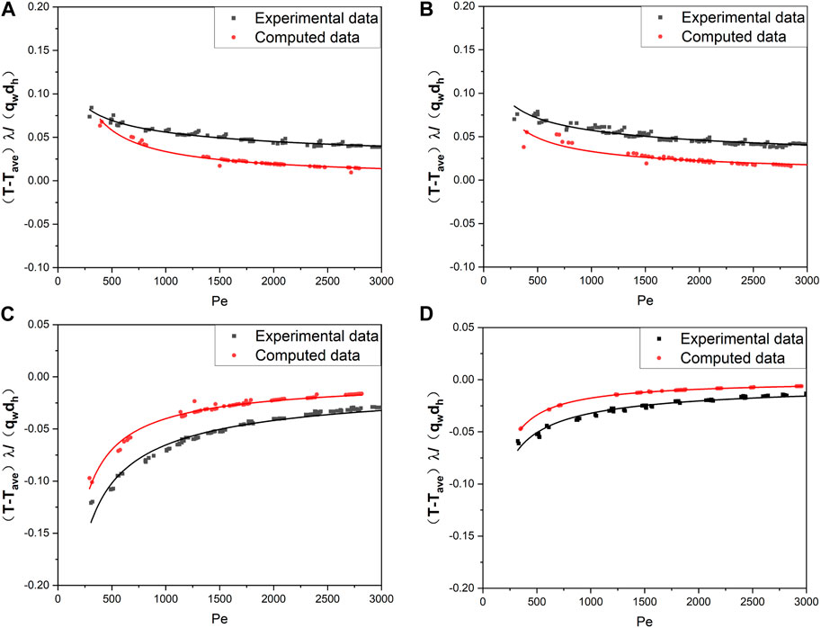
FIGURE 2. (A) R1 non-dimensional wall temperature distribution at 532 mm, (B) R1 non-dimensional wall temperature distribution in 855 mm, (C) sub-channel 33 temperature distribution in 532 mm, (D) sub-channel 33 temperature distribution in 855 mm.
As mentioned earlier, the present sub-channel code possesses the capability to precisely compute coolant temperature and cladding outer surface temperature, enabling comprehensive thermal hydraulic analysis of fuel assemblies featuring grid-type spacers. This capacity facilitates in-depth investigations into the characteristics of CiADS fuel assemblies.
The main function of CiADS subcritical reactor core is coupling with accelerator and spallation target to generate strong fast neutron field and offer an experimental setting for nuclear waste transmutation. The CiADS LBE cooled reactor is designed to operate under subcritical conditions with power regulation by the accelerator beam. The core consists of 52 hexagonal fuel assemblies, a dummy assembly and associated test channels, with a circular hole in the middle for placing spallation target tubes. The core layout of CiADS LBE cooled reactor is shown in Figure 3, and the core design parameters are shown in Table 5.
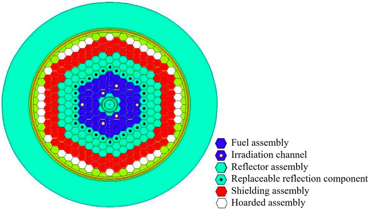
FIGURE 3. The core layout of CiADS LBE cooled reactor (Sheng, 2022)

TABLE 5. The design parameters of CiADS LBE cooled reactor core.
The fuel rod’s overall structure consists of a lower plug, cladding tube, upper plug air chamber, fuel pellet, insulation layer, and compression spring. The lower end plug and upper end plug are connected to the cladding tube’s upper and lower ends through ring welding, creating a sealed cavity. This cavity is arranged from top to bottom with an air chamber, multiple fuel pellets, a thermal insulation layer, and compression springs. The air chamber is designed to contain the gaseous fission products produced during fuel pellet operation, thereby preventing excessive internal pressure that could lead to cladding failure. The compression spring helps regulate the thermal expansion and radiation-induced swelling of the pellets. A specific amount of helium gas is filled within the fuel rods. This helium gas is situated between the fuel pellets and the inner cladding wall, enhancing heat conduction between them. Notches are present at the upper and lower ends to facilitate sliding connections with the upper and lower grids of the fuel assembly. Following established nuclear fuel production methods and related technology, fuel pellets enriched to 19.75% UO2 ceramic composition were utilized. The fundamental structure of the fuel rod is illustrated in Figure 4, and pertinent dimensional parameters are provided in Table 6.
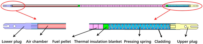
FIGURE 4. Structural composition of fuel rod (Sheng, 2022).
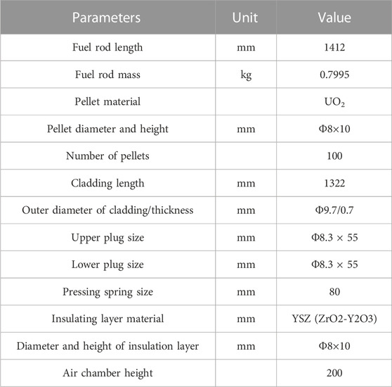
TABLE 6. Structural dimensions of the fuel rods.
The fuel assembly features a hexagonal structure and is divided into four main parts: the bottom nozzle, weight-bearing area, fuel rod bundle area, and top nozzle. Externally, the fuel assembly is composed of the bottom nozzle housing, the outer casing of the weight-bearing area, the lower grid plate of the assembly, the outer casing of the rod bundle area, the upper grid plate of the assembly, and the top nozzle housing. These components are sequentially welded and joined to form a closed structure that serves as the outer boundary of the fuel assembly. The internal structure primarily consists of three components. The first component is a push rod transmission mechanism, comprising a floating slide cylinder in the lower tube seat, a push rod, and a hook ring in the upper tube seat. This mechanism facilitates the locking and unlocking function of the fuel assembly within the reactor core. The second component comprises metal tungsten blocks within the weight-bearing area, designed to counteract the buoyancy effect of LBE on the fuel assembly. The third component is the fuel rod bundle region, which serves as the core area of the fuel assembly. Its primary role is to generate nuclear heat and transfer it to the LBE cooling medium. Figure 5 illustrates the overall structure of the fuel assembly, while Table 7 presents the parameters of the fuel assembly.
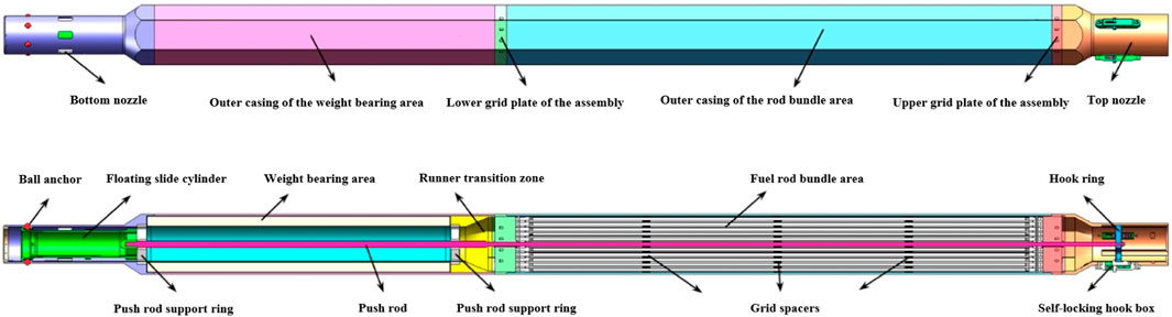
FIGURE 5. The structural composition of fuel assembly (Sheng, 2022).
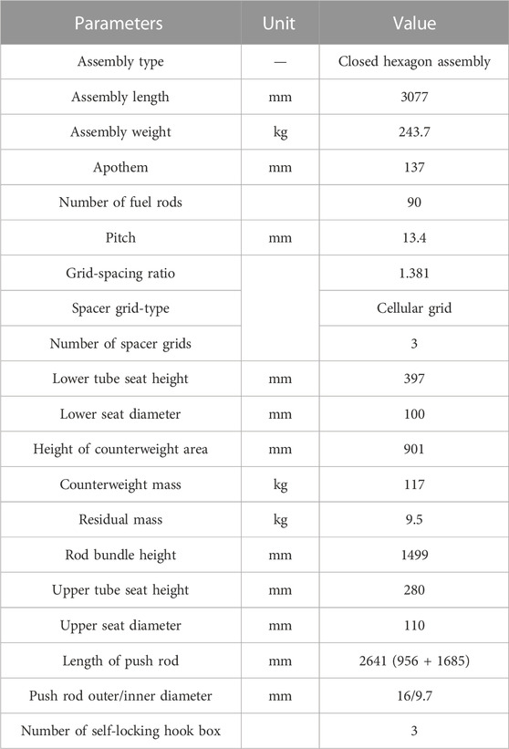
TABLE 7. Structural dimensions of the fuel assemblies.
The CiADS fuel assembly comprises 90 fuel rods and a control rod, with the fuel rods being held in place using grid-type spacers. The CiADS fuel assembly is divided into 186 sub-channels. The specific division and numbering of these sub-channels are illustrated in Figure 6, while the structural design of the CiADS fuel assembly’s grid-type spacers is shown in Figure 7. The grid-type spacers of the fuel assembly are constructed from 72 intermediate grid elements, 18 edge grid elements, and edge strips, all of which are welded together. Each grid element is designed to accommodate fuel rods. To secure the CiADS fuel assembly, three positioning grids are strategically placed at 1/4, 1/2, and 3/4 positions along the length of the fuel assembly.
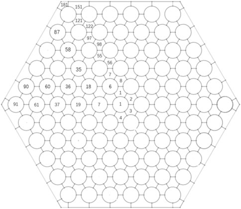
FIGURE 6. Sub-channel division and numbering of CiADS fuel assemblies.
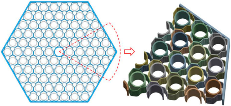
FIGURE 7. Structural design of CiADS fuel assembly grid-type spacers (Sheng, 2022).
To emphasize the contrast in coolant temperature between the inner and outer channels, this study chose seven sub-channel temperatures from various positions, ranging from the innermost to the outermost. As shown in Figure 8, in external channels, the corner channel exhibits a higher temperature than the side channel. This can be attributed to the side channel having a flow area three times larger than the corner channel, yet its overall heat transfer is just 1.5 times that of the corner. Furthermore, the fluid’s mass flow rate is greater in the side channel than in the corner channel. The calculation results indicate that the maximum coolant temperature occurs in sub-channel 8, reaching 660.16 K, which is lower than the maximum design temperature of 1823.15 K for the CiADS core coolant.
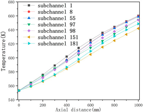
FIGURE 8. Calculated axial temperature distribution of the coolant in 7 different sub-channels in CiADS fuel assembly.
Figure 9 illustrates the distribution of cladding temperatures for different rods. The highest cladding temperature was recorded in rod 18, reaching 666.92 K, which remains below the CiADS design limit of 823.15 K. The temperature distribution of the cladding and the fuel center mirrors that of the coolant, with the fuel rods situated closer to the center exhibiting higher temperatures. Figure 10 displays the maximum fuel center temperature as 756.65 K, meeting the CiADS design requirement of 1523.15 K. The elevated cladding and fuel temperatures observed in rod 18, in comparison to other rods, can be attributed to its central position within the fuel assembly and the absence of heat sources from control rods. Positioned near the second ring of control rods, rod 18 experiences higher coolant temperatures in the surrounding sub-channels than other rod bundles. Consequently, this leads to relatively higher cladding and fuel temperatures calculated based on the coolant temperature.
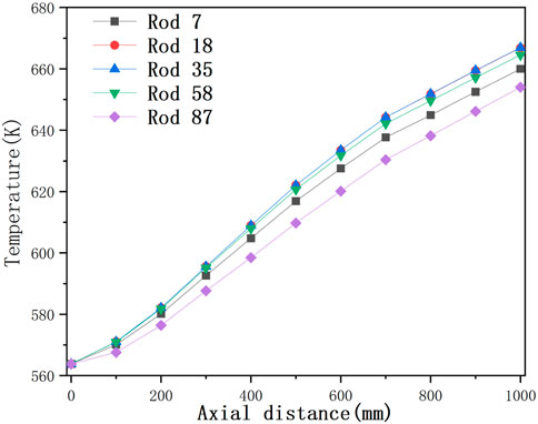
FIGURE 9. Temperature distribution of cladding at 5 different rods in CiADS fuel assembly.

FIGURE 10. Temperature distribution of fuel center at five different rods in CiADS fuel assembly.
Figure 11 presents the temperature profile of the hottest fuel rod among the 90 heated rods, depicting the coolant temperature, cladding temperature, and fuel center temperature. Owing to the cosine distribution of heat sources within the fuel rod, the thermal power density is heightened in the central section of the rod. Consequently, the calculated fuel rod temperatures, established on the thermal power density and coolant temperature, peak in the rear section of the central region before gradually declining.
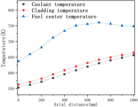
FIGURE 11. Temperature distribution inside the hottest rod (rod 18).
The mass flow rates of the inner channel, side channel, and corner channel are depicted in Figure 12. The results indicate a gradual increase in the mass flow rate of the inner channel, while the mass flow rates of the side channel and corner channel gradually decrease. As the coolant flows, the mass flow rate of the coolant within the grid-type spacers fuel assembly exhibits a trend of being higher in the central sub-channels and lower in the corner channels. This observation corroborates the conclusion that the temperature of the inner channel is higher than that of the side channel and corner sub-channel, as shown in Figure 8.
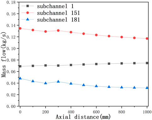
FIGURE 12. Axial distribution of mass flow rate in different sub-channels of CiADS fuel assembly.
In the context of the CFD method, smaller-sized rod bundle simulations are often employed instead of larger-sized ones, while maintaining calculation accuracy. Although certain calculation errors might arise due to the omission of certain conditions, substantial computational resources can be conserved. This approach is also adopted in sub-channel codes, wherein the rod bundle size is reduced for calculation while keeping the boundary conditions unchanged. In this study, calculations were performed for rod bundles consisting of 91 rods, 61 rods, 37 rods, 19 rods, and 7 rods, and the corresponding results are presented in Figures 13–15. The outcomes of the 61-rods and 37-rods cases closely resemble the simulation results obtained from calculations involving the full assembly of rods. To optimize computational efficiency, the simulation outcomes from the 37-rods case are recommended for use as a substitute for the simulation results of the full assembly. This approach enables significant computational resource savings without significantly compromising the reliability of the results.
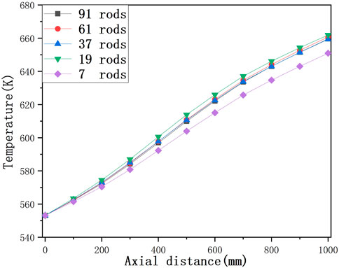
FIGURE 13. Central sub-channel (sub-channel 18) coolant temperature calculated with different rods.
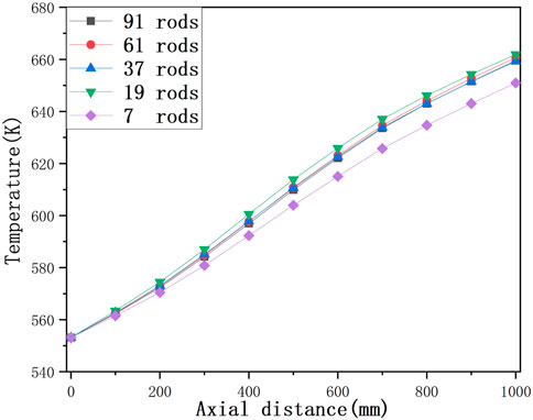
FIGURE 14. Side sub-channel coolant (sub-channel 151) temperature calculated with different rods.
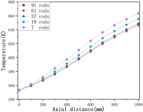
FIGURE 15. Corner sub-channel (sub-channel 181) coolant temperature calculated with different rods.
Building upon the sub-channel code developed by Liu et al. for thermal hydraulic analysis of LBE wound wire fuel assemblies, this study conducted a secondary development. A thermal hydraulic analysis code was developed specifically for fuel assemblies of LBE cooled fast reactors with grid-type spacers. A comparison was made between the results of the 19-rod flow heat transfer experiment carried out by Pacio and the calculations of coolant temperature to verify the code’s accuracy. Furthermore, an analysis was performed on the CiADS 91-rod fuel assembly using the sub-channel analysis code, based on design parameters. The analysis investigated the impact of coolant temperature, fuel rod temperature, coolant mass flow rate, and rod bundle arrangement. The findings can be summarized as follows:
Different models were evaluated for their applicability, and the Rehme, Petrunik, and Mikityuk models were recommended for calculating friction pressure drop, turbulent mixing, and convective heat transfer in CiADS sub-channel analysis.
The results from the code calculations closely aligned with the experimental data. As the Péclet number (Pe) increased, the temperatures of various sub-channels tended to approach the average temperature.
The code’s calculations indicated that the maximum coolant temperature occurred in sub-channel 8, while the maximum fuel rod temperature was in rod 18. Under steady operating conditions, the maximum fuel center temperature reached 756.65 K, and the maximum cladding temperature was 666.92 K.
By analyzing different rod numbers, it was determined that 37 rods were recommended as the minimum rod bundle configuration for simulating the full-scale fuel assembly.
The raw data supporting the conclusions of this article will be made available by the authors, without undue reservation.
Q-JC: Conceptualization, Data curation, Investigation, Methodology, Software, Validation, Writing–original draft, Writing–review and editing. JQ: Conceptualization, Investigation, Software, Writing–original draft, Writing–review and editing. J-BZ: Conceptualization, Investigation, Writing–original draft, Writing–review and editing. Y-FG: Conceptualization, Investigation, Methodology, Software, Writing–original draft, Writing–review and editing. X-KS: Conceptualization, Formal Analysis, Funding acquisition, Project administration, Software, Writing–original draft, Writing–review and editing. LG: Conceptualization, Funding acquisition, Project administration, Software, Writing–original draft, Writing–review and editing. J-TL: Investigation, Software, Writing–original draft, Writing–review and editing.
The author(s) declare financial support was received for the research, authorship, and/or publication of this article. This work is finally supported by the China Postdoctoral Science Foundation (2023M731458), the Gansu Natural Science Foundation (23JRRA1099), and the China Natural Science Foundation (12122512).
Author J-TL were employed by China Nuclear Power Engineering Co LTD.
The remaining authors declare that the research was conducted in the absence of any commercial or financial relationships that could be construed as a potential conflict of interest.
All claims expressed in this article are solely those of the authors and do not necessarily represent those of their affiliated organizations, or those of the publisher, the editors and the reviewers. Any product that may be evaluated in this article, or claim that may be made by its manufacturer, is not guaranteed or endorsed by the publisher.
Abderrahim, H. A., Baeten, P., De Bruyn, D., and Fernandez, R. (2012). MYRRHA–A multi-purpose fast spectrum research reactor. Energy Convers. Manag. 63, 4–10. doi:10.1016/j.enconman.2012.02.025
Abram, T., and Ion, S. J. E. P. (2008). Generation-IV nuclear power: A review of the state of the science. A Rev. state Sci. 36, 4323–4330. doi:10.1016/j.enpol.2008.09.059
Borishanskii, V. M., Gotovskii, M. A., and Firsova, E. V. (1969). Heat transfer to liquid metals in longitudinally wetted bundles of rods. Sov. At. Energy 27 (6), 1347–1350. doi:10.1007/bf01118660
Chen, , et al. (2012). Sub-channel model of Analysis cold fast ATHAS-LMR for LMFBR. Atomic Energy Sci. Technol. 46 (6), 695–700. doi:10.1115/ICONE26-81600
Cigarini, M., and Donne, M. D. (1988). Thermohydraulic optimization of homogeneous and heterogeneous advanced pressurized water reactors. Nucl. Technol. 80 (1), 107–132. doi:10.13182/nt88-a35553
Di Piazza, I., Angelucci, M., Marinari, R., Tarantino, M., and Forgione, N. (2016). Heat transfer on HLM cooled wire-spaced fuel pin bundle simulator in the NACIE-UP facility. Nucl. Eng. Des. 300, 256–267. doi:10.1016/j.nucengdes.2016.02.008
George, T., Basehore, K., Wheeler, C., et al. (1980). COBRA-WC: A version of COBRA for single-phase multiassembly thermal hydraulic transient analysis. Richland, WA, USA: Battelle Pacific Northwest Laboratories. Available at: http://refhub.elsevier.com/S0149-1970(18)30250-6/sref11.
Gräber, H., and Rieger, M. (1972). Experimentelle Untersuchung des Wärmeübergangs an Flüssigmetalle (NaK) in parallel durchströmten Rohrbündeln bei konstanter und exponentieller Wärmeflussdichteverteilung. Atomkernenerg. (ATKE) Bd 19, 23–40.
Gu, L., and Su, X. K. (2021). Latest research progress for LBE coolant reactor of China initiative accelerator driven system project. Front. Energy. 15 (4), 810–831. doi:10.1007/s11708-021-0760-1
Hager, W. H. (2003). Blasius: A life in research and education. Exp. Fluids 34 (5), 566–571. doi:10.1007/s00348-002-0582-9
Kazimi, M. S., and Carelli, M. D. (1976). Clinch River breeder reactor plant. Heat transfer correlation for analysis of CRBRP assemblies. Madison, PA United States: Westinghouse Electric Corp.
Kim, W. S., Kim, Y. G., and Kim, Y. J. (2002). A sub-channel analysis code MATRA-LMR for wire wrapped LMR subassembly. Ann. Nucl. Energy 29 (3), 303–321. doi:10.1016/s0306-4549(01)00041-x
Li, J. Y., He, Z. Y., Gu, L., Zhang, Y. P., Xu, H. S., Yao, C. F., et al. (2021). The temperature control of the dense granular spallation target in China initiative accelerator driven system based on quantum evolutionary algorithm. Prog. Nucl. Energ 131, 103587. doi:10.1016/j.pnucene.2020.103587
Li, S., Cao, L., Khan, M. S., and Chen, H. (2017). Development of a sub-channel thermal hydraulic analysis code and its application to lead cooled fast reactor. Appl. Therm. Eng. 117, 443–451. doi:10.1016/j.applthermaleng.2017.02.044
Liu, J. T., Peng, T. J., Wang, G., Su, X. K., Tao, Y. J., Fan, D. J., et al. (2022). Sub-channel analysis of lead–bismuth fast reactor fuel assembly with wire spacers for China initiative accelerator driven system. Ann. Nucl. Energy 170, 108965. doi:10.1016/j.anucene.2021.108965
Lodi, F., Grasso, G., Mattioli, D., and Sumini, M. (2016a). ANTEO+: A sub-channel code for thermal-hydraulic analysis of liquid metal cooled systems. Nucl. Eng. Des. 301, 128–152. doi:10.1016/j.nucengdes.2016.03.001
Lodi, F., Grasso, G., Mattioli, D., and Sumini, M. (2016b). ANTEO+: A sub-channel code for thermal-hydraulic analysis of liquid metal cooled systems. Nucl. Eng. Des. 301, 128–152. doi:10.1016/j.nucengdes.2016.03.001
Lyu, K., Chen, L., Yue, C., Gao, S., Zhou, T., and Huang, Q. (2016). Preliminary thermal-hydraulic sub-channel analysis of 61 wire-wrapped bundle cooled by lead bismuth eutectic. Ann. Nucl. Energy 92, 243–250. doi:10.1016/j.anucene.2016.01.034
Mikityuk, K. (2009). Heat transfer to liquid metal: review of data and correlations for tube bundles. Nucl. Eng. Des. 239 (4), 680–687. doi:10.1016/j.nucengdes.2008.12.014
Pacio, J., Daubner, M., Fellmoser, F., Litfin, K., Marocco, L., Stieglitz, R., et al. (2014). Heavy-liquid metal heat transfer experiment in a 19-rod bundle with grid spacers. Nucl. Eng. Des. 273, 33–46. doi:10.1016/j.nucengdes.2014.02.020
Peng, T. J., Gu, L., W, D. W., et al. (2017). Conceptual design of subcritical reactor for China initiative accelerator driven system. Atomic Energy Sci. Technol. 51 (12), 2235. doi:10.7538/yzk.2017.51.12.2235
Petrunik, K. J. (1968). Turbulent mixing measurements for single phase air, single phase water, and two-phase air-water flows in adjacent rectangular sub-channels. Windsor, ON, Canada: University of Windsor.
Rehme, K., and Trippe, G. (1980). Pressure drop and velocity distribution in rod bundles with spacer grids. Nucl. Eng. Des. 62 (1-3), 349–359. doi:10.1016/0029-5493(80)90038-2
Rehme, K. (1973). Pressure drop correlations for fuel element spacers. Nucl. Technol. 17 (1), 15–23. doi:10.13182/nt73-a31250
Rogers, J. T., and Tahir, A. E. E. (1975). Turbulent interchange mixing in rod bundles and the role of secondary flows. Pap. Am. Soc. Mech. Eng. 75.
Rowe, D. S., and Angle, C. W. (1967). Crossflow mixing between parallel flow channels during boiling. Part ii. Measurement of flow and enthalpy in two parallel channels. Richland, WA, USA: Pacific Northwest Lab. Available at: http://refhub.elsevier.com/S0029-5493(20)30020-0/h0100.
Rowe, D. S. (1970). COBRA-II: A digital computer program for thermal-hydraulic sub-channel analysis of rod bundle nuclear fuel elements. Richland, WA, USA: Battelle Pacific Northwest Laboratories. Available at: https://inis.iaea.org/collection/NCLCollectionStore/_Public/01/001/1001764.pdf.
Schroer, C., Wedemeyer, O., Skrypnik, A., Novotny, J., and Konys, J. (2012). Corrosion kinetics of steel T91 in flowing oxygen-containing lead–bismuth eutectic at 450 °C. J. Nucl. Mater. 431 (1-3), 105–112. doi:10.1016/j.jnucmat.2011.11.014
Seale, W. J. (1979). Turbulent diffusion of heat between connected flow passages Part 1: outline of problem and experimental investigation. Nucl. Eng. Des. 54 (2), 183–195. doi:10.1016/0029-5493(79)90166-3
Sheng, X. (2022). Research on structure and mechanical properties of fuel assembly for CiADS lead bismuth fast reactor. Guangdong, China: Institute of Modern Physics, Chinese Academy of Sciences. Available at: https://kns.cnki.net/kcms2/article/abstract?v=3uoqIhG8C447WN1SO36whLpCgh0R0Z-i16_wNaYct1rCckkTLVqOreKIRUCgs4uTvPKdTTxjIGezyHmuj_9ee6dlN2orMlJs&uniplatform=NZKPT.
Ushakov, P. A., Zhukov, A. V., and Matyukhin, N. M. (1978). Heat transfer to liquid metals in regular arrays of fuel elements. High. Temp.USSR Engl. Transl. U. S. 15 (5).
Wang, C., Wu, D., Gui, M., Cai, R., Zhu, D., Zhang, D., et al. (2021). Flow blockage analysis for fuel assembly in a lead-based fast reactor. Nucl. Eng. Technol. 53 (10), 3217–3228. doi:10.1016/j.net.2021.05.007
Wang, J., Tian, W., Tian, Y., Su, G., and Qiu, S. (2013a). A sub-channel analysis code for advanced lead bismuth fast reactor. Prog. Nucl. Energy 63, 34–48. doi:10.1016/j.pnucene.2012.09.010
Wang, J., Tian, W. X., Tian, Y. H., Su, G., and Qiu, S. (2013b). A sub-channel analysis code for advanced lead bismuth fast reactor. Prog. Nucl. Energy 63, 34–48. doi:10.1016/j.pnucene.2012.09.010
Wang, Z., Jia, D., and Yu., Z. (1983). Experiment investigation on the turbulent mixing between sub-channels for single-phase flow in a simulated bundle. Chin. J. Nucl. Sci. Eng. 3 (2), 106–114.
Wu, D., Wang, C., Gui, M., Lan, Z., Lu, Q., Zhang, D., et al. (2021). Improvement and validation of a sub-channel analysis code for a lead-cooled reactor with wire spacers. Int. J. Energy Res. 45 (8), 12029–12046. doi:10.1002/er.6015
Yu, R., Gu, L., Sheng, X., Li, J., Zhu, Y., Zhang, L., et al. (2021). Review of fuel assembly design in lead-based fast reactors and research progress in fuel assembly of China initiative accelerator driven system. Int. J. Energy Res. 45 (8), 11552–11563. doi:10.1002/er.6569
Keywords: CiADS, lead bismuth eutectic, grid spacers, sub-channel analysis, thermal-hydraulic
Citation: Chen Q-J, Qiu J, Zhang J-B, Guo Y-F, Su X-K, Gu L and Liu J-T (2023) Sub-channel analysis for LBE cooled fuel assembly with grid type spacers of China initiative accelerator driven system. Front. Energy Res. 11:1259254. doi: 10.3389/fenrg.2023.1259254
Received: 15 July 2023; Accepted: 05 September 2023;
Published: 22 September 2023.
Edited by:
Longxiang Zhu, Chongqing University, ChinaReviewed by:
Di Wang, China Nuclear Power Technology Research Institute, ChinaCopyright © 2023 Chen, Qiu, Zhang, Guo, Su, Gu and Liu. This is an open-access article distributed under the terms of the Creative Commons Attribution License (CC BY). The use, distribution or reproduction in other forums is permitted, provided the original author(s) and the copyright owner(s) are credited and that the original publication in this journal is cited, in accordance with accepted academic practice. No use, distribution or reproduction is permitted which does not comply with these terms.
*Correspondence: Xing-Kang Su, c3V4a0BsenUuZWR1LmNu
Disclaimer: All claims expressed in this article are solely those of the authors and do not necessarily represent those of their affiliated organizations, or those of the publisher, the editors and the reviewers. Any product that may be evaluated in this article or claim that may be made by its manufacturer is not guaranteed or endorsed by the publisher.
Research integrity at Frontiers
Learn more about the work of our research integrity team to safeguard the quality of each article we publish.