- College of Energy and Power Engineering, Lanzhou University of Technology, Lanzhou, Gansu Province, China
The oil–gas mixture pump significantly contributes to marginal oil field extraction and remote transportation of deep-sea oil. Nevertheless, during the operation of the mixture pump, it is inevitable to encounter problems like the separation of the mixed media from the hydraulic components as well as the gas phase from the liquid phase, which leads to enhancing the flow resistance of the mixed media. Therefore, this study investigates the influence of a groove-structure vortex generator on the drag reduction characteristics of a helical axial-flow gas–liquid multiphase pump under the design flow rate condition and various inlet gas content rates. The findings show that the vortex generator with diverse groove depths can prevent the separation of the mixed media from the blade suction surface effectively and minimize the flow resistance of the media in the 1/10 of the blade inlet. In particular, excellent drag reduction results were gained with a maximum drag reduction rate of 36.7% when the relative depth was 3/40. In addition, the efficiency of the mixture pump increased by a maximum of 2.1%, and the head increased by a maximum of 4.3%. The significance of this study lies in its potential to further optimize the design and performance of gas–liquid multiphase pumps. It provides new insights into the design and application of vortex generators. It offers robust support for the optimization and enhancement of gas–liquid multiphase pumps.
1 Introduction
It has become an unavoidable trend to exploit deep-sea natural resources due to the rapidly developing economy and human life. The helical axial-flow gas–liquid multiphase pump with a compact layout, lightweight feature, and small volume can more effectively transport multiphase fluids containing solid contaminants. The helical axial-flow oil–gas multiphase pump makes the gas–liquid two-phase fluid flow in the flow channel in a relatively complex way because of the complex structure, high-speed rotation, and large curvature, which generates the problems of gas–liquid separation, gas phase aggregation, and reduction of the flow channel area (OLSON, 2017; Ma et al., 2021; Zhao et al., 2022) such that the flow drag of the mixed media increases and the performance of the pump decreases. In this regard, the pump should be reasonably modified to improve its efficiency and ensure that it works appropriately under high gas content conveying conditions.
Since the mid-19th century, the basic principle of vortex generators to control turbulent boundary-layer separation was proposed in different forms (Smith, 1994). A vortex generator can reduce the degree of separation of the airflow near the wall of the blade, thereby reducing the energy loss in the process of fluid movement and improving the flow condition in the cascade channel. Chalia et al. increased the airfoil lift and reduced the flow resistance by arranging the groove-structured vortex generator on the airfoil surface (Chalia and Bharti, 2020). Hualing et al. explored the control mechanism of the vortex generator on the separation of bubbles on the suction side of the turbine blade by numerical analysis under the condition of Reynolds number Re = 5×10⁴. Their obtained results showed that the vortex generator delayed the separation, which helped to reduce the loss of fluid energy on the groove surface (Luo et al., 2009). Shen et al. arranged grooves in a pressurized water chamber of a centrifugal pump and found that the grooves reduced the flow resistance and improved the anti-cavitation performance of the pump (Shen and Chu, 2019).
According to the existing literature, the research findings of the vortex generator are applied to the multiphase pump blade modification design, and the external and internal characteristics of the changed multiphase pump are analyzed. Through our investigation, such findings hold significant implications for the optimization of the design and performance of gas–liquid two-phase flow pumps. In addition, appropriate selection and arrangement of concave grooved vortex generators can significantly enhance the flow characteristics of gas–liquid two-phase flow pumps, thereby improving their efficiency and performance. It provides a theoretical basis for reducing the resistance of the mixed media by suppressing the flow separation at the leading edge of the blade of a multiphase pump (Li et al., 2022; Yang et al., 2022; Li et al., 2023a; Li et al., 2023b).
2 Model design and mesh independence test
2.1 Design parameters
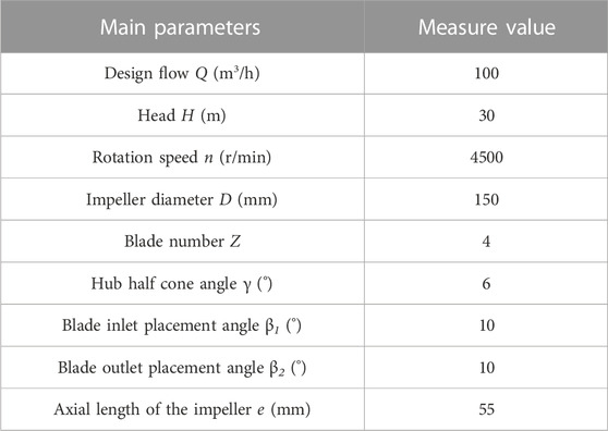
A complete compression unit of a helical axial-flow gas–liquid multiphase pump consists of an impeller and a guide blade. The primary focus of this study is on the mixing and transport characteristics of gas–liquid two-phase flow. So, the design flow rate Q refers to the overall flow rate of the gas–liquid two-phase flow. In order to make the two-phase flow more homogeneous and stable, the model of this paper incorporates a straight inlet section in front of the impeller and a straight outlet section at the rear end of the guide vane. The computational domain model of the multiphase pump is shown in Figure 1, and the parameter settings of the pump are shown in Table 1.
2.2 Determination of a groove-structured vortex generator
With the flow of mixed media through the suction surface, the pressure changes and forms an inverse pressure gradient, which leads to the backflow of the media, and finally, a dissipation vortex is formed. To obtain the breakaway and reconnection points of the two-phase mixed media during the conveying process, a dimensionless pressure coefficient Cp is defined as follows:
where P0 is the impeller inlet pressure, ρ is the density of the mixed media, and ν is the inlet velocity.
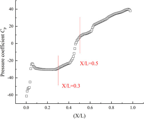
Figure 2 shows the pressure coefficient of the blade suction surface at 0.5 times the height of the blade under the conditions of design flow rate and import gas content IGVF = 40%. Since the inlet gas content does not affect the pressure distribution law on the suction side of the blade, this figure represents the design conditions of IGVF = 40%, with the pressure coefficient distribution pattern of the suction surface at 0.5 times the blade height position. The pressure coefficient gradually increases after the position of X/L = 0.3, which is regarded as the position where the bubbles flow back into the separation zone (Luo et al., 2009). Obviously, the position of X/L = 0.5, where the rate of change of the pressure coefficient decreases, is the reattachment point of the mixed media, which is consistent with the separation area obtained numerically.
The prominent role of the vortex generator is to effectively prevent the separation of the fluid and generation of the dissipative vortex and to reduce the loss of energy in the transport process of the fluid media. Therefore, a reasonable arrangement of the vortex generator is an effective measure to improve the performance of the gas–liquid multiphase pump.
Comparing the vortex generator with the boss structure (Jiang and Zhang, 2022), the groove structure is found to be more suitable for the multiphase pump. It not only has the same performance as the vortex generator in the boss structure but also can improve the flow area of the mixed media. Therefore, the groove-structured vortex generator is selected in this paper, the schematic diagram of which is shown in Figure 3. At present, V-shaped (Tang, 2020) and rectangular (Zhang et al., 2021) groove structures are more widely used. However, because of the high requirements for parallelism in the processing of V-shaped and rectangular grooves, the processing becomes more difficult and costly on the surface of a blade with a curved structure. Therefore, spherical processing is adopted in the present work.
Since 0.5 times of the chord length is the area where the separation of mixed media occurs, the groove-structured vortex generator is arranged at a distance of that length on the suction side. Considering that the conveying media of the mixture pumps are in gas and liquid phases and the inlet gas content IGVF = 20%–60%, the arrangement area on the periphery is expanded accordingly. From the calculation, it is found that the diameter of the groove should be a manageable size. According to Table 2, groove depths of 0.1, 0.2, 0.3, 0.4, and 0.5 were selected (with a groove depth of 0.5 serving as the control group, where the relative depth exceeds 1/10). This is because the relative depth of an individual vortex generator should be less than 1/10. Therefore, based on the relative depths of the grooves, the maximum value of D was chosen as 4 mm. Therefore, the relationship between the groove diameter D, groove depth δ, chord length, and blade thickness are determined as D = 0.02L and 0.014d ≤ δ ≤ 0.071d. The parameters of the proposed structure of the vortex generator are listed in Table 2.
2.3 Mesh independence verification
In this study, we consider the boundary-layer mesh. In order to ensure that the first-layer mesh height near the wall meets the chosen value of y+ when using the SST k-ω model at a high Reynolds number, we need to solve the equation based on the relationship between the first-layer mesh height y and the dimensionless parameter y+. The solution process is as follows: first, the first-layer height y is given, the mixing pump mesh is divided, and then, the boundary-layer flow simulation is performed. Through repeated iterations, it is finally determined that the height of the first layer of the grid y = 0.01 mm meets y+ ≈ 1, which is in line with the calculation conditions.
where μ represents the dynamic viscosity of the composite medium, kg/(m·s); ρ denotes the density of the composite medium, kg/m³; uτ represents the wall shear velocity, m/s; and τω represents the shear stress between the composite medium and the wall surface, Pa.
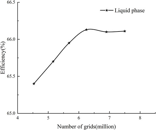
The computational domain of Figure 1 was meshed using the meshing software ICEM. It is known that the higher the grid number, the more accurate the result is. However, due to the limited computing resources, the model of the computational domain is checked for grid independence under the design flow and pure liquid phase conditions. As shown in Figure 4, the considered final number of grids was 6.25 million.
In Figure 5, (A) is the boundary-layer grid detail diagram, (B) is the mesh of the impeller fluid computational domain, and (C) is the local mesh detail.

FIGURE 5. (A) Boundary-layer grid detail diagram. (B) Grid of the computational domain for impeller fluid flow. (C) Local grid detail diagram.
2.4 Validation of the numerical method
In this paper, by using the gas–liquid two-phase flow experimental bench, around the design flow rate Q = 100 m3/h, five different flow rates (0.6Q, 0.8Q, 1.0Q, 1.2Q, and 1.4Q) are selected, and the external characterization experiments are performed under the condition of inlet gas content ratio IGVF = 40%. The experimental outcomes and numerical simulation results are compared to examine the validity of the numerical approach. A comparison of the two, as shown in Figure 6, reveals that the head error and efficiency error are within 10%, within a reasonable range, indicating that the numerical calculation method chosen is reliable and accurate.
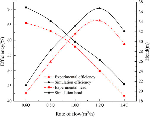
FIGURE 6. Comparison of the external characteristics of the numerical simulation and the experimental multiphase pump.
3 Flow control equations and boundary conditions
3.1 Flow control equations
The Euler model, known as the two-fluid model, treats the constituents as continuous media. To accurately characterize the interphase force in gas–liquid two-phase flows, we employed the widely utilized Schiller–Naumann model (Schiller and Naumann, 1933) as the drag force model in our two-phase calculations. The Euler model assumes that each component has a separate flow field, with separate velocities and other physical fields. The advantage of the model is that it allows for more complete, total, and accurate flow calculations.
The continuity equation for the Eulerian model takes place as follows (Wang, 2004):
The momentum equation for the Eulerian model is as follows (Wang, 2004):
where l represents the liquid phase and g represents the gas phase; αl and αg are the volume fractions of the two phases, respectively; ρl and ρg are the densities of the two phases, respectively; Ul and Ug are the flow velocities of the two phases, respectively; p is the pressure; fl and fg are the masses of the two phases, respectively; and Ml and Mg are the surface tensions of the two phases, respectively (Wang, 2004).
3.2 Boundary conditions
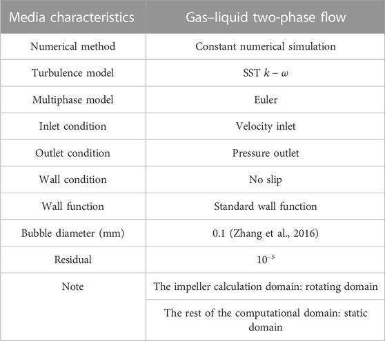
Numerical simulation of the flow field of a multiphase pump is performed in a three-dimensional mode based on Ansys Fluent software, which discretizes the constant characteristics of the flow field in the impeller channel by the Navier–Stokes equations. The boundary conditions are shown in Table 3.
4 Analysis of results
4.1 Analysis of the groove-structured vortex generator
Vorticity is a kinematic physical quantity that describes the rotation of a fluid and is vectorial. The strength of vortices inside a flow channel is directly proportional to the energy dissipation (Wu, 1986; Zhang, 2019). Figure 7 shows the clouds of vortex systems in the region of the groove on the suction surface of the blade for both the original model and the different schemes at Q = 100 m3/h and IGVF = 40%. The Q-criterion level = 0.01 is selected to process the area where the vortex generators are arranged and color the liquid phase velocity of the vortex system. It can be seen from Figure 7 (A) that the vortex system formed on the suction side gradually extends along the flow direction, which is similar to the change in the state of flow of mixed media. It shows that the vortex system is formed due to the mixed media separating from the wall during transportation. It also shows that the vortex generators can be arranged to suppress the separation. Moreover, when the relative depth is less than 1/10, it can not only suppress the separation of the mixed media and suction side but also reduce the near-wall velocity of the mixed media in the area of the vortex generator and its rear side. It further decreases the mixed media’s shear stress on the wall, reducing energy consumption during the conveying process.
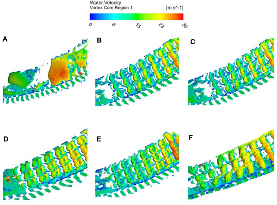
FIGURE 7. Vortex cloud diagrams of different schemes: (A) original model, (B)
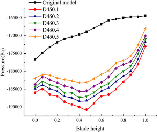
Since the pressure gradient is closely related to the vorticity intensity, there is an enormous pressure gradient in the range of X/L = 0.3 to X/L = 0.5 along the flow direction, and a vortex system of a similar size appears in this area. So, the vorticity intensity of the vortex system can be reduced by controlling the pressure gradient. Figure 8 shows the pressure change in the original model with diverse schemes in the same area under the design flow condition and inlet gas content IGVF = 40%. The pressure gradient at this location can be seen in the figure, where the vortex generator is arranged, which is more significant than that in the original model, indicating that the vortex system appears only on the surface of the vortex generator after it is arranged. The greater the relative depth, the greater the pressure gradient in the vortex generator area, and the vortex distribution on the surface is noticeable. The specific fitting function is expressed as follows:
where Sp is a multiple of the blade height, δ is the groove depth, and P is the pressure; a = 31530.76; b = 14418.75; c = 21841.2; and d = 1.87×10⁵.
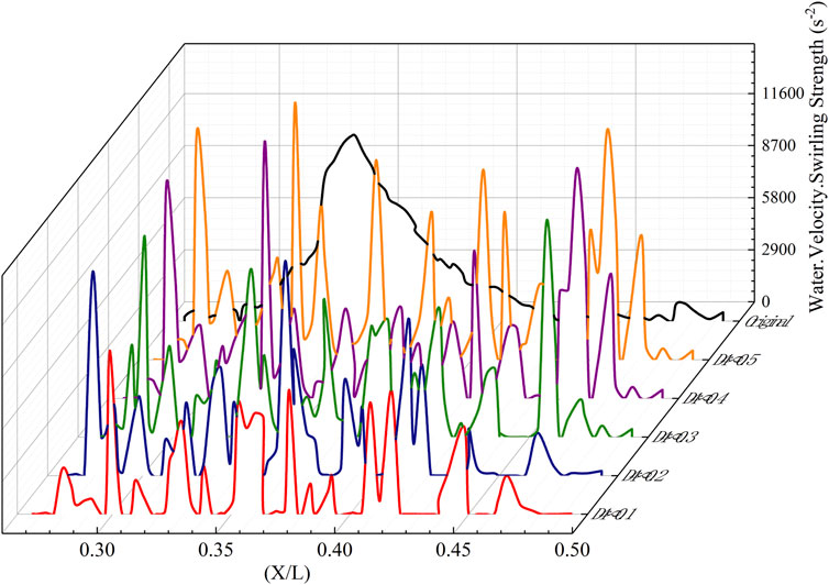
Figure 9 shows the vorticity intensity curves in the original model for different schemes in the area where the vortex generators are arranged under the design flow condition and IGVF = 40%. It is seen from the distribution of the vorticity intensity that the original model has an immense vorticity intensity at the chord length position X/L = 0.35. The distributions of the vorticity intensities of different groove structures in the same area differ. However, the distribution of the vorticity intensity of each scheme shows multiple peaks, and each peak corresponds to a vortex generator. For the extreme vorticity intensity, some extreme values of D4δ0.4 and D4δ0.5 exceed those in the original model, resulting in the loss of kinetic energy of the mixed media and a reduction in the performance of the multiphase pump.
4.2 Analysis of friction stress
Gas–liquid mixtures are high-Reynolds number fluids, and the magnitude of the Reynolds stress depends on the turbulence intensity and the properties of the vortex structure. Fluid viscosity causes tangential drag when relative slip occurs between fluid particle models, and viscous drag develops when the fluid undergoes internal friction on the walls it contacts (Wu et al., 2014; Gu et al., 2015; Li, 2018). It is expressed as follows:
where Ai is the wall discrete unit area and τi is the wall discrete unit shear stress.
The wall shear stresses are composed of viscous shear stresses and turbulent Reynolds stresses. It is expressed as follows:
where vx and
Multiphase pump conveying mixed media for gas–liquid two-phase flow: In considering the shear stress, it is necessary to consider the shear stresses of both phases. This paper focuses only on the blade suction surface X/L = 0.3–0.5 region as the object of investigation.
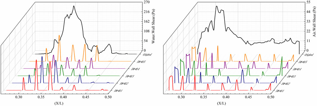
The velocity in the main flow channel of the impeller is large, and that in the groove is small, resulting in a dividing line between the two flow fields. Under Q = 100 m3/h and IGVF = 40%, the shear stress in the original model and those under different schemes of the suction side are shown in Figure 10, where it can be seen that the shear stress on the liquid and gas phase relative to the suction side of different schemes is smaller than that in the original model. The shear stress of D4δ0.3 is the smallest, and that of D4δ0.1 and D4δ0.5 is more extensive. Since the relative depth of the D4δ0.1 groove structure is too small, failure occurs in suppressing the separation of mixed media from the suction surface. The relative depth of the D4δ0.5 groove structure is more remarkable than 1/10, which affects the flow state of the mixed media near the wall and increases its shear stress on the suction side.
The Reynolds stress is also known as turbulent stress. The Reynolds stress is generated due to the pulsation of fluid flow rate and multiphase and collision of micelles inside the fluid. Therefore, the Reynolds stress on the suction surface of the blade is directly represented by the turbulent kinetic energy. Figure 11 shows the variation of the turbulent kinetic energy of the original model and at different scenarios for the condition of design flow and IGVF = 40%. The figure shows that the turbulent kinetic energies of D4δ0.1, D4δ0.2, and D4δ0.3 are smaller and those of D4δ0.4 and D4δ0.5 are larger than those in the original model. The turbulent kinetic energy on the suction side of the grooved blade shows continuous periodicity, and each cycle corresponds to a vortex generator. Observing a cycle under different schemes, it can be found that the relative depth of the groove-structured vortex generator has a significant influence on the turbulent kinetic energy. The greater the relative depth of the groove structure, the greater the turbulent kinetic energy. When the relative depth of the groove structure is less than 1/10, it is possible to effectively inhibit mixed media and the suction surface of separation, which reduces near-wall turbulent kinetic energy and decreases the loss of energy of the mixed media in the conveyance process.
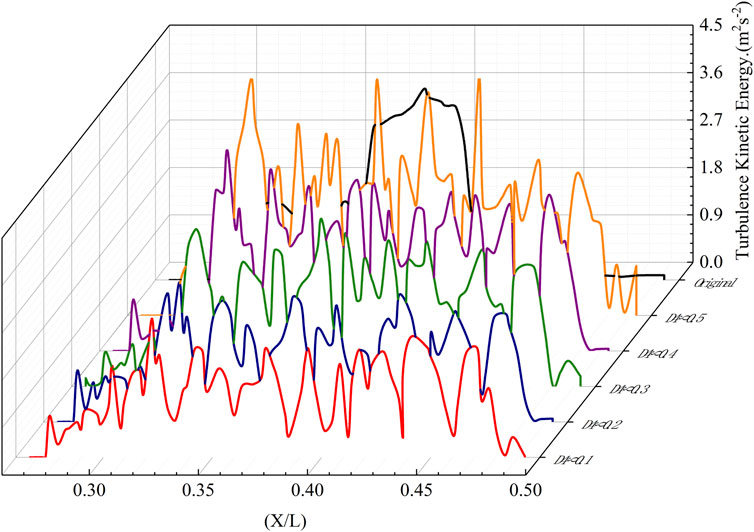
FIGURE 11. Distribution of turbulent kinetic energy distribution in the original model under different schemes.
The groove-structured vortex generator is arranged in the region of the blade suction surface to analyze the shear stress and turbulent kinetic energy data in the suction surface of the blade. The data within this region were subjected to averaging procedures, and the results are presented in Tables 4–6. These tables provide values for the averaged shear stress and averaged turbulence kinetic energy. With the aid of this data, we can gain a deeper understanding of the flow characteristics occurring within the suction surface region of the blades.
During the operation of the mixture pump, the transported gas–liquid flow through the blade suction surface will cause the boundary-layer separation phenomenon. At this time, the shear stress and turbulent kinetic energy of the wall surface in the separation zone will increase, and the motion resistance of the gas–liquid two-phase in the separation zone will also increase. The groove-structured vortex generator is arranged in the area of the boundary-layer separation phenomenon to change the pressure difference between the suction surface of the blade to reduce the separation phenomenon so that the media are better attached to the wall. From Table 4, Table 5, and Table 6, it can be seen that the resistance increases when the relative depth of the groove structure δ/D ≥ 1/10 and decreases when the relative depth of the groove structure δ/D < 1/10. However, the relative depth of the groove structure is too small, which will make the vortex generator lose its function. When Q = 100 m3/h and IGVF = 40%, in the area where the vortex generator is arranged on the blade suction surface, the shear stress of the liquid phase on the wall is reduced by 27% at most, the shear stress of the gas phase on the wall is reduced by 29.4% at most, and the turbulence kinetic energy is reduced by 19.6% at most.
4.3 Analysis of the resistance characteristic
The wall drag reduction rate in gas–liquid two-phase flow:
where F is the viscous resistance on the wall before modification and Fg is that after modification.
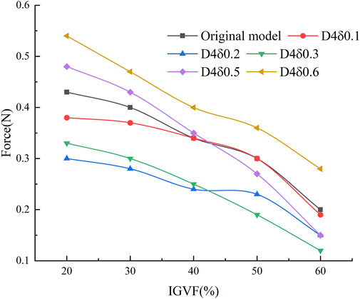
The mixed media resistance curves for different models in the region of vortex generator arrangement on the suction surface of the blade under the design condition and varying inlet gas content are shown in Figure 12. As shown in the figure, the resistance is increased when the relative depth δ/D of the groove structure is greater than 1/10. The drag reduction effect is not good when δ/D < 1/40, and it is apparent only when 1/40< δ/D < 1/10. According to the drag reduction rate, D4δ0.3 has the best drag reduction effect, and the maximum drag reduction rate is 36.7% when IGVF = 50%. The mixed media resistance tends to decrease as the inlet gas content increases. The specific fitting function is expressed as follows:
where Vgas is the inlet gas content, δ is the groove depth, and F is the resistance of the mixed media; a = −0.1511; b = 0.0518; c = 0.0702; d = 0.1219; e = 0.0469; f = 0.1664; and g = 0.3276.
4.4 Influence of the groove-structured vortex generator on the external characteristics of the multiphase pump
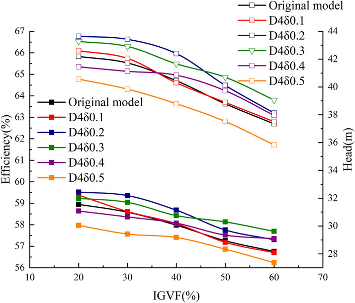
With the original model and various schemes, the efficiency-head curves are shown in Figure 13 for the design flow condition and various inlet gas content conditions. The horizontal axis represents the inlet gas content IGVF (%) of the multiphase pump. The curve marked with a hollow square on the left axis represents the efficiency (%) of the multiphase pump, and that marked with the solid square on the right axis represents the head H (m). Observing the efficiency-head curve of the original model, it is known that with the increase in inlet gas content, both the efficiency and head of the multiphase pump show a tendency to decline. Each scheme shows the same trend of the original model of the efficiency and head, indicating that the main reason for the reduction of the external characteristics of the multiphase pump is the increase in the gas content of the inlet. The maximum increment in both efficiency and head of the multiphase pump occurs in D4δ0.3. The best drag reduction is achieved at the inlet gas content IGVF = 50%, and the increase in the efficiency and head is 2.1% and 4.3%, respectively.
Observing the external characteristics of the multiphase pump in different schemes, it can be seen that under different inlet gas contents, the maximum increase in the efficiency and head of the pump appears in different schemes. Taking the efficiency curve as an example, when the inlet gas content is between 30% and 40% and the relative depth δ/D is 1/20, the increase in the efficiency is the largest. When the inlet gas content is between 50% and 60% and the relative depth δ/D is 3/40, the increase in efficiency is the largest. The distribution of the maximum increment in the head of the multiphase pump is similar, indicating that the drag reduction effect of the vortex generator has a specific relationship with the inlet gas content of the pump. However, when the relative depth δ/D > 1/8, both efficiency and head decrease, which means that when the relative depth is too large, it will disturb the main flow in the impeller channel. It shows that when the relative depth of the groove structure is too large, the main flow in the impeller channel will be disturbed, resulting in an increase in the resistance and a decrease in the head and efficiency of the multiphase pump. Between the multiphase pump inlet gas content with efficiency and head to fit, which can be seen in a quadratic function of the relationship between them, the specific function of the fitting is shown in Eq. 13. With the increase in inlet gas content, the efficiency and head of the multiphase pump presented a downward trend.
where Vgas is the inlet gas content, δ is the groove depth, and η and H are the efficiency and head of the multiphase pump, respectively; a = −0.5984; b = 0.874; c = −3.1; d = 90.19; e = −2.05; f = 0.4248; g = −3.07; and h = 67.9.
5 Conclusion
This paper analyzes in detail the increase in flow resistance caused by the separation of the mixed media from the suction surface when it flows through the arch bridge-shaped suction surface during pump operation. A scheme is proposed for arranging groove-structured vortex generators with different relative depths on the suction side of the blade. The numerical calculation of each scheme is carried out in the Ansys Fluent solver under the conditions of Q = 100 m3/h and IGVF = 20–60%; the data obtained from the calculations are compared with the initial scheme to summarize the law of influence of the vortex generator on the characteristics of the multiphase pump. This study did not consider non-steady-state conditions and varying groove shapes, which can significantly impact the performance and optimization of gas–liquid mixing. Future research should explore these factors for performance enhancement and design optimization.
1) Arranging the groove-structured vortex generator in the separation area, the pressure difference between the pressure side and suction side of the blade can be increased. An increase in the relative depth of the groove structure changes the pressure gap between the suction surfaces of the blades, reducing the separation phenomenon and allowing the media to adhere better to the surface of the wall. The flow resistance of the mixed media increases when the relative depth of the groove structure δ/D ≥ 1/10. When 1/40 < δ/D < 1/10, the drag reduction effect is obvious, and the maximum drag reduction rate in the region of X/L = 0.3–0.5 is 36.7%.
2) When the inlet gas content changes, the results of the groove-structured vortex generator schemes with different relative depths are different. Under the design flow condition and inlet gas content IGVF = 40%, in the suction surface in the area of the vortex generator arrangement, the shear stress of the liquid phase on the wall is reduced by a maximum of 27%, the gas phase on the wall is reduced by a maximum of 29.4%, and the turbulent kinetic energy is reduced by a maximum of 19.6%. When the relative depth δ/D = 3/40, the drag reduction effect is the best in the area of X/L = 0.3–0.5 under the design flow condition. When the IGVF = 50%, the best resistance reduction effect is in the region of X/L = 0.3–0.5, the maximum increment of efficiency is 2.1%, and the maximum head is 4.3%.
Data availability statement
The original contributions presented in the study are included in the article/Supplementary Material; further inquiries can be directed to the corresponding authors.
Author contributions
YX: data curation, writing–original draft, and writing–review and editing. WH: writing–review and editing. ZJ: writing–review and editing. MX: writing–review and editing. LY: validation and writing–review and editing. JZ: writing–review and editing. ZG: writing–review and editing. SY: writing–review and editing.
Funding
The authors declare financial support was received for the research, authorship, and review of this article. This study was supported by research on the coupling mechanism of cavitation and wear and progressive damage characteristics of hydraulic machinery, the National Natural Science Foundation of China (No. 52179086), and dynamic instability of air-stagnation of spiral axial gas–liquid mixing pump and its adaptive control strategy, the National Natural Science Foundation of China (No. 52269022).
Conflict of interest
The authors declare that the research was conducted in the absence of any commercial or financial relationships that could be construed as a potential conflict of interest.
Publisher’s note
All claims expressed in this article are solely those of the authors and do not necessarily represent those of their affiliated organizations, or those of the publisher, the editors, and the reviewers. Any product that may be evaluated in this article, or claim that may be made by its manufacturer, is not guaranteed or endorsed by the publisher.
References
Chalia, S., and Bharti, M. K. (2020). Design and analysis of vortex generator and dimple over an airfoil surface to improve aircraft performance. Int. J. Adv. Eng. Res. Appl. (IJA-ERA 3.
Gu, Y., Mu, J., and Dai, D. (2015). Drag reduction characteristics on gas-liquid two-phase flow based on gas jet. Propuls. Technol. 36 (11), 1640–1647.
Jiang, S., and Zhang, S. (2022). Study on flow characteristics of turbulent wakes in hemispheric array eddy current generator. Mach. Des. Manuf. 376 (6), 193–198.
Li, K. J. (2018). Study on drag reduction capability of BionicDimple impeller and dynamic characteristics of centrifugal pump. master’s thesis. Harbin, China: Harbin Engineering University.
Li, W., Li, Z., Han, W., Li, Y., Yan, S., Zhao, Q., et al. (2023a). Measured viscosity characteristics of Fe3O4 ferrofluid in magnetic and thermal fields. Phys. Fluids 35 (5). doi:10.1063/5.0131551
Li, W., Li, Z., Han, W., Li, Y., Yan, S., Zhao, Q., et al. (2023b). Relationship between 25-hydroxyvitamin D and IGF1: A cross-sectional study of the third national health and nutrition examination survey participants. Phys. Fluids 35 (1), 35. doi:10.1186/s41043-023-00374-6
Li, W., Li, Z., Qin, Z., Yan, S., Wang, Z., and Peng, S. (2022). Influence of the solution pH on the design of a hydro-mechanical magneto-hydraulic sealing device. Eng. Fail. Anal. 135, 106091. doi:10.1016/j.engfailanal.2022.106091
Luo, H. L., Qiao, W. Y., and Xu, K. F. (2009). Passive control of laminar separation bubble with spanwise groove on a low-speed highly loaded low-pressure turbine blade. J. Therm. Sci. 18 (3), 193–201. doi:10.1007/s11630-009-0193-0
Ma, X., Han, Z., Wang, H., Weng, Y., Cao, X., Liu, F., et al. (2021). Identification and characterization of regulatory pathways involved in early flowering in the new leaves of alfalfa (Medicago sativa L.) by transcriptome analysis. Fluid Mach. 49 (10), 8. doi:10.1186/s12870-020-02775-9
Schiller, L., and Naumann, Z. (1933). Uber die grundlegenden Berechnungen bei der Schwerkraftaufbereitung. Z. Des. Vereines Dtsch. Ingenieure 77, 318–320.
Shen, Z., and Chu, W. (2019). Influence of grooves arrangement in volute casing on internal flow characteristics of centrifugal pump. Univ Sci Tech Nat. Sci. Ed. 47 (12), 37–42. doi:10.13245/j.hust.191207
Smith, F. T. (1994). Theoretical prediction and design for vortex generators in turbulent boundary layers. Fluid Mech. 270, 91–132. doi:10.1017/s0022112094004210
Tang, R. S. (2020). V-Groove rectangular microchannel flow and heat transfer characteristics of study. master’s thesis. Qingdao, China: Qingdao University of Science and Technology.
Wang, F. J. (2004). Computational fluid dynamics analysis. Beijing, China: Tsinghua University Press.
Wu, J. (1986). Acta aerodyn. sin. https://apps.dtic.mil/sti/citations/ADA174599.
Wu, Z., Hao, X., and Rong, R. (2014). Study on drag-reduction mechanism of riblet surface on aerofoil blade of centrifugal fan. J. Syst. Simul. 26 (6), 1355–1361. doi:10.16182/j.cnki.joss.2014.06.006
Yang, P., Chen, S., Li, W., and Zeng, C. (2022). Large-eddy simulation of the boundary layer development in a low-pressure turbine cascade with passive flow control. Front. Energy Res. 10, 853166. doi:10.3389/fenrg.2022.853166
Zhang, J., Cai, S., Li, Y., Zhu, H., and Zhang, Y. (2016). Visualization study of gas-liquid two-phase flow patterns inside a three-stage rotodynamic multiphase pump. Exp. Therm. Fluid Sci. 70, 125–138. doi:10.1016/j.expthermflusci.2015.08.013
Zhang, K., Ye, J., and Zhang, Y. (2021). Study on the tip vortex control effect and rule of pump jet thruster by groove structure. J. Ship Mech. 25 (12), 1594–1605.
Zhang, X. (2019). Model test on vertical axial flow pump device andInternal flow characteristic analysis on inlet conduit and outlet conduit. master’s thesis. Zhenjiang, China: Jiangsu University.
Keywords: helical axial-flow pump, gas-liquid two-phase, groove-structured vortex generator, flow separation, drag reduction
Citation: Han W, Yang X, Zhang J, Xiao M, Yan L, Zhou J, Gu Z and Yang S (2023) Influence of a groove-structured vortex generator on the drag reduction characteristics of a multiphase pump. Front. Energy Res. 11:1257170. doi: 10.3389/fenrg.2023.1257170
Received: 12 July 2023; Accepted: 13 September 2023;
Published: 29 September 2023.
Edited by:
Enhua Wang, Beijing Institute of Technology, ChinaReviewed by:
Ling Zhou, Jiangsu University, ChinaShengnan Yan, Xihua University, China
Fangyang Yuan, Jiangnan University, China
Copyright © 2023 Han, Yang, Zhang, Xiao, Yan, Zhou, Gu and Yang. This is an open-access article distributed under the terms of the Creative Commons Attribution License (CC BY). The use, distribution or reproduction in other forums is permitted, provided the original author(s) and the copyright owner(s) are credited and that the original publication in this journal is cited, in accordance with accepted academic practice. No use, distribution or reproduction is permitted which does not comply with these terms.
*Correspondence: Wei Han, aGFud2VpQGx1dC5lZHUuY24=; Xiang Yang, MjEyMDgwNzA0MDMwQGx1dC5lZHUuY24=
 Wei Han
 Xiang Yang
 Jing Zhang
