 Xiaoliang Yang1,2*
 Rui Wang
95% of researchers rate our articles as excellent or good
Learn more about the work of our research integrity team to safeguard the quality of each article we publish.
Find out more
ORIGINAL RESEARCH article
Front. Energy Res. , 04 September 2023
Sec. Sustainable Energy Systems
Volume 11 - 2023 | https://doi.org/10.3389/fenrg.2023.1236646
The Virtual Synchronous Generator (VSG) emulates the characteristics of a synchronous generator to provide inertia and damping for renewable energy systems. In the case of using the NPC three-level converter structure, traditional control methods require complex dual-loop control and internal PI parameter tuning. Furthermore, although fixed-parameter VSG control can provide inertia and damping when a significant power load is switched in an islanded microgrid, it cannot guarantee frequency regulation performance. To address these issues, this paper proposes an NPC three-level VSG parameter adaptive finite control set model predictive control strategy. This method eliminates the need for dual-loop control and PI parameter tuning. By incorporating angular velocity deviation and its rate of change into adaptive adjustment, a Tracking-Differentiator (TD) is designed to calculate the rate of change of angular velocity. This approach avoids frequent fluctuation of adaptive parameters during load power switching and improves the frequency stability of the microgrid. The effectiveness of the proposed strategy is validated through simulation and experimental verification.
To address the global energy crisis, a new wave of energy transformation is flourishing, with solar energy and wind energy leading the way. Correspondingly, distributed generation technologies and microgrid technologies have also experienced rapid development (Xu et al., 2017; Li et al., 2019; Pournazarian et al., 2021).
Currently, distributed generation is mainly connected through power electronic devices. However, power electronic devices have characteristics such as fast response, low inertia, and no damping (Jiang et al., 2017; Zhou et al., 2019; Koiwa et al., 2021). When a microgrid experiences sudden changes or disturbances in load power, the system cannot provide a certain frequency and voltage support, which adversely affects system stability. To address this issue, some scholars have studied the Virtual Synchronous Generator (VSG) technology (Beck et al., 2007; Ding et al., 2009; Zhong et al., 2010). The objective of the VSG strategy is to emulate the behavior of traditional synchronous generators, enabling distributed energy systems to operate in a manner similar to conventional power systems. This emulation is achieved by controlling the inverters present in the distributed energy system, which convert the DC from renewable energy sources into AC and supply it to the demand side. This technology improves the operational stability of weak grids (Li et al., 2016).
The Neutral Point Clamped (NPC) three-level inverter, compared to the two-level inverter, offers several advantages such as higher equivalent switching frequency, multiple voltage vectors, lower voltage stress on individual switches, and higher quality of output power with reduced harmonics. As a result, it has become a research hotspot in the field of power electronics and power transmission technology today (Jung et al., 2019; Jun et al., 2020; Zorig et al., 2022). Common control methods for NPC three-level inverters include pulse width modulation (PWM) (Ye et al., 2015) and space vector modulation (SVM) (Sebaaly et al., 2016). These methods generate the corresponding modulated signal by measuring the voltage and current feedback signal and comparing it with a given reference signal. However, this process typically requires the adoption of Proportional-Integral (PI) control, and the tuning of modulation parameters can be quite complex. The Finite Control Set Model Predictive Control (FCS-MPC) algorithm, on the other hand, offers advantages such as robustness, simplicity of control, no need for PWM modulation, and the ability to perform multi-objective control. Due to these advantages, it has been applied in the field of nonlinear control (Aguirre et al., 2020; Guo et al., 2022; Jin et al., 2022; Yan et al., 2022) applied model predictive control to a three-level NPC grid-connected inverter and proposed a virtual vector-based control strategy for the NPC inverter without considering the NPV weighting factor. This strategy simplifies the vector selection process and achieves excellent control performance (Jin et al., 2022). Proposed a VSG grid-connected model predictive control method by integrating MPC with VSG. This method provides both inertia and damping characteristics to the grid while also offering support for both active and reactive power. However, all the mentioned references focus on control strategies under grid-connected conditions. In comparison to interconnected power systems, islanded systems have poor static and dynamic stability due to limited frequency control means. In regions with severe active power deficits, frequency collapse can occur, posing a significant threat to the safe operation of the system. The research on model predictive control for islanded load power switching in VSG models is currently not extensively explored.
The virtual inertia and damping are core control parameters of VSG, and adjusting these parameters appropriately can effectively enhance the control performance of VSG (Li et al., 2019; Li and Jia, 2019). In islanded microgrids, the frequency is primarily determined by the balance between generation and load. Therefore, it is crucial to optimize the frequency support mechanisms to ensure stable operation despite the variable nature of renewable energy generation. While a fixed-parameter VSG can provide some inertia and damping to the system when the load in an islanded microgrid changes, its frequency regulation capability and control flexibility are limited (Chen et al., 2016). proposed a VSG transient response optimization control method based on parameter adaptive adjustment. It minimizes transient response time, with the limitation of frequency amplitude and change rate being constraints and the system’s new equilibrium point being the boundary condition. The fluctuation of VSG frequency and power in the transient process is effectively suppressed (Shi et al., 2021). Proposed an improved adaptive virtual synchronous generator control strategy, which incorporated frequency deviation and frequency change rate into VSG virtual parameters. It adaptively adjusts the virtual inertia and damping parameters of the VSG system to improve frequency stability during power transients in the microgrid. However, these adaptive parameter tuning strategies require the implementation of segment functions to constrain virtual inertia and damping coefficients, aiming to reduce parameter fluctuations. This might result in parameter discontinuities and a complex parameter calculation process. Additionally, they do not consider the problem of significant parameter changes resulting from unstable angular velocity during load variations. The introduction of frequently fluctuating parameters into VSG control is not conducive to the stability of the system frequency.
In summary, this paper derives the mathematical model of NPC three-level VSG-MPC based on model predictive control theory, and proposes an improved parameter adaptive VSG model predictive control strategy. In addition, a TD is designed to accurately calculate the rate of change of angular velocity dω/dt by considering in the adaptive parameter adjustment strategy. The main work of this article can be summarized as follows:
1) This method adopts a simplified VSG structure, using the output voltage of VSG virtual impedance as the reference value, without using the complex dual loop control and PI parameter debugging in traditional methods. This approach allows the NPC three-level inverter to exhibit characteristics similar to a synchronous generator.
2) This article investigates the mechanism of the impact of virtual inertia and damping on the frequency of microgrids when the load power changes. An improved VSG parameter adaptive adjustment strategy has been designed. Introducing angular velocity deviation and angular velocity change rate into adaptive parameter adjustment without using segmented functions. Greatly improved the dynamic characteristics of the system.
3) The TD is developed to calculate the rate of change of angular velocity, which can accurately calculate dω/dt and effectively avoid frequent fluctuations of adaptive parameters when the load power changes. The correctness and effectiveness of the proposed strategy were verified through simulation and hardware in the loop experimental platform.
The structure of this paper is organized as follows. Section 2 introduces the model and basic principle of NPC three-level VSG. Section 3 establishes the improved VSG adaptive parameter adjustment strategy model. Section 4 presents the model predictive control strategy for NPC three-level VSG. Simulation and experimental results are provided in Section 5. Finally, the conclusion is stated in Section 6.
Traditional power electronic generation equipment has the advantages of fast dynamic response and high efficiency, but it lacks inertia and damping characteristics similar to synchronous generators. The virtual synchronous generator control technology can make the inverter have similar functions to the traditional generator in mechanism and external characteristics, which is beneficial to maintain the stability of the power system.
The VSG structure of a typical NPC three-level voltage source inverter (VSI) is shown in Figure 1. In Figure 1, Udc is the DC-side voltage, C1 and C2 are the DC-side capacitors, L is the filtering inductor, R is the line resistance, C is the filtering capacitor, ifabc is the inductor current, vabc is the capacitor voltage, and iabc is the load current.
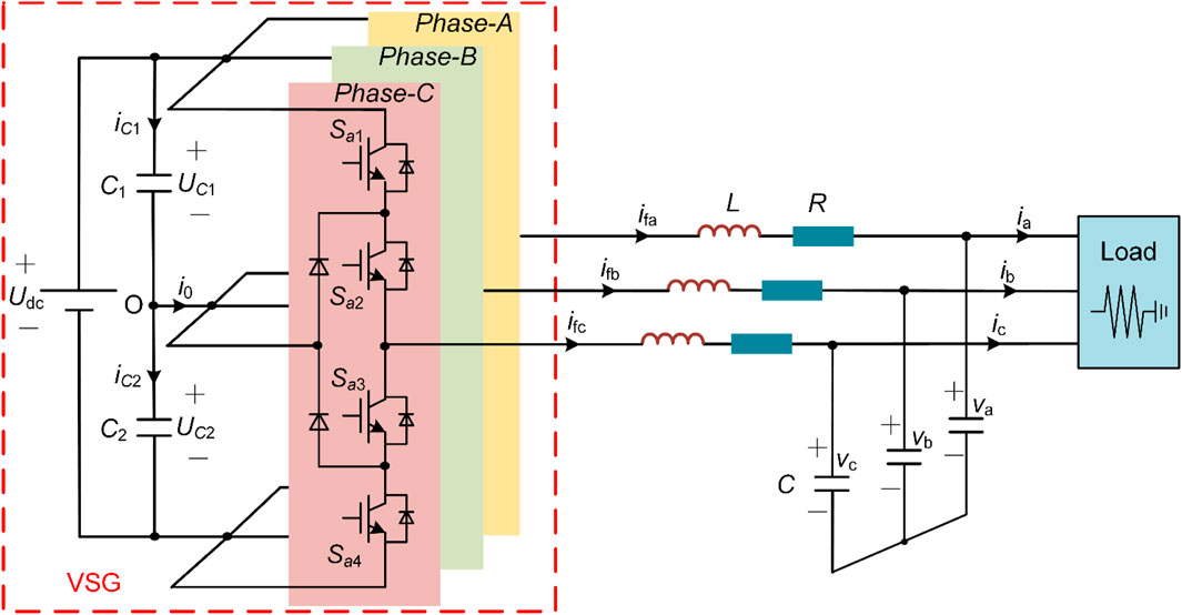
FIGURE 1. Topology of NPC three level VSG.
VSG frequency control is achieved through the rotor motion equation and the original machine adjustment equation. Assuming the pole pair number is 1, the mechanical angular velocity is equal to the electrical angular velocity, and the rotor motion equation can be expressed as,
where J is the moment of inertia, D is the damping coefficient, Pm is the mechanical power, Pe is the electromagnetic power, ω is the actual angular velocity, ω0 is the rated angular velocity, and θ is the virtual power angle.
To more accurately simulate the characteristics of a synchronous generator, the original machine adjustment equation is added to the VSG frequency control. The P-f droop characteristic can be obtained through the equation.
where Pref is the active input reference value, and m is the active droop control coefficient.
Based on Eqs 1, 2, the active frequency control of VSG is formed.
The VSG given output voltage E can be obtained through the Q-U droop characteristic as
where UN is the rated voltage, n is the reactive voltage droop coefficient, Qref is the reactive input reference value, and Q is the VSG output reactive power.
Based on Eq. 3, the reactive voltage control of VSG is formed.
After obtaining the power angle and amplitude from the active and reactive loops of VSG, the three-phase voltage value v* can be obtained as
To approximate the quasi-static characteristics of a synchronous machine (D’Arco et al., 2015), a virtual impedance loop is introduced, which is described as follows.
where, vd_ref and vq_ref represent the components of VSG output voltage reference value in the dq coordinate system.
Adding a virtual impedance block can make the output characteristics of the inverter source more similar to that of a traditional synchrotron. This is conducive to power decoupling, accurate power distribution, suppression of circulating current, and improvement of virtual synchronous machine stability.
When the islanded microgrid is subject to significant power disturbances, VSG control becomes crucial. Figure 2 shows the frequency response of different load levels connected to the system under fixed parameters.
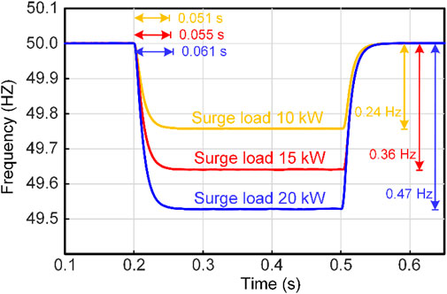
FIGURE 2. Frequency response of different load levels connected to the system.
It can be seen that as the load level increases, the frequency of the system gradually decreases, and the adjustment time for the system frequency to reach the new steady state is slightly increased. This indicates that fixed parameters can provide a certain degree of inertia and damping, but they have limited frequency regulation and control flexibility. Therefore, when designing a VSG controller, adjusting the inertia coefficient J and the damping coefficient D appropriately is very advantageous for frequency regulation.
Figure 3 shows the effects of different virtual inertia and damping on the frequency response of the system under sudden load increase.
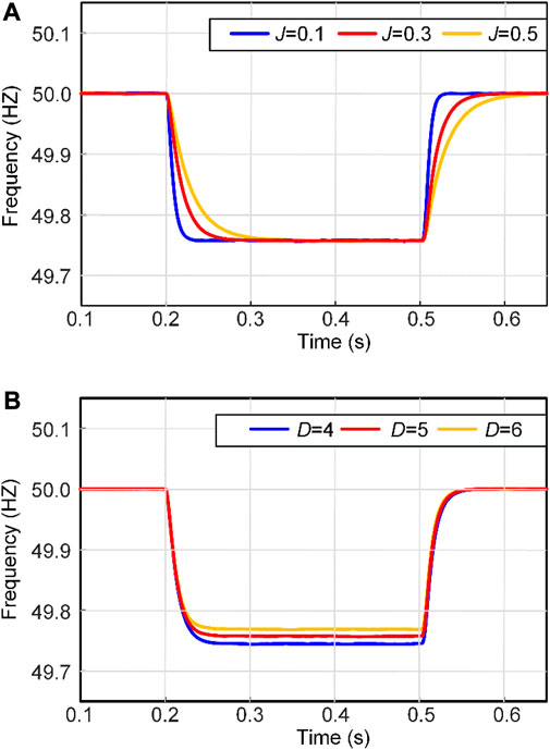
FIGURE 3. The influence of parameters J and D on the system frequency response. (A) Frequency characteristic curves of different J systems; (B) Frequency characteristic curves of different D systems.
From Figure 3A, it can be seen that with the virtual damping coefficient fixed, as the virtual inertia coefficient J increases, the frequency regulation time gradually increases. Combined with Figure 2, the higher the level of surge load, the greater the impact on the system frequency. Therefore, as the load increases, a larger inertia J can provide more adjustment time for the system frequency response.
Figure 3B indicates that with the virtual inertia coefficient fixed, as the virtual damping coefficient D increases, the deviation of system frequency gradually decreases. Excessive frequency deviation is not allowed in the power system. Therefore, the frequency deviation can be reduced by appropriately increasing the damping coefficient when the high power load is connected.
To address the issue of poor flexibility in fixed-parameter VSG control, an improved adaptive VSG adaptive parameter adjustment strategy is proposed in this paper. This strategy involves introducing the frequency deviation and frequency rate of change into the virtual parameters of VSG and adaptively adjusting the virtual inertia and damping coefficients of the VSG system to improve the frequency stability of microgrids during power transients. Figure 4 shows the changes in the power-angle characteristic curve, rotor speed change rate dω/dt, and rotor speed deviation ∆ω during system disturbance.

FIGURE 4. Schematic drawing of power angle curve and angular velocity curve of VSG. (A) Power Angle characteristic curve; (B) dω/dt and Δω characteristic curves when the system is disturbed.
In one oscillation cycle, it can be roughly divided into four stages (i.e., stages ①–④ in Figure 4B). In stage ①, the VSG rotor angular frequency ω is greater than the rated angular frequency ω0 and dω/dt>0. At this time, ω of the VSG continues to increase, and J needs to be increased to reduce ∆ω, where ∆ω(dω/dt) > 0. In stage ②, ω is still greater than ω0, but dω/dt < 0. J should be reduced to make |dω/dt| larger so that ω can approach ω0 more quickly. At this time, ∆ω(dω/dt) < 0. In Stage ③, the VSG rotor angular frequency ω is less than the rated angular frequency ω0, and dω/dt < 0. At this point, |∆ω| continues to increase, requiring an increase in J to reduce |∆ω|, where ∆ω(dω/dt) > 0. In Stage ④, ω is still less than ω0, but dω/dt > 0. J should be decreased to make |∆ω| smaller, allowing ω to approach ω0 more quickly. At this stage, ∆ω(dω/dt) < 0. Meanwhile, the frequency deviation of the system can be adjusted by controlling the damping coefficient D. As D increases, the frequency deviation of the system decreases. Therefore, when ∆ω changes, the damping coefficient D can be adjusted appropriately. The principles for selecting J and D in different stages are shown in Table 1.
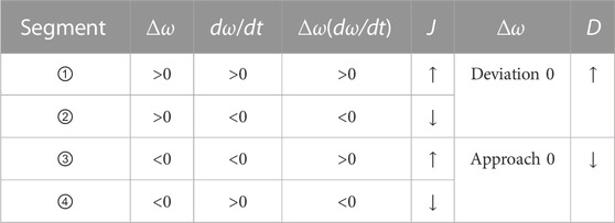
TABLE 1. Selecting principle of J and D.
Based on the above analysis, the values of the adaptive moment of inertia J and damping coefficient D should be related to ∆ω and dω/dt. According to the selection principles of virtual a moment of inertia and damping coefficient described in Table 1, the proposed parameter adaptive adjustment strategy can be expressed as
In the equation, J0 represents the virtual inertia at the steady state of VSG; D0 represents the damping coefficient at the steady state of VSG; Δω represents the angular velocity deviation; dω/dt represents the angular velocity change rate; k1 and k2 represent the virtual inertia adjustment coefficients; k3 and k4 represent the damping adjustment coefficients.
To accurately calculate the angular velocity change rate, this paper designs and uses a TD to obtain dω/dt. This method can accurately estimate the angular velocity change rate, avoiding excessive parameter fluctuations caused by rapid load power switching. This makes the response smoother and thus improves frequency stability. The second-order TD obtains two output signals v1(t) and v2(t) for the input signal v0(t), where v1(t) tracks the input signal v0(t), while v2(t) is actually the “generalized differentiation” of v0(t) that overcomes noise interference (Han, 2009).
The second-order TD is constructed as follows:
In Eq. 7,
where T is the integration step size, reducing T has a significant effect on suppressing noise amplification; r is the velocity factor, and the larger r is, the faster the tracking speed; h is the filtering factor, and increasing h can enhance the filtering effect.
Based on the above analysis, Eq. 6 can be expressed as
where v2(t) is the extraction of the rate of change of angular velocity calculated using TD. Figure 5 shows the adaptive parameter VSG active power frequency control block diagram designed in this paper.
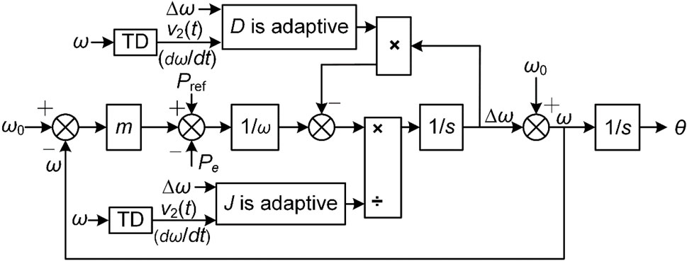
FIGURE 5. Adaptive parameter VSG active power frequency control method.
The traditional control methods for NPC three-level virtual synchronous generators often involve dual-loop control, where an inner loop controls the current and an outer loop regulates the voltage or power. Tuning the PI parameters for optimal performance can be a time-consuming and iterative process, requiring expertise and trial-and-error adjustments.
In contrast, the proposed VSG-MPC strategy eliminates the need for this dual-loop control architecture, resulting in a simplified and more straightforward control. This article derives a simplified mathematical model of NPC three-level VSG-MPC based on the principles of VSI and VSG.
According to Kirchhoff’s law, the mathematical model with LC output filter can be expressed in the αβ coordinate system as follows
In the equation, Uαβ, ifαβ, vαβ, iαβ and iCαβ respectively represent the inverter side voltage, current, load side voltage, current and current flowing through the filter capacitor in the αβ coordinate system.
When the NPC three-level inverter works normally, each bridge arm has three different operating modes, and the switching states of each bridge arm Si (i = a, b, c) are defined as
The NPC three-level inverter has 27 different switching states, which can generate 27 voltage vectors accordingly.
To predict the filter capacitor voltage, assuming a signal sampling period of Ts, we use a first-order Euler equation to discretize Eq. 10. After rearranging, we have
where ifαβ(k), vαβ(k), iαβ(k), and Uαβ(k) represent the converter side current, load side voltage and current, voltage vector at the k-th sampling time on the αβ axis, respectively. ifαβ(k+1) and vαβ(k+1) respectively represent the predicted value of inductance current and load side voltage in the k+1 sampling period under the αβ coordinate axis.
Assuming C1 = C2, uC1 and uC2 are the voltage of the two capacitors on the DC side, and iC1 and iC2 are the currents flowing through the two capacitors on the DC side. i0 is the midpoint current, and the reference direction is shown in Figure 1. iC1 and iC2 can be expressed as
The signal sampling period is defined as Ts, and the forward Euler method is used to discretize Eq. 13. After sorting out, we derived
where uC1(k) and uC2(k) represent the voltage values of the two capacitors on the DC side at time k. uC1(k+1) and uC2(k+1) respectively represent the predicted values of the DC side capacitor voltages at the time of k+1. iC1(k) and iC2(k) respectively represent the current values of the two capacitors flowing into the DC side at k time.
According to Kirchhoff’s current law, it can be depicted that
According to the assumption that C1 = C2. It can be deduced from Eqs 14, 15 that
where ∆uC(k+1) and ∆uC(k) are the voltage difference between the upper and lower capacitors on the DC side at time k+1 and time k.
Due to the delay between sampling and control, based on the output vector used in the k-th cycle, Eqs 12, 16 are further predicted to obtain vαβ(k+2) and ∆uC(k+2) to achieve delay compensation. After considering delay compensation, the design cost function g is
where vαβ_ref means αβ VSG output reference voltage under the coordinate axis; λ represents the DC side midpoint voltage weight coefficient.
Figure 6 shows the VSG control block diagram based on MPC. After calculating the VSG reference voltage in Eq. 5, calculate the predicted voltage of the filtering capacitor branch according to Eq. 12, and calculate the predicted midpoint voltage through Eq. 16. Finally, calculate the cost function value of the candidate vector through Eq. 17. The vector corresponding to the minimum cost function is the optimal vector Vopt. After outputting Vopt, VSG closed-loop control can be achieved.
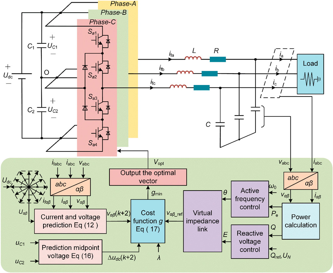
FIGURE 6. VSG control block diagram based on MPC.
In order to verify the effectiveness of the proposed strategy in frequency stability control of microgrid when the DC side midpoint voltage, the dynamic response speed of active power and the load power change, a simulation model was built using MATLAB/Simulink. The main parameters are shown in Table 2.
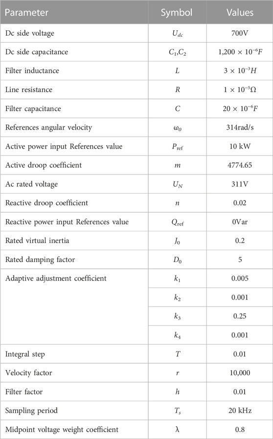
TABLE 2. The parameters of the proposed system.
Taking the load increase of 10 kW as an example, we compare the control performance of the traditional method with that of the proposed method. The initial load of the system is 10 kW, increase by 10 kW at 0.2 s, and cut off at 0.5 s. The comparison of SVPWM method and MPC method when load changes is shown in Figure 7.
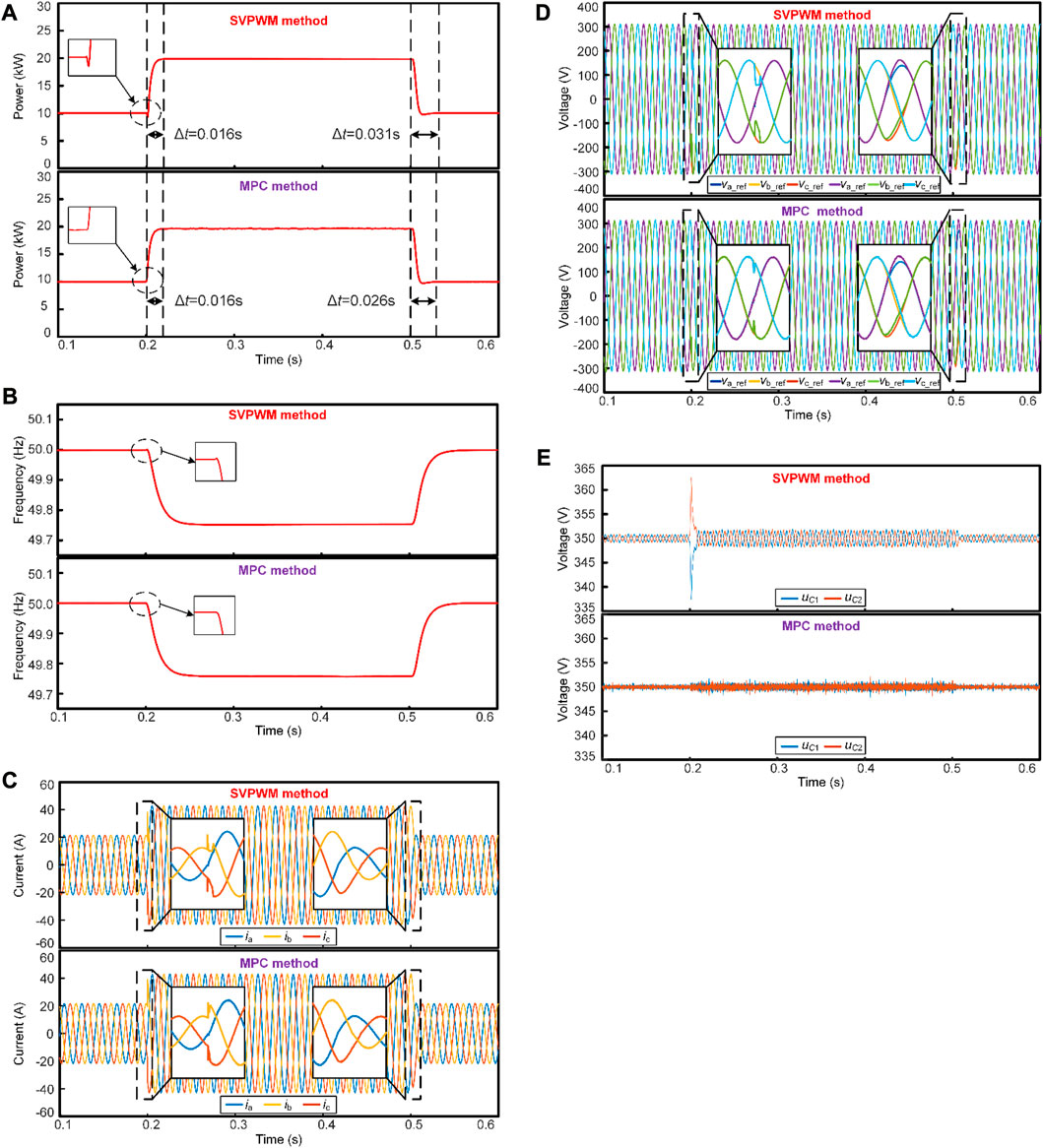
FIGURE 7. Comparison diagram of SVPWM method and MPC method when load changes. (A) Active power waveform comparison; (B) Frequency waveform comparison; (C) Load current waveform comparison; (D) VSG output voltage comparison; (E) Voltage comparison between two capacitors on the DC side.
Figure 7A shows the output power of VSG. Under the SVPWM method, it takes approximately 0.016 s for the active power to rise from 10 kW to 20kW, compared to 0.015 s for the MPC method. The load power is restored to 10kW, and the stable value is about 0.031 s by the SVPWM method, and 0.026 s by the MPC method. Figure 7B shows the system frequency. The frequency waveform of MPC method is better than that of SVPWM method at the moment of load power change. Figures 7C, D depict waveforms of load current and load voltage. It can be observed that both methods achieve effective control. As the load power increases from 10 kW to 20 kW, the load current rises from 20A to 40A. Similarly, when the load power decreases back to 10 kW, the load current reduces from 40A to 20A. The load voltage remains approximately at 311V and accurately tracks the voltage reference value. Figure 7E shows the voltage values of the two capacitors on the DC side. At a load power of 10 kW, the capacitive voltage of the MPC method is about 1.6 V, while that of the SVPWM method is about 4 V. When the load power is switched to 20 kW, the capacitive voltage of the MPC method is about 2.6 V, while that of the SVPWM method is about 6 V. The results indicate that MPC has a faster response speed in power regulation compared to SVPWM, and has smaller DC side voltage fluctuations.
By substituting the values in Table 2 into Eq. 9, the expression of J and D can be written as
Figure 8 shows a comparison of the J and D values obtained by applying the VSG angular velocity change rate and TD calculated by the discrete differentiator to the adaptive control strategy proposed in this paper when adding different levels of load.
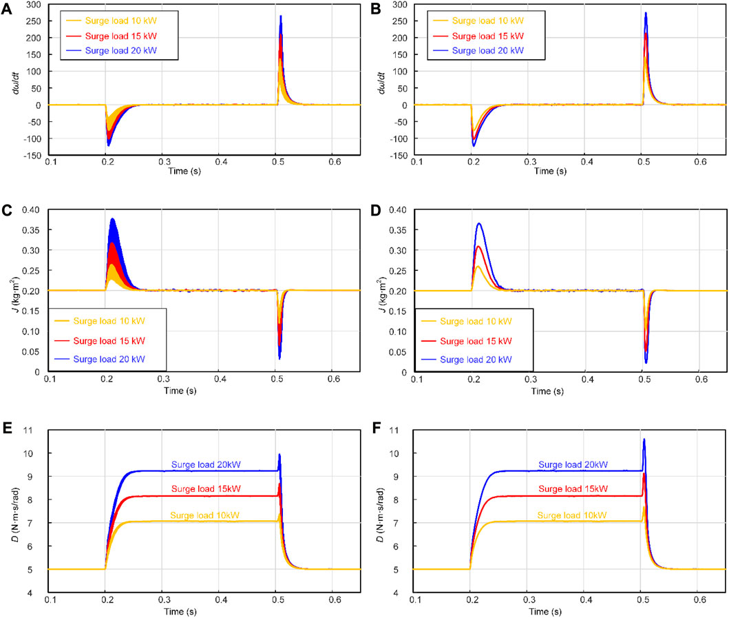
FIGURE 8. Rate of angular velocity change dω/dt, values of adaptive parameters J and D. (A) The discrete method calculates dω/dt; (B) The proposed method calculates dω/dt; (C) The discrete method calculates J; (D) The proposed method calculates J; (E) The discrete method calculates D; (F) The proposed method calculates D.
The angular velocity change rate calculated using the method proposed in this article will not experience significant oscillations during sudden changes in load power. Applying this method to the calculation of the adaptive parameters J and D can prevent oscillations in the angular velocity change rate from causing frequent parameter changes. When the load size changes, the adaptive parameter J will increase or decrease according to the frequency state of the system. When the frequency deviates from the normal value, the parameter D will adaptively adjust to reduce the frequency deviation.
Figure 9 shows the frequency waveform obtained according to the above adaptive adjustment strategy when different levels of load are applied.
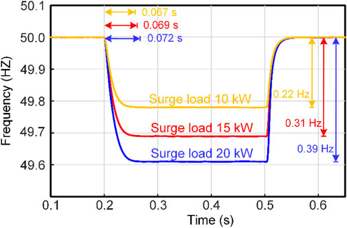
FIGURE 9. The frequency response of different levels of loads connected to the system using the proposed method.
Figure 9 shows the frequency response of the system under different load levels when using adaptive parameter J and D control strategies. Comparing Figure 2, it can be observed that as the load level increases, the adjustment time for the system frequency to reach the new steady-state increases and the frequency deviation decreases. In conclusion, the proposed adaptive VSG control strategy can effectively improve the dynamic performance and steady-state performance of the system frequency under sudden load changes.
In order to further verify the effectiveness of the proposed control strategy, a hardware in the loop semi physical experimental platform with NPC three-level VSG parameter adaptive structure was constructed, as shown in Figure 10. The experimental platform is composed of Typhoon602+and PE Expert4, and the control algorithm is executed on the PE Expert4 processor board composed of DSP and FPGA control chips.
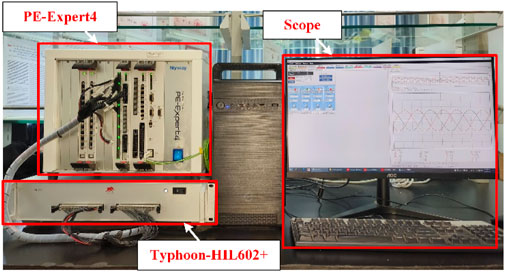
FIGURE 10. Hardware experimental platform for NPC three-level VSG.
Firstly, the performance when testing the actual load power variation is evaluated. Given an initial Pref of 10 kW and Qref of 0 Var, the load power is varied from 10 kW to 20 kW and then back to 10 kW. Figure 11 shows the variation process of VSG output power, frequency inertia, and load current when using the VSG-MPC proposed in this paper.
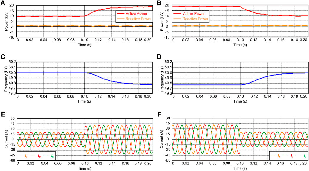
FIGURE 11. Experimental results of load power variation. (A) VSG outputs active and reactive power as load power increases; (B) VSG outputs active and reactive power as load power decreases; (C) Frequency waveform of load power increase; (D) Frequency waveform of load power decrease; (E) Load current waveform with load power increase; (F) Load current waveform with load power decrease.
As shown in Figure 11, when the load power changes, the VSG output power Pe changes from 10 kW to 20 kW; the reactive power Q fluctuates around 0 Var; the frequency decreases from 50 Hz to 49.77 Hz; and the load current increases from 20 A to 40 A. Correspondingly, when the load power changes from 20 kW to 10 kW, the VSG output power also changes from 20 kW to 10 kW; the reactive power fluctuates slightly; the frequency increases from 49.77 Hz to 50 Hz; and the load current decreases from 40 A to 20 A. These experimental results demonstrate that the proposed VSG-MPC strategy can achieve good active-power frequency regulation.
Next, the MPC performance is tested, and Figure 12 shows the control results of the DC-side capacitor voltage and the load voltage during the load power switch.
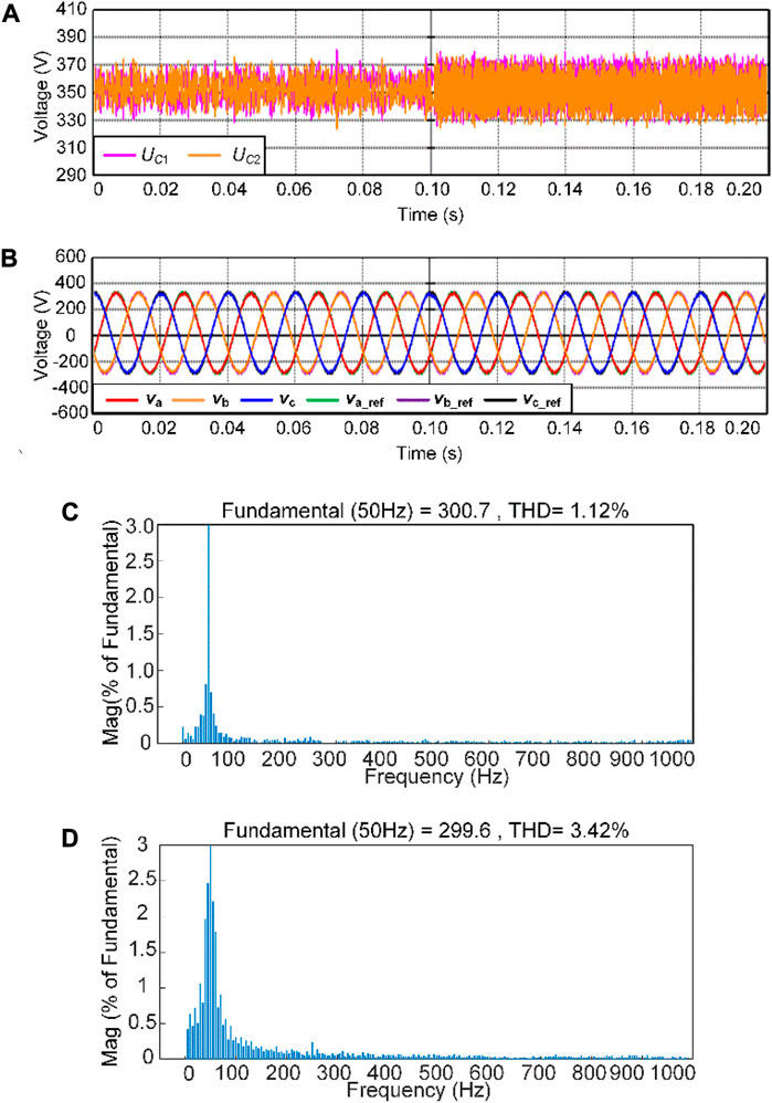
FIGURE 12. Experimental results of model predictive control. (A) Dc side capacitor voltage; (B) Reference value and actual value of load voltage; (C) Load power of 10 kW voltage spectrum; (D) Load power of 20 kW voltage spectrum.
Figure 12A shows the waveform of the DC-side capacitor voltage during load power variations. When the load is 10 kW, the capacitor voltage fluctuates by approximately 20 V. As the load power increases to 20 kW, the capacitor voltage fluctuates by approximately 40 V. Figure 12B depicts the waveform of the reference voltage and the actual voltage of the load, demonstrating that the actual voltage of the load tracks the voltage reference from the VSG output effectively. From the voltage spectrum plots in Figures 12C, D, it can be observed that when the load power is equal to the specified active power, the total harmonic distortion (THD) is 1.12%. As the load power increases to 20 kW, the magnitude of the fundamental harmonic slightly decreases, resulting in a THD of 3.42%. The experimental results indicate that the proposed VSG-MPC strategy effectively limits the DC-side capacitor voltage fluctuations and controls the load voltage.
Finally, the influence of adaptive parameters J and D on the system frequency is verified. Figure 13 shows the experimental results of the system frequency when different power loads are switched.
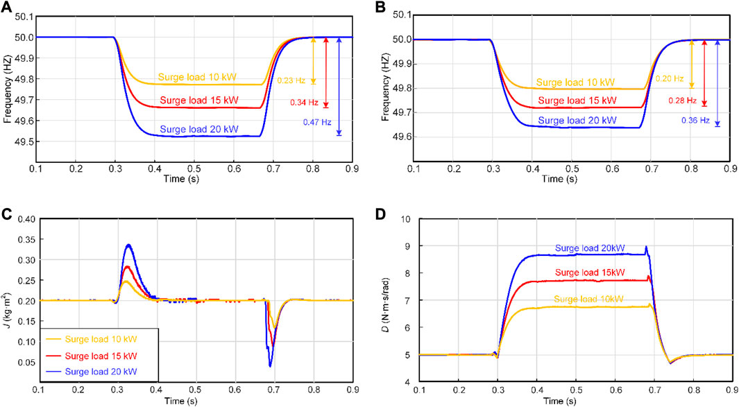
FIGURE 13. Experimental waveforms applying loads of different power levels. (A) Frequency response with fixed parameters; (B) Frequency response when adapting parameters; (C) The proposed method calculates J; (D) The proposed method calculates D.
The experimental waveform diagrams of frequency response are shown in Figures 13A, B for different power load connections and disconnections, using the fixed-parameter method and the proposed adaptive method, respectively. It can be observed that the designed adaptive adjustment method plays a crucial role in adjusting frequency deviation and time response. Figures 13C, D present the corresponding virtual inertia and damping coefficients during load connection and disconnection. J and D can be dynamically adjusted based on the real-time system load conditions, providing a more flexible control.
To enhance the frequency stability of an islanded microgrid and simplify the control structure, this study proposes an improved parameter adaptive model predictive control strategy for NPC three-level VSG.
The proposed strategy eliminates the need for dual-loop control and the complex modulation parameters associated with the PI controller. By calculating the angular velocity change rate using the designed TD, the problem of frequent changes in adaptive parameters during islanded load power switching is effectively addressed. Incorporating the angular velocity deviation and the aforementioned rate of change of angular velocity into virtual inertia and damping allows for adaptive adjustment of their parameters, resulting in improved dynamic characteristics of the system. The simulation and experimental results demonstrate that the proposed control strategy optimizes frequency support in an islanded microgrid and significantly enhances system stability.
The original contributions presented in the study are included in the article/Supplementary Material, further inquiries can be directed to the corresponding author.
XY has done the main theory research work. RW conceived the project and wrote the manuscript. NJ provided good advice and technical guidance for the manuscript; JZ, YC, and YL designed and participated in the experiment. All authors contributed to the article and approved the submitted version.
The authors gratefully acknowledge the support of the National Natural Science Foundation of China (Grant No. U2004166), Science and Technology Innovation Team in Universities of Henan Province (Grant No. 22IRTSTHN017), Henan Provincial Science and Technology Research Project (Grant Nos 212102210024 and 222102220064).
The authors declare that the research was conducted in the absence of any commercial or financial relationships that could be construed as a potential conflict of interest.
All claims expressed in this article are solely those of the authors and do not necessarily represent those of their affiliated organizations, or those of the publisher, the editors and the reviewers. Any product that may be evaluated in this article, or claim that may be made by its manufacturer, is not guaranteed or endorsed by the publisher.
Aguirre, M., Kouro, S., Rojas, C. A., and Vazquez, S. (2020). Enhanced switching frequency control in FCS-MPC for power converters. IEEE Trans. Industrial Electron. 68 (3), 2470–2479. doi:10.1109/tie.2020.2973907
Beck, H. P., and Hesse, R. (2007). “Virtual synchronous machine,” in Proceeding of the 2007 9th international conference on electrical power quality and utilization, Barcelona, Spain, October 2007 (IEEE), 1–6. doi:10.1109/EPQU.2007.4424220
Chen, L., Wang, R., Zheng, T., Guo, Y., and Mei, S. (2016). Optimal control of transient response of virtual synchronous generator based on adaptive parameter adjustment. Proc. CSEE 36 (21), 5724–5731. doi:10.13334/j.0258-8013.pcsee.160458
D’Arco, S., Suul, J. A., and Fosso, O. B. (2015). A Virtual Synchronous Machine implementation for distributed control of power converters in SmartGrids. Electr. Power Syst. Res. 122, 180–197. doi:10.1016/j.epsr.2015.01.001
Ding, M., Yang, X., and Su, J. (2009). Control strategies of inverters based on virtual synchronous generator in a microgrid. Automation Electr. Power Syst. (8), 89–93.
Guo, L., Chen, M., Li, Y., Wang, P., Jin, N., and Wu, J. (2022). Hybrid multi-vector modulated model predictive control strategy for voltage source inverters based on a new visualization analysis method. IEEE Trans. Transp. Electrification 9 (1), 8–21. doi:10.1109/tte.2022.3161583
Han, J. (2009). From PID to active disturbance rejection control. IEEE Trans. Industrial Electron. 56 (3), 900–906. doi:10.1109/tie.2008.2011621
Jiang, K., Su, H., Lin, H., He, K., Zeng, H., and Che, Y. (2020). A practical secondary frequency control strategy for virtual synchronous generator. IEEE Trans. Smart Grid 11 (3), 2734–2736. doi:10.1109/tsg.2020.2974163
Jin, N., Dai, D., Xie, H., Wu, J., and Guo, L. (2022a). Virtual vector-based FCS-MPC for NPC three-level grid-tied inverter without weighting factor of neutral-point voltage balancing. IEEE Access 10, 72806–72814. doi:10.1109/access.2022.3187994
Jin, N., Hou, Z., Xie, H., and Guo, L. (2022b). “Fault-tolerant model predictive control for neutral point clamped three-level virtual synchronous generator with AC current sensors Fault,” in Proceeding of the 2022 IEEE 5th International Electrical and Energy Conference (CIEEC), Nanjing, China, May 2022 (IEEE), 2401–2406. doi:10.1109/cieec54735.2022.9846406
Jun, E. S., Nguyen, M. H., and Kwak, S. S. (2020). Model predictive control method with NP voltage balance by offset voltage injection for three-phase three-level NPC inverter. IEEE Access 8, 172175–172195. doi:10.1109/access.2020.3024634
Jung, K., and Suh, Y. (2019). Analysis and control of neutral-point deviation in three-level NPC converter under unbalanced three-phase AC grid. IEEE Trans. Industry Appl. 55 (5), 4944–4955. doi:10.1109/tia.2019.2923379
Koiwa, K., Inoo, K., Zanma, T., and Liu, K. Z. (2021). Virtual voltage control of VSG for overcurrent suppression under symmetrical and asymmetrical voltage dips. IEEE Trans. Industrial Electron. 69 (11), 11177–11186. doi:10.1109/tie.2021.3125654
Li, D., Zhu, Q., Lin, S., and Bian, X. Y. (2016). A self-adaptive inertia and damping combination control of VSG to support frequency stability. IEEE Trans. Energy Convers. 32 (1), 397–398. doi:10.1109/tec.2016.2623982
Li, J., Wen, B., and Wang, H. (2019). Adaptive virtual inertia control strategy of VSG for micro-grid based on improved bang-bang control strategy. IEEE Access 7, 39509–39514. doi:10.1109/access.2019.2904943
Li, Z., and Jia, X. (2019). An improved VSG control strategy based on the amplitude-frequency characteristics of virtual power. IEEE Access 7, 101096–101105. doi:10.1109/access.2019.2930623
Pournazarian, B., Sangrody, R., Saeedian, M., Lehtonen, M., and Pouresmaeil, E. (2021). Simultaneous optimization of virtual synchronous generators (VSG) parameters in islanded microgrids supplying induction motors. IEEE Access 9, 124972–124985. doi:10.1109/access.2021.3111015
Sebaaly, F., Vahedi, H., Kanaan, H. Y., Moubayed, N., and Al-Haddad, K. (2016). Design and implementation of space vector modulation-based sliding mode control for grid-connected 3L-NPC inverter. IEEE Trans. Industrial Electron. 63 (12), 7854–7863. doi:10.1109/tie.2016.2563381
Shi, Q., Du, C., Sun, Y., Cai, W., Wang, A., and Chui, D. (2021). “An improved adaptive inertia and damping combination control of virtual synchronous generator,” in Proceeding of the IECON 2021–47th Annual Conference of the IEEE Industrial Electronics Society, Toronto, Canada, October 2021 (IEEE), 1–6. doi:10.1109/iecon48115.2021.9589784
Xu, H., Zhang, X., Liu, F., Shi, R., Yu, C., and Cao, R. (2017). A reactive power sharing strategy of VSG based on virtual capacitor algorithm. IEEE Trans. Industrial Electron. 64 (9), 7520–7531. doi:10.1109/tie.2017.2686374
Yan, S., Li, C., Cui, Y., Gao, X., and Cai, Y. (2022). An improved FCS-MPC based on virtual vector expansion and sector optimization for 2L-VSCs. IEEE Access 10, 127450–127460. doi:10.1109/access.2022.3227211
Ye, Z., Xu, Y., Wu, X., Tan, G., Deng, X., and Wang, Z. (2015). A simplified PWM strategy for a neutral-point-clamped (NPC) three-level converter with unbalanced DC links. IEEE Trans. Power Electron. 31 (4), 3227–3238. doi:10.1109/tpel.2015.2446501
Zhong, Q. C., and Weiss, G. (2010). Synchronverters: inverters that mimic synchronous generators. IEEE Trans. industrial Electron. 58 (4), 1259–1267. doi:10.1109/tie.2010.2048839
Zhou, L., Shuai, Z., Chen, Y., Wu, W., Zhou, X., Yan, K., et al. (2019). Impedance-based harmonic current suppression method for VSG connected to distorted grid. IEEE Trans. Industrial Electron. 67 (7), 5490–5502. doi:10.1109/tie.2019.2934084
Keywords: virtual synchronous generator (VSG), neutral point clamped (NPC), finite control set model predictive control (FCS-MPC), parameter adaptive, frequency regulation
Citation: Yang X, Wang R, Jin N, Zhao J, Cui Y and Li Y (2023) Parameter adaptive model predictive control strategy of NPC three-level virtual synchronous generator. Front. Energy Res. 11:1236646. doi: 10.3389/fenrg.2023.1236646
Received: 08 June 2023; Accepted: 24 August 2023;
Published: 04 September 2023.
Edited by:
Ali Sohani, University of Rome Tor Vergata, ItalyReviewed by:
Hamed Bizhani, Warsaw University of Technology, PolandCopyright © 2023 Yang, Wang, Jin, Zhao, Cui and Li. This is an open-access article distributed under the terms of the Creative Commons Attribution License (CC BY). The use, distribution or reproduction in other forums is permitted, provided the original author(s) and the copyright owner(s) are credited and that the original publication in this journal is cited, in accordance with accepted academic practice. No use, distribution or reproduction is permitted which does not comply with these terms.
*Correspondence: Xiaoliang Yang, eWFuZ3hsQGhudS5lZHUuY24=
Disclaimer: All claims expressed in this article are solely those of the authors and do not necessarily represent those of their affiliated organizations, or those of the publisher, the editors and the reviewers. Any product that may be evaluated in this article or claim that may be made by its manufacturer is not guaranteed or endorsed by the publisher.
Research integrity at Frontiers
Learn more about the work of our research integrity team to safeguard the quality of each article we publish.