 Francisco J. Montero
 Ravita Lamba
 Sarveshwar Singh4
 Wolfram Jahn
95% of researchers rate our articles as excellent or good
Learn more about the work of our research integrity team to safeguard the quality of each article we publish.
Find out more
ORIGINAL RESEARCH article
Front. Energy Res. , 07 September 2023
Sec. Solar Energy
Volume 11 - 2023 | https://doi.org/10.3389/fenrg.2023.1234548
In this paper, energy and exergy analysis of a bidirectional solar thermoelectric generator (STEG) coupled to a latent heat storage and cooling system (LHSCS) has been carried out. The effect of various parameters of LHSCS on energy and exergy efficiencies of STEG have been analysed under climatic conditions of Chile’s Atacama Desert. It is found that the most relevant design parameter to improve the energy and exergy efficiencies of the thermoelectric generator (TEG) is the container insulation, followed by heat sink at the TEG hot side, fin thickness and the aspect ratio of the container. The results showed that an optimally designed insulation container can improve the energy and exergy efficiencies of LHSCS by 30% and 200%, respectively, and the TEG conversion efficiency by 30% during nighttime. Further, inclusion of heat sink at TEG hot side during reverse operation of TEG at night can improve the TEG efficiency by 20%. The optimal fin thickness can improve the TEG conversion efficiency by 20% during the night and LHSCS energy and exergy efficiencies by 30% and 23%, respectively. The container geometry should have higher aspect ratios. This study may help in optimal design of LHSCS for solar energy conversion applications in the desert locations.
The thermal energy stored in solar thermal power plants has historically been used to supply the intermittency of daily and seasonal generation. Thermal energy can be stored in different media such as diffusive ground storage, inland storage, aquifers, phase change materials and water (Templeton et al., 2016). The thermal energy stored in solar thermal power plants has traditionally been used for domestic hot water (DHW) applications (Nordelland Hellström, 2000; Schmidt et al., 2004). Computational and numerical simulation models have been widely applied to study the thermal behavior of stored energy (McDowell and Thornton, 2008; Yang et al., 2011). However, some limitations are observed when storing thermal energy generated in solar thermal power plants. Among them, significant limitations are the need to maintain the temperature of the working fluid high enough to ensure the efficiency of the system (Templeton et al., 2016); the heat losses in a high-temperature thermal energy storage (TES) system (Sibbitt et al., 2012); and the dependence of the storage system temperature with the variation of the ambient temperature (Chapuis and Bernier, 2009).
The waste heat of solar PV and solar TEG can also be stored and utilized for heating applications depending on the operating temperature. Solar thermoelectric generators (STEG) are also used widely due to their compactness and robustness for small-scale solar energy generation. The significant limitations of STEG systems are the lower conversion efficiency, operational only during daytime, and maintaining lower temperature on the TEG cold side. To achieve a higher temperature difference between the hot and cold sides of the TEG, it is necessary to design a cooling system that helps to maintain the TEG cold side at a temperature of about 298 K (25 °C) during the operating hours. Further, since the STEG operates when the solar radiation is available, the residual heat from the TEG’s cold side can be stored and utilized in the STEG as a heat source in the absence of solar radiation, such as that proposed by Montero et al. (2021). Montero and Francisco. (2023) proposed a solar conversion system where the STEG is coupled to latent heat storage and cooling system (LHSCS) that uses a phase change material (PCM) and analyzed the transient effects of solar radiation, ambient temperature and wind speed of the Atacama Desert on the hot and cold side temperatures, voltage, power output and efficiency of STEG. Under these ambient conditions a maximum temperature difference of 120 °C is obtained between the TEG hot and cold sides and an average annual electricity generation of 5,735 Wh. The LCOE (Levelized Cost of Energy) and LCOS (Levelized Cost of Storage) of the studied system is found to be 8,850 and 566 USD/MWh, respectively.
The various factors that maximize the energy conversion efficiency are the geometry of PCM container, type of PCM based on working temperature, and properties of thermoelectric material. Previous studies reported that the maximization of TEG electricity output highly depends on the control of heat flow and coupling of internal and external resistances of TEG (Kiziroglouz et al., 2013). To maximize electricity generation from TEG in conjunction with PCM, it is necessary to select adequate dimensions of PCM container. Further, in some applications, the concentrated STEG operate at temperatures above 150°C, and therefore, there is a need to ensure efficient heat dissipation on its cold side. Tan et al. (2012) proposed a system in which the remaining heat from the thermoelectric system is transferred to the PCM material through a heat pipe connected to the cold side of the TEG. However, as the heat is expelled into the environment, there is no further storage or use of the remaining thermal energy, thus focusing solely on maintaining the TEG cold side at around 78 °C.
Shittu et al. (2019) developed a numerical model of a hybrid PV-TEG system with and without considering a flat plate heat pipe in COMSOL Multiphysics software and carried out the comparative performance analysis with the PV system only. Rodrigo et al. (2019) developed a thermal, electrical, and economic model of a concentrated PV-TEG (CPV-TEG) system by adjusting the TEG area. Mahmoudinezha et al. (2019) developed the numerical model of a hybrid CPV-TEG system having a triple-junction PV cell in COMSOL to analyze the transient behavior of hybrid system and verified the results by developing its experimental setup. The TEG contribution to overall power generation can be improved using geometrical and material optimization. Li et al. (2019) investigated the optimum TEG geometry for the maximized performance of the PV-TEG hybrid system and STEG system by developing a three-dimensional model of these systems with different TEG leg geometries.
Sun et al. (2017) proposed a real-time simulation model of flat-plate STEG to predict its daily performance under actual conditions and designed the experimental setup to validate and modify the simulation model. Abdo et al. (2019) developed a numerical model for the new configurations of PV and STEG modules integrated with a microchannel heat sink in a hybrid system and compared the performance of the proposed system with the conventional configuration of the CPV-TEG hybrid system. Lamba et al. (2023) explored heat sink (HS), PCM, and radiative cooling (RC) as the cooling options for the PV modules to achieve low and uniform temperature distribution along the PV and its improved performance. The authors studied and compared eight different combinations including HS, PCM, and RC for PV thermal management. Kumar et al. (2023) proposed the integration of PV, heat pipe (HP), TEG, RC systems for PV-TEG thermal management and its performance improvement by efficiently evacuating its residual heat using a heat pipe and a radiative cooler. The proposed system reduced the average PV operating temperature by 2°C for the Atacama Desert and by 13°C for Las Vegas. The maximum PV conversion efficiency and energy production improvements as compared to the PV alone system, are found to be 0.8% and 1.03% for the Atacama Desert, and 1.8% and 7.2% for Las Vegas. The anticipated range of LCOE for a hybrid PV-HP-TEG-RC system is found to be between 0.065–0.089 USD/kWh.
Shittu et al. (2020) developed a detailed 3-D model of a STEG system in COMSOL Multiphysics software to study the effects of non-uniform and transient heat flux on the STEG system performance. Escobar et al. (2021) proposed a low-temperature-based hybrid system that simultaneously generates electricity using a TEG and recovers heat from the sun with a thermosyphon used to maintain a constant temperature at the TEG cold side and recover heat from the condenser zone.
Wang et al. (2021) carried out the thermal management of the TEG systems by applying PCM to the hot side of TEG and compared the performance of the proposed model with the conventional TEG system without PCM. Rezania et al. (2020) developed a TEG integrated PCM system in a multiphysics simulation environment to investigate and optimize the performance of the proposed system. Maduabuchi et al. (2021) developed the simulation model of a STEG with tapered leg geometry under isoflux boundary conditions in ANSYS 2020 R2 software. The authors optimized the optical concentration ratio, thermoelectric leg area, height, and external load resistance to get maximum power output and energy efficiency from the proposed model.
Further, a TEG electricity generation system needs to use a minimum amount of input energy for its operation because the final energy conversion efficiency and the consequent technical and economic feasibility of the system depend on this input energy. Like other energy conversion systems based on renewable sources, the STEG requires an energy storage system that allows the extension of the electricity generation time and reduces the intermittency of electricity generation. The energy efficiency analysis of a latent heat storage (LHS) system relates the stored energy to the input energy in the system. However, energy efficiency may not be an appropriate measure. In contrast, exergy analysis provides an alternative means of evaluating and comparing the TES systems in a rational and meaningful way and thus, helping to improve and optimize the TES system designs, such as those made by different authors (Voller and Prakash, 1987; Carman, 1997; Groulx and Ogoh, 2009; Samara et al., 2012). The exergetic efficiency analyzes the energy flows according to their exergy content and separates the inefficiencies into those associated with effluent losses and irreversibilities, thus verifying a measure of the potential for improvement of the thermal system (Remeli et al., 2015). In an energy analysis, all losses are attributable to energy releases through the system limits; on the other hand, in an exergy analysis, the losses are divided into two types: those associated with exergy releases from the system and those related to internal exergy consumptions (Swaminathan and Voller, 1993).
Apart from these studies, a number of studies analyzed the energy and exergy efficiency for a variety of solar energy conversion systems and latent heat storage systems (Ramayya and Ramesh, 1998; Mehla and Yadav, 2017; Koca et al., 2019; Ergun, 2020; Mousa et al., 2020). These studies explored different approaches to enhance the energy/exergy efficiency of solar energy conversion and heat storage systems. The exergy efficiency evaluation helps in finding, measuring and controlling the irreversibilities in the heat transfer.
A few studies analyzed the energy and exergy efficiencies of a TEG system combined with a LHS system. Alghamdi et al. (2023) proposed a machine learning model trained with numerically generated data to analyze the transient exergy performance of PCM integrated with a concentrated TEG system. Hua Hong et al. (2023) explored the application of pulsed heat sources to a TEG-PCM hybrid system and evaluated the energy/exergy efficiency of the system under temperature limit and failure free-cycle times. These studies demonstrated the advantages of TEG-PCM hybrid system for energy generation and storage. Nevertheless, the thermoelectric generator and latent heat storage system need an indepth study of the different sources of irreversibilities that affect the efficiency and performance of both, energy conversion and storage.
It has been found in previous work that the waste heat of TEG or STEG stored in the PCMs is rejected to the environment using heat sinks. Furthermore, the energy and exergy efficiencies of these systems has not been carried out yet. This study proposes a STEG system in that its waste heat is stored in PCM and utilized during nighttime, which improves the overall performance of the STEG coupled with a latent heat storage (LHS) system. The transient model of the proposed system has been developed and the energy and exergy efficiencies have been determined.
The effect of container geometry (aspect ratio), container insulation thickness, fin thickness, natural convection in the PCM, and heat sink, have been analysed. The effect of these parameters has been analyzed by comparing the modified models with the base model and thus allowing to identify the best suitable model, which improves the conversion efficiency of the STEG system and TES efficiency of the LHSCS system. Thus, this study focuses on the analysis of a number of geometric and materials parameters to determine the best way to reduce the exergy releases from the system and the internal exergy consumptions. This parametric analysis shows some guidelines to design the LHS container, select the appropriate PCM and coupling the TEG energy conversion period with the energy storage period accordingly to a specific weather and insolation conditions of a selected place. Further, the effect of the heat convection phenomenon in the PCM has been analysed by calculating different dimensionless numbers.
The proposed model consists of a solar thermoelectric generator coupled with a latent heat storage system as shown in Figure 1. A Bismuth Telluride (Bi2Te3) based commercial thermoelectric (TE) module with dimensions of 40 mm-by-40 mm-by-5 mm, (Model: TE-MOD-5W5V-40S) manufactured by TEGPro, and consisting of 256 thermoelectric legs (128 pairs) has been considered. The thermal and geometrical properties of the TEG components are listed in Table 1. The lateral exterior border of the TEG module is filled with polymer insulation. The ceramic material is Alumina (Al2O3) which offers electrical insulation and improves heat transfer across the TE module.
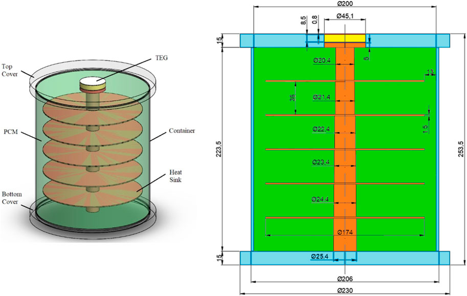
FIGURE 1. Components and dimensions (all dimensions are in mm) for the computational model of STEG + LHSCS system, previously studied by the authors (Montero et al., 2021).
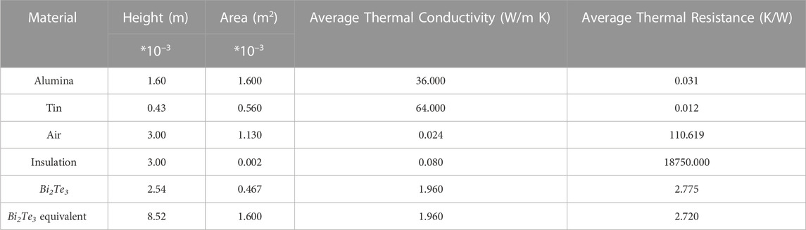
TABLE 1. Geometric and thermal properties of TEG components (Montero et al., 2021).
The TEG cold side is connected to the TES system for waste heat conduction from TEG to TES system through a heat sink. The TES system consists of a thermally insulated container and a copper heat sink inside the container. PCM is filled in the cylindrical insulated container of acrylic plastic. The heat sink consists of a solid copper bar and several copper radial fins. The heat sink is placed on the cylindrical container’s axis to build compartments filled with PCM, as shown in Figure 1. The Fresnel lens with a concentration ratio of 60 is used as a solar concentrator. The geometric model of the STEG coupled TES system is first built in SolidWorks, and then COMSOL Multiphysics is used to analyze the physics of the proposed model by importing the geometrical model from SolidWorks. Two PCMs used in this analysis are Puretemp 48X and Rubitherm RT62HC, which are manufactured by Puretemp LLC and Rubitherm Technologies GmbH, respectively. The PCMs are selected based on their melting temperatures and TEG cold side temperature. The optimum PCM melting temperature has been obtained from the analysis presented by De Lucia and Bejan (1990) which considered the geometric mean between the ambient and heat source temperatures. In this study, the TEG cold side temperature is around 80°C (heat source temperature) and the average ambient temperature is around 25 °C during solar irradiation hours in the Atacama Desert, which determines an optimum PCM melting temperature of around 48 °C. The use of the second PCM with a higher melting temperature allows to analyze the energy and exergy efficiency of the proposed system. The thermophysical properties of both PCMs are listed in Table 2. According to the manufacturer datasheets, the melting range is between 62 °C and 63 °C for RT62HC and fixed at 48 °C for Puretemp 48X.
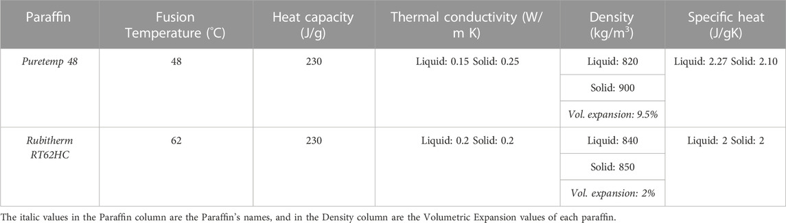
TABLE 2. Thermophysical properties of selected paraffins (Puretemp, 2023; Rubitherm. PCM RT-LINE, 2023).
The proposed model has been developed in COMSOL Multiphysics software previously by the authors (Montero et al., 2021). The governing equations of the STEG and LHS systems were presented in the previous authors' work. This section shows the governing equations for energy and exergy analysis of the proposed model.
The STEG energy efficiency (ηSTEG) is given in Eq. 1, and its exergy efficiency (εSTEG) can be obtained using the analysis previously presented in (Petela, 1964; Ejenakevwe et al., 2020; Song et al., 2019), which is given by Eq. 2.
where ψ, Ta, Tsun, PTEG, C, G and As respectively are the exergy of radiant energy received on TEG hot side, ambient temperature, Sun temperature, TEG power output, concentration ratio, solar radiation and the TEG surface area exposed to solar radiation.
The energy (ηLHSCS) and exergy (εLHSCS) efficiencies of the TES system are given as (Dincer and Rosen, 2002):
where Qout, LHSCS, Qin,LHSCS, A, l, kbar are the heat leaving and entering the TEG system, area, length, and thermal conductivity of copper bar, respectively. Tin, Tout, Qin,Ex_l and Qout, Ex_l are the temperatures at the ends of the copper bar, exergy losses in the container in the heat input and heat output periods of the LHSCS respectively. The suffix 1 and 2 correspond to presence and absence of solar radiation, respectively. The second period (i.e., absence of solar radiation) represents the inversion of the heat flow in the copper bar and, consequently, the Tin and Tout locations.
The aim of this analysis is to define the convective heat transfer coefficient (h) within each compartment and then an average heat transfer coefficient for LHSCS container. To calculate h, one must first obtain dimensionless numbers characteristic of the convective heat transfer phenomenon, including the Prandtl, Grashof, Rayleigh, and Nusselt numbers.
The Prandtl number, (Pr) relates the diffusion rate of momentum (viscosity) and the thermal diffusivity which is defined as:
Where Cp is the constant pressure thermal capacity of the phase change material, μ is the fluid’s dynamic viscosity, and k is the thermal conductivity. The average properties for the liquid state of the Puretemp 48X paraffin used in the numerical study are the following: Cp = 2,270 (J/kgK), μ = 0.008 (Pa s), k = 0.15 (W/mK). With these values, the average Prandtl number for the Puretemp 48X paraffin is 121.
The Grashof number (Gr) relates the buoyant and viscous forces that act in a fluid at a specific (local) point which is defined as:
where g, β, Ts, l and ν are the gravitational acceleration constant, volumetric expansion coefficient, surface temperature, characteristic length, and kinematic viscosity respectively. The average value of β and ν for Puretemp 48X paraffin are 0.002 K−1 and 9.4118 * 10–6 m/s2, respectively.
The Rayleigh number, Ra, relates the representativeness of heat transfer by conduction or convection within a fluid which is given as:
The local Nusselt number, Nux, relates heat transmission by convection from a surface in contact with a fluid with heat transfer if it occurred only by conduction which is defined as:
According to the correlations presented by Churchill & Chu, the Nusselt number can also be approximated for natural convection and Ra ≤ 109 as follows:
It is clear from Eq. 16 that the Nusselt number characterizes the natural convection phenomenon completely inside the LHSCS container.
The vertical wall presented by the copper bar of the heat sink in each compartment has been analyzed to define the characteristic length (l) and the local point (x) since the melting front of the PCM begins on that contact surface. The numerical analysis has been performed on an axisymmetric solid, assuming the results obtained in a vertical plane will be sufficient to approximate the dimensionless numbers. In this analysis, the midpoint of the copper bar in contact with each compartment has been chosen because this point represents the mean temperature of that section, as shown in Figure 2. Ts and Ta values are measured for the entire period studied (24 h), using the selected PCM in the LHSCS container for the summer (January) and winter (July) months. After obtaining the required temperatures, the dimensionless numbers are calculated for each compartment of paraffin.
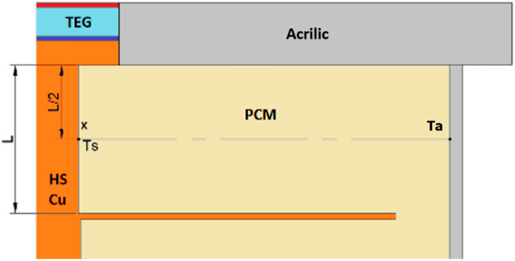
FIGURE 2. Location of the analysis point (x), surface temperature (Ts), and environmental temperature (Ta).
The two-dimensional numerical simulation of the proposed model is developed and solved in COMSOL Multiphysics software using the finite element method. The mesh analysis was conducted previously by Montero et al. (2021) to examine the mesh independency of the results. The heat transfer in a solid and liquid interface, electric current interface, laminar flow interface, and electrical circuit interface is used to perform the numerical simulation. The thermophysical properties of the PCM are defined separately for solid and liquid phases and coupled with the phase transition function.
This section presents the results obtained from the detailed energy and exergy analysis of the proposed model using two different PCMs. The energy and exergy efficiencies of the STEG, thermoelectric generator, and latent heat storage system have been evaluated separately.
Figure 3A shows the average monthly energy and exergy efficiencies of STEG using the monthly solar insolation of the Atacama Desert with Puretemp 48X. It has been found that the highest and lowest efficiency values are for November and July, respectively. This particularity is explained by the environmental and radiation conditions in the studied geographical location, with the highest and lowest average solar radiation observed at noon for November and July, respectively. Figure 3B shows the maximum monthly STEG energy and exergy efficiencies for Puretemp 48X with the highest and lowest values in February and November, respectively. As the average solar radiation for November is more elevated than in February, the energy and exergy efficiencies are more significant in November than in February. The average ambient temperature is higher for February than for November, allowing the environment’s heat losses to be lower in February. The average annual energy and exergy efficiencies are 1.48% and 1.58%, respectively, using Puretemp 48X paraffin as TES material.
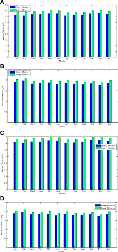
FIGURE 3. Average and maximum monthly energy (ηsteg) and exergy (εsteg) efficiencies of STEG respectively with (A, B) Puretemp 48X and (C, D) Rubitherm RT62HC.
Figure 3C shows the average monthly energy and exergy efficiencies of STEG for Rubitherm RT62HC. The highest and lowest average monthly values of energy and exergy efficiencies are observed in November and July, respectively, with Rubitherm RT62HC paraffin. Figure 3D shows the maximum monthly STEG energy and exergy efficiencies for Rubitherm RT62HC with the highest and lowest values in February and November, respectively. It is clear from Figure 3 that a similar monthly variation of the energy and exergy efficiencies has been observed for both types of paraffin. However, for Rubitherm RT62HC PCM, the monthly variation of the STEG maximum efficiency is more homogeneous. The latter is because the thermophysical properties reported by the manufacturer for RT62HC PCM are more homogeneous than for Puretemp 48X PCM, and the melting temperature is higher, which directly impacts the calculated efficiency values. The average annual STEG energy and exergy efficiencies using RT62HC PCM are 1.45% and 1.55%, respectively. These efficiency values are closer to those observed for Puretemp 48X paraffin.
Figure 4A shows the average monthly TEG energy conversion efficiency during the day and nighttime with Puretemp 48X. The TEG energy efficiency follows the same monthly variation observed in the STEG energy conversion efficiency, as shown in Figure 4A, according to the studied location’s climatic conditions and solar radiation. The TEG efficiency reaches an annual average of 3.98% during the solar radiation hours and 0.38% in the absence of solar radiation. The average monthly TEG energy conversion efficiency during the day and nighttime with Rubitherm RT62HC PCM for the monthly solar insolation of the Atacama Desert has been shown in Figure 4B. The TEG energy efficiency follows the same monthly variation observed in the STEG energy conversion efficiency, as shown in Figure 4B, according to the studied location’s climatic conditions and solar radiation. Using Rubitherm RT62HC as PCM, an average annual TEG energy conversion efficiency of 3.91% in the solar radiation period and 0.36% in the absence of solar radiation (TEG heat reversal flow) has been obtained shown in Figure 8. These TEG efficiency values have been validated with the theoretical efficiency values presented in the manufacturer’s technical datasheet. The TEG energy efficiency for the maximum temperature difference reached in the STEG coupled LHSCS (around 140 °C) was 4.4%. Therefore, the relative error between the calculated and theoretical average TEG efficiency is approximately 9.1%. It is possible to reduce the relative error if the maximum efficiency values are compared during the incidence of solar radiation. Thus, for example, for January and using Rubitherm RT62HC PCM, a maximum TEG conversion efficiency value of 4.6% is reached, and the relative error, in this case, is 4.5%. Using Puretemp 48X PCM and for January month average solar radiation, an efficiency of 4.63% is achieved, implying a relative error of 5.2% against the theoretical value. Therefore, comparing the calculated and the theoretical TEG efficiencies (presented by the manufacturer), the relative error was around 5%, which ensures the reliability of the values obtained in the numerical simulations of the STEG coupled LHSCS model.
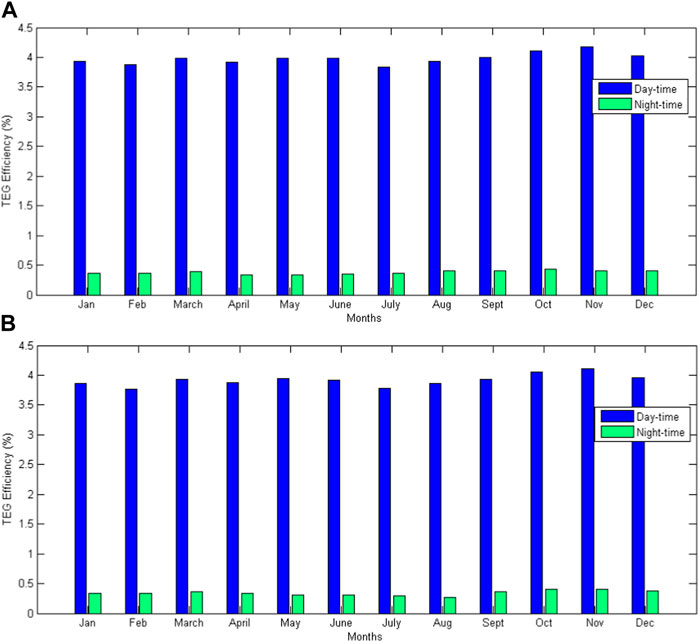
FIGURE 4. Average monthly TEG energy efficiency (ηteg) with (A) Puretemp 48X and (B) Rubitherm RT62HC.
The average monthly energy (ηLHSCS) and exergy (εLHSCS) efficiencies of LHSCS with Puretemp 48X and Rubitherm RT62HC as PCMs have been shown in Figure 5A, B, respectively. While using Puretemp 48X, the difference between energy and exergy efficiency was less pronounced, except in the winter months when the difference between the melting temperature of the Puretemp 48X (48°C) and the ambient temperature is more evident. Therefore, more energy losses to the environment were observed. When Rubitherm RT62HC was used as TES material, the efficiency curve showed a more pronounced variation in the winter months. Since the melting temperature (62°C) of Rubitherm RT62HC is higher than that of Puretemp 48X PCM, and thus, a more significant temperature difference is achieved between the container and the ambient temperature in the case of Rubitherm RT62HC PCM. Therefore, if the system achieves a more significant temperature difference between the environment and the paraffin inside the container, it implies an increase in LHSCS energy efficiency. The TES system showed a more considerable heat transfer from the container to the environment during the absence of solar radiation. However, it is counterproductive when evaluating the exergetic efficiency of the LHSCS since there are more heat losses to the environment, producing an increase in heat that does not perform any valuable work. The TES system achieves an average annual energy efficiency of 1.83% and 3.01% using RT62HC and Puretemp 48X respectively. The average yearly exergy efficiencies are 1.35% and 1.62% for the RT62HC and Puretemp 48X respectively.
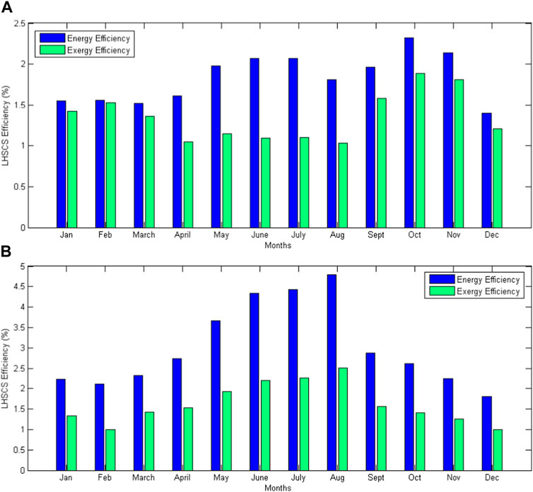
FIGURE 5. Average monthly LHSCS energy (ηLHSCS) and exergy (εLHSCS) efficiencies with (A) Puretemp 48X and (B) Rubitherm RT62HC.
For the parametric analysis of the proposed system, four cases have been considered by varying different parameters which are defined as follows.
• Case-1: Inclusion of heat convection in TES within the computational model of LHSCS
• Case-2: Variation in fins thickness with the reference thickness of 1.5 mm, the fin thickness of 2.25 mm is Case-3, configuration-1 and 0.75 mm is Case-3, configuration-2
• Case-3: Variation in aspect ratio of container (length and width) while maintaining a constant paraffin volume of 6,700 cm3.
• Case-4: Inclusion of a heat sink on TEG hot side.
Each of these cases has been considered while maintaining the container’s base geometry, as presented in Figure 1, except for the case of aspect ratio variation where all the container geometry is adjusted, including the internal heat sink (fins radius). Figure 6 shows the temperature variation of TEG hot side (Th) and TEG cold side (Tc) for these two fin thicknesses. The average percentage difference between the hot side temperatures of TEG is 0.93% and between the cold side temperatures of TEG is 4% for two different fin thicknesses. Given the slight difference between the calculated values for two different fin thicknesses, it has been decided to perform the energy and exergy efficiency analysis for a fin thickness of 2.25 mm since it is commercially available.
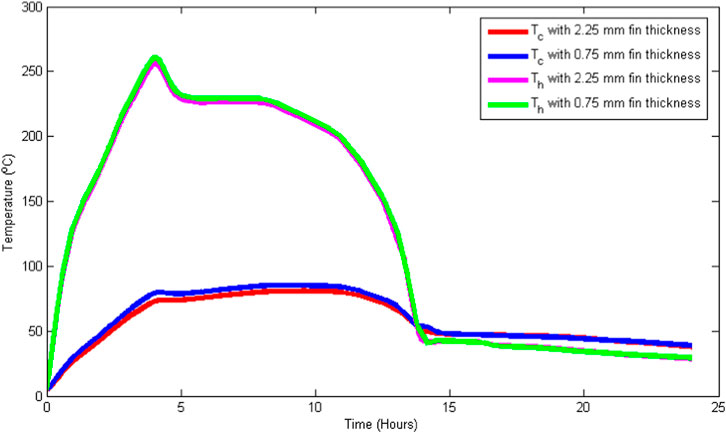
FIGURE 6. Effect of the fin thickness on the TEG hot (Th) and cold side (Tc) temperatures.
In the third case (Case-3), the aspect ratio was varied, and the PCM volume in the container has been fixed at around 6,700 cm3. This volume has been calculated with the 6 kg of PCM and the initial geometry of the container. Thus, the geometry variations have been carried out by varying the aspect ratio, considering the relationship between the length and the radius of the LHSCS container. If the length is reduced, the radius increases and vice versa. The energy and exergy analysis has been carried out by varying the container length by ±50% and keeping the volume constant. The initial length and radius of the container are 223.5 mm and 114.5 mm, respectively. Then, the first configuration in the third case corresponds to container length and radius of 111.75 mm and 141.42 mm, respectively, and the second configuration in the third case corresponds to container length and radius of 335.25 mm and 81.65 mm, respectively. In both cases of the third case, the solid PCM weight is 6 kg. Then, the energy and exergy efficiency analysis were carried out by varying the container’s geometry.
In the fourth case (Case-4), a heat sink was introduced at the hot side of the TEG (solar radiation receptor surface), and its effect was verified by increasing the heat transfer area at the TEG hot side to reject the waste heat to the environment during nighttime. The inclusion of a heat sink increases the heat transfer between the PCM contained in the LHSCS and the container’s outside environment. Since the ambient temperature of the geographic location cannot be controlled, the most feasible solution is to increase the transfer area so that more heat transfer can take place. However, there is a design compromise since the heat sink placed on the TEG hot side must not alter the amount of solar radiation received on this surface during the daytime. To overcome this design compromise, the heat sink should be designed in such a way that it does not change the solar radiation received on the TEG hot side surface.
The designed heat sink for case four has been shown in Figure 7A, and it is a 2 mm thick concentric fins of variable height. As the fins approach, the TEG center increases height, starting at 2 mm and ending at 10 mm. As previously mentioned, the thermoelectric module is modeled with a circular section adapting the area and volume of the elements according to the analysis carried out previously (Montero et al., 2021). This heat sink design allows the TEG hot side to receive approximately the same amount of solar radiation (by including a two-axis tracker) since the reception area would be the same as without a heat sink. The lateral area of the vertical walls of the heat sink helps increase the heat transfer area and, therefore, transfers a more significant amount of heat through the TEG in the absence of solar radiation. Thus, the effect of including a heat sink at the TEG hot side on the energy and exergy efficiencies has been analyzed.
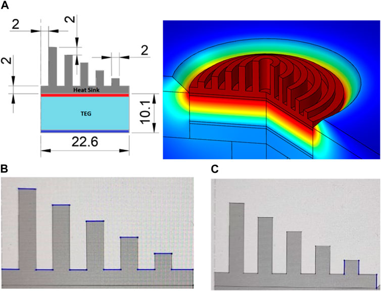
FIGURE 7. (A) Heat sink geometry at TEG hot side, 2D (left) and 3D (right) view (all dimensions are in mm); (B) horizontal and (C) minimum vertical surfaces lengths (2 mm each) considered for the evaluation of heat transfer coefficient at TEG hot side heat sink.
According to the correlations presented by Churchill and Chu (1975) given in Eqs 17, 18, the convective heat transfer coefficient can be approximated for natural convection adjacent to a vertical plane and to a horizontal plane, both for laminar and turbulent flow, respectively as follows:
The last equations were applied in the heat sink vertical and horizontal surfaces, as the border conditions for the simulation of the convective heat transfer considering the length and width of each fin, as shown in Figure 7B. Figure 7C shows only an example of the vertical surface length.
The convective heat transfer coefficient, h value was evaluated under the environment conditions of the studied location. The convective heat transfer varies not only under the environment conditions but also for the surface orientation of the heat sink. The vertical surfaces showed a convective heat convection coefficient approximated to the natural convection phenomena, on the other hand, the horizontal surfaces showed a convective heat transfer coefficient approximated to the forced convection phenomena. The average h value for all heat sink surfaces reaches around 45 W/m2K during the entire period. The details about h values are given in Table 3.
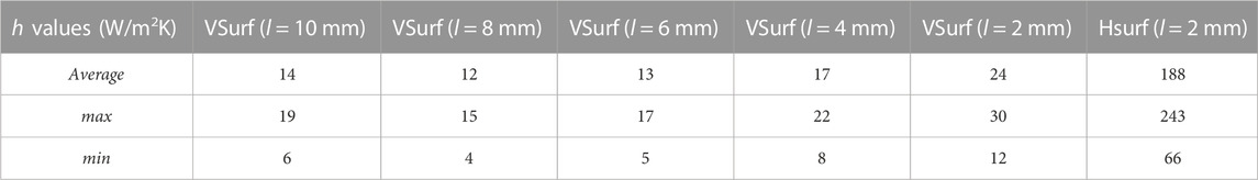
TABLE 3. Convective heat transfer coefficient evaluated at the TEG hot side heat sink, for vertical surface (VS.) and horizontal surface (HS).
The average convective heat transfer coefficient for all the vertical surfaces reaches 16 W/m2K which can be compared with that of obtained using the approximation presented by Duffie and Beckman (2013):
Using this approximation and the average wind velocity in the studied location of 6.3 m/s, the natural convection heat transfer coefficient reaches around 20.9 W/m2K. This value is around 30% higher than the one evaluated on the heat sink vertical surfaces in the computational simulation. If this value is compared with the total average heat sink coefficient, it represents around the half of the one evaluated in the computational simulation.
The latter means that the evaluated heat transfer coefficient is close to a natural convection value than forced convection value and that helps the system to reduce the heat losses to the environment during the presence of solar radiation without impact the increase in the temperature difference of the TEG sides during the absence of solar radiation.
The energy and exergy efficiency analyses of the LHSCS under four different cases have been carried out for the two types of paraffin for solar radiation of January in the Atacama Desert, and these efficiencies with Puretemp 48X have been shown in Figure 8A. For summer (January) and using Puretemp 48X, the variations of the energy and exergy efficiencies of the LHSCS with reference to the base case model, are 14.32% (ηLHSCS) and −33.62% (εLHSCS) for Case-1, 28.90% (ηLHSCS) and 22.87% (εLHSCS) for Case-2, 18.89% (ηLHSCS) and −2.57% (εLHSCS) for Case-3 (configuration-1) and 517% (ηLHSCS) and 527% (εLHSCS) for Case-4. Since the configuration-2 of Case-3, i.e., the container length and radius of 335.25 mm and 81.65 mm, respectively, do not allow the inversion of heat flow in the LHSCS, thus avoiding the heat discharge from the LHSCS towards the environment. Therefore, it is impossible to calculate the energy and exergy efficiencies of the LHSCS under the definitions stated in Eqs 4, 7 respectively. Thus, the parametric analysis shows a wide variation of the LHSCS efficiencies in Figure 9. The most significant variation occurs for the Case-4 model, which includes the heat sink on the TEG hot side to increase the overall heat transfer to the environment in the absence of solar radiation, which enables the operating efficiency of the LHSCS to be improved by about five times as compared to the base case model. The variation of the fin thickness in the Case-2 model allows for increasing the operating LHSCS energy efficiency by around 25%. The radial fins improve the heat transfer from the copper heat sink included in the LHSCS towards paraffin and vice versa. The LHSCS energy efficiency increases by around 20% when using a container with a wider aspect ratio than the base case model in Case-3 (configuration-1). In this configuration of Case-3, the container length is reduced, and the diameter is increased. The variation in exergy efficiency of LHSCS with this Case-3 model is reduced by around 2% compared to the base case model. In the Case-1 model, where the inclusion of heat convection in the computational model is considered, the LHSCS energy efficiency increases by about 14%, and the exergy efficiency decreases by about 33%. This is because, in the presence of solar radiation, the heat convection accelerates the melting of the phase change material in a shorter time. In other words, the TEG remaining heat is transmitted more effectively to the PCM. This results in storing a more significant amount of thermal energy in the PCM. Therefore, the LHSCS stores more heat to discharge during the absence of solar radiation, which causes an increase in the operating efficiency of the LHSCS. However, this also causes more heat losses to the environment, reducing the LHSCS operation’s exergy efficiency.
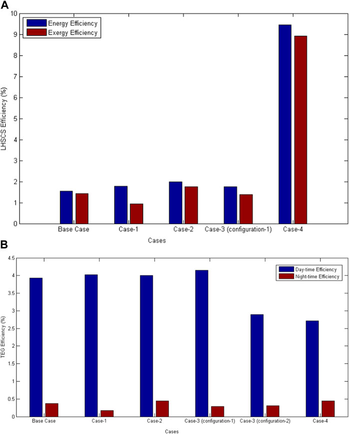
FIGURE 8. (A) LHSCS energy (ηLHSCS) and exergy (εLHSCS) efficiencies and (B) TEG energy efficiency under different cases with Puretemp 48X for January.
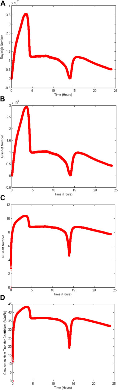
FIGURE 9. Transient variation of (A) Rayleigh number, (B) Grashof number, (C) Nusselt number and (D) convective heat transfer coefficient in the first compartment of the LHSCS with Puretemp 48X for summer (January).
The TEG conversion efficiency of the four cases is also different from that of the base case model. The TEG energy efficiency for all the four STEG coupled LHSCS model cases with Puretemp 48X for the average monthly solar insolation of summer (January) in the Atacama Desert has been shown in Figure 8B. The variations in the TEG energy efficiency can be verified for the period with the presence (daytime) and absence (nighttime) of solar radiation. The TEG energy efficiency for January under the different cases using Puretemp 48X in the LHSCS shows the following variations compared to the base case model. A variation of 2.29% (daytime) and −54.05% (night) for Case-1, 2.57% (daytime) and 15, 91% (nighttime) for Case-2, 5.50% (daytime) and −18.18% (nighttime) for Case-3 (configuration-1), −25.06% (daytime) and −20.69% (nighttime) for Case-3 (configuration-2) and −30.10% (daytime) and 41.18% (nighttime) for Case-4. The models showing the most significant increase and decrease in the calculated efficiencies are the fin thickness variation model (Case-2) and container geometry variation model (Case-3), respectively. The inclusion of heat convection within the numerical analysis in the Case-4 model radically reduces the energy efficiency of the TEG at night. The latter is related to the convection effects on the heat transfer to and from the heat sink coupled to the TEG. When the heat sink is added on the TEG hot side in Case-4, it increases the TEG efficiency at night but decreases the TEG efficiency during the daytime. The heat sink also allows more heat losses to the environment in the solar radiation period. In Case-3 (configuration-1), it is verified that it does not significantly impact the improvement of the TEG energy efficiency. On the contrary, it decreases it during the night.
The dimensionless numbers, given in Eqs 12–16 are also calculated for each compartment of paraffin after determining the required temperatures with Puretemp 48X. The average values of all the dimensionless numbers have been calculated for each compartment during the entire simulation time. The average value for the LHSCS container is obtained by taking the average of all the values of the five compartments. These dimensionless numbers for summer (January) and winter (July) have been listed in Table 4.
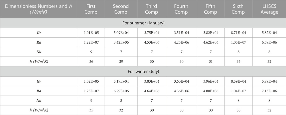
TABLE 4. Average dimensionless numbers and convective heat transfer coefficient in all the compartment and the LHSCS container for summer (January) and winter (July) months with Puretemp 48X.
Figure 9 shows the dimensionless numbers calculated in the study of heat convection in the LHSCS container filled with Puretemp 48X for the entire simulation period (24 h) for July. The heat convection affects the TEG energy efficiency andthe LHSCS exergy efficiency. Although the inclusion of heat convection within the numerical model allows a better approximation to the actual operation of the proposed model, it should be noted that there are some parameters such as the mushy zone constant (Amush) and the relationship for porous media of Carman & Koseny (At), which can be modified to have a model that is closer to the actual model. However, this requires more significant computational expenses when performing numerical simulations. These dimensionless numbers show that a natural heat convection phenomenon occurs within the compartments, thus verifying a laminar flow with the obtained average local Grashof number of (5.9 × 10⁴). The average Prandtl number of 121 corresponds to liquid paraffin, and finally, an average local Nusselt number of 8 verifies the preponderance of heat transfer by convection. The effect of insulation thickness verifies the implication of reducing the heat losses by convection towards the environment from the PCM container. Keeping the container wall’s initial insulation, an external insulation has been added that completely covers the container, including the end caps and an overlay on the acrylic wall. Thus, the insulation thickness has been varied from 1–4 cm by an increment of 1 cm to verify its impact on TEG and LHSCS efficiencies.
Figure 10A shows the effect of insulation thickness on LHSCS energy and exergy efficiencies for the summer (January) and winter (July) with Puretemp 48X. It has been found that these efficiencies increase with the increase in insulation thickness. For January with Puretemp 48X, the increment in LHSCS energy and exergy efficiencies are 0.58% (ηLHSCS) and 2.68% (εLHSCS), 27.51% (ηLHSCS) and 29.45% (εLHSCS) and 22.17% (ηLHSCS) and 23.40% (εLHSCS) for varying the insulation thickness from 1–2 cm, 2–3 cm and 3–4 cm respectively. Similarly, for July with Puretemp 48X, the increment in LHSCS energy and exergy efficiencies are 0.13% (ηLHSCS) and 0.58% (εLHSCS), 1.02% (ηLHSCS) and 1.21% (εLHSCS) and 0.70% (ηLHSCS) and 0.88% (εLHSCS) for varying the insulation thickness from 1–2 cm, 2–3 cm and 3–4 cm respectively. Therefore, it has been observed that the insulation thickness of 3 cm is the optimal thickness for this specific application of the LHSCS and Puretemp 48X for both the winter and summer periods. Figure 10B shows the effect of insulation thickness on the LHSCS energy and exergy efficiencies for the summer (January) and winter (July) with RT62HC. The thickness of container insulation has been varied to balance heat losses to the environment because increasing the insulation thickness may decrease the convective thermal resistance. It has been verified from Figure 10B that the optimal insulation thickness is 2 cm for this particular geometry of LHSCS and RT62HC PCM. For January with RT62HC PCM, the variations in the LHSCS energy and exergy efficiencies are −4.43% (ηLHSCS) and around 750% (εLHSCS), −26.54% (ηLHSCS) and −30.20% (εLHSCS) and 70.20% (ηLHSCS) and −70.62% (εLHSCS) for varying the insulation thickness from 1–2 cm, 2–3 cm and 3–4 cm respectively. Figure 10B shows that as container insulation thickness increases, the energy efficiency tends to decrease while the exergy efficiency tends to increase. The latter could lead to the optimum insulation thickness of either 3 or 4 cm. However, the most significant variation occurs when changing the insulation thickness from 1–2 cm. In this sense, and considering that the optimum LHSCS system must be operational throughout the year, it is chosen to maintain the optimum insulation thickness of 2 cm for July (winter) to coincide with the optimum insulation thickness for January (summer). Similarly, for July with RT62HC PCM, the percentage variations in the energy and exergy efficiencies of LHSCS are −4.93% (ηLHSCS) and 12.36% (εLHSCS), −7.42% (ηLHSCS) and 7.62% (εLHSCS) and 4.03% (ηLHSCS) and 11.51% (εLHSCS) for increasing the insulation thickness from 1–2 cm, 2–3 cm and 3–4 cm respectively.
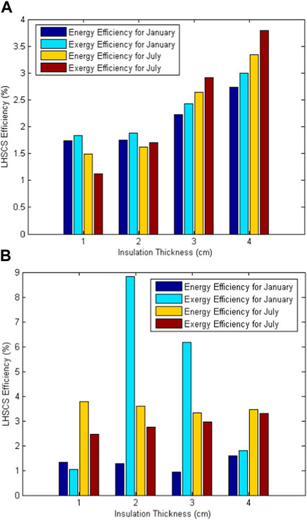
FIGURE 10. Effect of insulation thickness on the LHSCS energy (ηLHSCS) and exergy (εLHSCS) efficiencies with (A) Puretemp 48X and (B) RT62HC.
Figure 11A shows the effect of insulation thickness on the TEG energy efficiency during daytime and nighttime for the summer (January) and winter (July) with Puretemp 48X. It has been observed from Figure 11A that the effect of insulation thickness on the TEG energy efficiency during daytime and nighttime is minimal for summer (January) because TEG efficiency does not depend directly on the insulation container thickness. For this analysis, the optimum insulation thickness of 3 cm has been chosen for January to get maximum TEG energy efficiency and to follow the LHSCS efficiency results. For July with Puretemp 48X, the variations in the TEG energy efficiency are 0.27% (daytime) and 13.64% (nighttime), with insulation thickness changing from one to 2 cm, 0% (daytime), and 4% (nighttime) for insulation thickness changing from 2 to 3 cm and 0% (daytime) and 1.92% (nighttime) with insulation thickness changing from 3 to 4 cm. The optimum insulation thickness of 3 cm has been chosen for July to get maximum TEG energy efficiency. The optimum insulation thickness of 3 cm has been selected for the winter and summer periods and, therefore, for the entire year. Figure 11B shows the effect of insulation thickness on the TEG energy efficiency during daytime and nighttime for the summer (January) and winter (July) with RT62HC. It has been observed that the trend of TEG energy efficiency variation with RT62HC paraffin as storage material is similar to that of Puretemp 48X. The TEG energy efficiency variations with RT62HC for summer (January) are −0.26% (daytime) and 10.87% (night), 0% (daytime) and 5.88% (nighttime) and −0.26% (daytime) and 3.70% (nighttime) with insulation thickness varying from 1–2 cm, 2–3 cm and 3–4 cm respectively. The most significant improvement in TEG energy efficiency during nighttime occurs with insulation thickness changing from 1–2 cm, gradually decreasing with an increase in the insulation thickness. Therefore, the optimal insulation thickness of LHSCS container has been chosen to be 2 cm for LHCSC application at specific location of the Atacama Desert. Figure 11B shows that the TEG energy efficiency for winter (July) with RT62HC also follows the same trend for summer (January). The TEG energy efficiency variations with RT62HC for winter (July) are −0.54% (daytime) and 15.56% (nighttime), 0% (daytime) and 13.46% (nighttime) and 0% (daytime) and 3.39% (nighttime) with insulation thickness changing from 1–2 cm, 2–3 cm and 3–4 cm respectively. Therefore, the appropriate choice for optimum insulation thickness is 2 cm for summer and winter, thus, for the entire annual period.
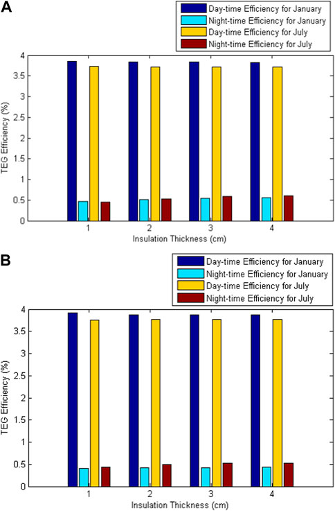
FIGURE 11. Effect of insulation thickness on the TEG energy efficiency with (A) Puretemp 48X and (B) RT62HC.
In this paper, the transient numerical model of STEG coupled LHSCS has been developed in COMSOL Multiphysics with two different PCMs under climatic conditions of the Atacama Desert. The proposed model operates in nighttime by utilizing waste heat of STEG stored in the LHSCS system during daytime. The energy and exergy efficiencies of the proposed system have been evaluated. The effect of the container geometry (aspect ratio), thickness of container insulation and fin, natural convection, and heat sink on the performance of the proposed system have been studied. The following findings are reported.
• The annual energy generated by the STEG coupled LHS system, using Puretemp 48X and RT62HC, is 5,785 Wh and 5,642 Wh, respectively.
• The average annual energy efficiency of the TEG with Puretemp 48X and RT 62HC is 3.98% and 3.91% during daytime and 0.38% and 0.34% during nighttime respectively.
• The average annual energy and exergy efficiencies of the LHSCS are 1.83% and 1.35% with Puretemp 48%X and 3.01% and 1.62% with RT62HC respectively.
• The energy efficiencies of the TEG with Puretemp 48X and the optimum insulation thickness of 3 cm are 3.87% and 0.42% during daytime and nighttime respectively for January, and 3.77% and 0.52% for July. Similarly, the energy efficiencies of the TEG with RT62HC and the optimum insulation thickness of 2 cm are 3.84% and 0.51% during daytime and nighttime respectively for January, and 3.71% and 0.52% for July.
• The most promising design model improvement is obtained by including a heat sink at the hot side of the TEG. This improves the heat transfer between the TEG and the environment and improves the energy generation during nighttime.
• At the optimum fin thickness, the average LHSCS and TEG efficiency improvements during daytime are 25% and 9% as compared to the base model.
• The container’s aspect ratio improves system’s efficiency when the container length is reduced and radius is increased to maintain the same paraffin volume.
• The obtained h value is close to the values obtained by other authors in the analysis of paraffin-based TES systems.
Thus, this analysis shows the relevance of each LHSCS design parameter to improve the TEG, STEG, and LHSCS energy and exergy efficiencies and gives some guidelines to focus the design of solar energy conversion and storage systems. Further, as the future scope of this work, other hybrid system configurations can be proposed to take advantage of the solar energy conversion systems waste heat to enhance its energy conversion efficiency. The residual heat of LHSCS can also be used in another thermal applications. Moreover, the heat sink design can be improved by using the constructal theory and the performance can be analyzed using different types of PCM including biodegradable PCM as well. The TEG system performance can also be improved by employing proper thermal management mechanism using passive radiative cooling.
The original contributions presented in the study are included in the article/Supplementary Material, further inquiries can be directed to the corresponding authors.
FM contributed to conceptualization, methodology, software and writing—original draft preparation. RL contributed to conceptualization, visualization, investigation, methodology, writing—reviewing and editing. SS contributed to visualization, investigation, writing—reviewing and editing WJ and W-HC supervised this work. All authors contributed to the article and approved the submitted version.
The authors would like to thank Pontificia Universidad Católica de Chile (PUC) for supporting this work.
The authors declare that the research was conducted in the absence of any commercial or financial relationships that could be construed as a potential conflict of interest.
All claims expressed in this article are solely those of the authors and do not necessarily represent those of their affiliated organizations, or those of the publisher, the editors and the reviewers. Any product that may be evaluated in this article, or claim that may be made by its manufacturer, is not guaranteed or endorsed by the publisher.
The Supplementary Material for this article can be found online at: https://www.frontiersin.org/articles/10.3389/fenrg.2023.1234548/full#supplementary-material
Abdo, A., Ookawara, S., and Ahmed, M. (2019). Performance evaluation of a new design of concentrator photovoltaic and solar thermoelectric generator hybrid system. Energy Convers. Manag. 195, 1382–1401. doi:10.1016/j.enconman.2019.04.093
Ahmet, K., Hakan, F., Tansel, K., and Yasin, V. (2007). Energy and exergy analysis of a latent heat storage system with phase change material for a solar collector. Renew. Energy 33, 567–574. doi:10.1016/j.renene.2007.03.012
Alghamdi, H., Maduabuchi, C., Mbachu, D., Albaker, A., Alatawi, I., Alsenani, T., et al. (2023). Machine learning model for transient exergy performance of a phase change material integrated-concentrated solar thermoelectric generator. Appl. Therm. Eng. 228, 120540. doi:10.1016/j.applthermaleng.2023.120540
Carman, P. C. (1997). Fluid flow through granular beds. Chem. Eng. Res. Des. 75, S32–S48. doi:10.1016/s0263-8762(97)80003-2
Chapuis, S., and Bernier, M. (2009). Seasonal storage of solar energy in borehole heat exchangers. Elev. Int. IBPSA Conf., 599–606.
Churchill, S. W., and Chu, H. H. (1975). Correlating equations for laminar and turbulent free convection from a vertical plate. Int. J. heat mass Transf. 18 (11), 1323–1329. doi:10.1016/0017-9310(75)90243-4
De Lucia, M., and Bejan, A. (1990). Thermodynamics of energy storage by melting due to conduction or natural convection. J. Sol. Energy Eng. 112 (2), 110–116. doi:10.1115/1.2929642
Dincer, I., and Rosen, M. (2002). Thermal energy storage: Systems and applications. China: John Wiley and Sons.
Ejenakevwe, K. A., Mgbemene, C. A., Njoku, H. O., and Ekechukwu, O. V. (2020). Parametric optimization of exergy efficiency in solar thermoelectric generators. J. Electron. Mater. 49 (5), 3063–3071. doi:10.1007/s11664-020-08021-0
Ergün, A. (2020). Energy and exergy analysis of a PV/thermal storage system design integrated with nano-enhanced phase changing material. Int. J. Exergy 32, 82–101. doi:10.1504/ijex.2020.107745
Escobar, P. V., Oyarzun, D. I., Arias, A., and Guzmán, A. M. (2021). Experimental study of a hybrid solar thermoelectric generator energy conversion system. Energy Convers. Manag. 238, 113997. doi:10.1016/j.enconman.2021.113997
Groulx, D., and Ogoh, W. (2009). Solid-liquid phase change simulation applied to a cylindrical latent heat energy storage system. InCOMSOL Conf.
Hong, B., Cai, Y., He, J., Huang, X., Wang, W., and Zhao, F. (2023). Energy and exergy analysis of phase change material based thermoelectric generator with pulsed heat sources. Appl. Therm. Eng. 231, 120924. doi:10.1016/j.applthermaleng.2023.120924
Kiziroglou, M. E., Elefsiniotis, A., Wright, S. W., Toh, T. T., Mitcheson, P. D., Becker, T., et al. (2013). Performance of phase change materials for thermal energy storage thermoelectric harvesting. Appl. Phys. Lett. 103 (19), 193902. doi:10.1063/1.4829044
Lamba, R., Montero, F. J., Rehman, Tu., Singh, S., and Manikandan, S. (2023). PCM-based hybrid thermal management system for photovoltaic modules: A comparative analysis. Environ. Sci. Pollut. Res., 113. doi:10.1007/s11356-023-27809-1
Li, G., Shittu, S., Ma, X., and Zhao, X. (2019). Comparative analysis of thermoelectric elements optimum geometry between photovoltaic-thermoelectric and solar thermoelectric. Energy 171, 599–610. doi:10.1016/j.energy.2019.01.057
Lv, S., He, W., Hu, Z., Liu, M., Qin, M., Shen, S., et al. (2019). High-performance terrestrial solar thermoelectric generators without optical concentration for residential and commercial rooftops. Energy Convers. Manag. 196, 69–76. doi:10.1016/j.enconman.2019.05.089
Maduabuchi, C., Njoku, H., Eke, M., Mgbemene, C., Lamba, R., and Ibrahim, J. S. (2021). Overall performance optimisation of tapered leg geometry based solar thermoelectric generators under isoflux conditions. J. Power Sources 500, 229989. doi:10.1016/j.jpowsour.2021.229989
Mahmoudinezhad, S., Atouei, S. A., Cotfas, P. A., Cotfas, D. T., Rosendahl, L. A., and Rezania, A. (2019). Experimental and numerical study on the transient behavior of multi-junction solar cell-thermoelectric generator hybrid system. Energy Convers. Manag. 184, 448–455. doi:10.1016/j.enconman.2019.01.081
McDowell, T. P., and Thornton, J. W. (2008). Simulation and model calibration of a large-scale solar seasonal storage system. Proc. SimBuild 3 (1), 174–181.
Mehla, N., and Yadav, A. (2017). Energy and exergy analysis of a PCM-based solar powered winter air conditioning using desiccant wheel during nocturnal. Int. J. Sustain. Eng. 11, 54–64. doi:10.1080/19397038.2017.1370033
Montero, F. J., Lamba, R., Ortega, A., Jahn, W., and Guzmán, A. M. (2021). A novel 24-h day-night operational solar thermoelectric generator using phase change materials. J. Clean. Prod. 296, 126553. doi:10.1016/j.jclepro.2021.126553
Montero Francisco, J., Ravita, Lamba, Ortega, Alfonso, Wolfram, Jahn, Wei-Hsin, Chen, and Guzmán Amador, M. (2023). A bidirectional solar thermoelectric generator combining heat storage for daytime and nighttime power generation. Appl. Therm. Eng., 224, 119997.
Mousa, W., Hussein, F., and Faraj, J. (2020). Energy and exergy analysis of a multi-PCM solar storage system. J. Adv. Res. Fluid Mech. Therm. Sci. 78, 60–78. doi:10.37934/arfmts.78.1.6078
Nordell, B. O., and Hellström, G. (2000). High temperature solar heated seasonal storage system for low temperature heating of buildings. Sol. energy 69 (6), 511–523. doi:10.1016/s0038-092x(00)00120-1
PureTemp (2023). PureTemp technical and safety data sheets. Available at: https://puretemp.com/?p=220.
Ramayya, A., and Ramesh, K. (1998). Exergy analysis of latent heat storage systems with sensible heating and subcooling of PCM. Int. J. Energy Res. 22, 411–426. doi:10.1002/(sici)1099-114x(199804)22:5<411::aid-er367>3.3.co;2-h
Ramesh, Kumar, Montero Francisco, J., Ravita, L., Manish, V., and Sushant, U. (2023). Thermal management of photovoltaic-thermoelectric generator hybrid system using radiative cooling and heat pipe. Appl. Therm. Eng. 227, 1359–4311. doi:10.1016/j.applthermaleng.2023.120420
Remeli, M. F., Tan, L., Date, A., Singh, B., and Akbarzadeh, A. (2015). Simultaneous power generation and heat recovery using a heat pipe assisted thermoelectric generator system. Energy Convers. Manag. 91, 110–119. doi:10.1016/j.enconman.2014.12.001
Rezania, A., Atouei, S. A., and Rosendahl, L. (2020). Critical parameters in integration of thermoelectric generators and phase change materials by numerical and Taguchi methods. Mater. Today Energy 16, 100376. doi:10.1016/j.mtener.2019.100376
Rodrigo, P. M., Valera, A., Fernández, E. F., and Almonacid, F. M. (2019). Performance and economic limits of passively cooled hybrid thermoelectric generator-concentrator photovoltaic modules. Appl. energy 238, 1150–1162. doi:10.1016/j.apenergy.2019.01.132
Rubitherm. PCM RT-LINE (2023). Available at: https://www.rubitherm.eu/en/index.php/productcategory/organische-pcm-rt.
Samara, F., Groulx, D., and Biwole, P. H. (2012). “Natural convection driven melting of phase change material: comparison of two methods,” in InExcerpt from the proceeding of the COMSOL conference.
Schmidt, T., Mangold, D., and Müller-Steinhagen, H. (2004). Central solar heating plants with seasonal storage in Germany. Sol. energy 76 (1-3), 165–174. doi:10.1016/j.solener.2003.07.025
Shittu, S., Li, G., Xuan, Q., Xiao, X., Zhao, X., Ma, X., et al. (2020). Transient and non-uniform heat flux effect on solar thermoelectric generator with phase change material. Appl. Therm. Eng. 173, 115206. doi:10.1016/j.applthermaleng.2020.115206
Shittu, S., Li, G., Zhao, X., Akhlaghi, Y. G., Ma, X., and Yu, M. (2019). Comparative study of a concentrated photovoltaic-thermoelectric system with and without flat plate heat pipe. Energy Convers. Manag. 193, 1–14. doi:10.1016/j.enconman.2019.04.055
Sibbitt, B., McClenahan, D., Djebbar, R., Thornton, J., Wong, B., Carriere, J., et al. (2012). The performance of a high solar fraction seasonal storage district heating system–five years of operation. Energy Procedia 30, 856–865. doi:10.1016/j.egypro.2012.11.097
Sun, D., Shen, L., Yao, Y., Chen, H., Jin, S., and He, H. (2017). The real-time study of solar thermoelectric generator. Appl. Therm. Eng. 119, 347–359. doi:10.1016/j.applthermaleng.2017.03.075
Swaminathan, C. R., and Voller, V. R. (1993). On the enthalpy method. Int. J. Numer. Methods Heat Fluid Flow 3, 233–244. doi:10.1108/eb017528
Tan, L., Singh, R., and Akbarzadeh, A. (2012). Thermal performance of two-phase closed thermosyphon in application of concentrated thermoelectric power generator using phase change material thermal storage. Front. Heat Pipes (FHP) 2 (4). doi:10.5098/fhp.v2.4.3001
Templeton, J. D., Hassani, F., and Ghoreishi-Madiseh, S. A. (2016). Study of effective solar energy storage using a double pipe geothermal heat exchanger. Renew. Energy 86, 173–181. doi:10.1016/j.renene.2015.08.024
Voller, V. R., and Prakash, C. (1987). A fixed grid numerical modelling methodology for convection-diffusion mushy region phase-change problems. Int. J. heat mass Transf. 30 (8), 1709–1719. doi:10.1016/0017-9310(87)90317-6
Wang, J., Song, X., Ni, Q., Li, X., and Meng, Q. (2021). Experimental investigation on the influence of phase change material on the output performance of thermoelectric generator. Renew. Energy 177, 884–894. doi:10.1016/j.renene.2021.06.014
Yang, W., Zhu, J., Shi, M., and Chen, Z. (2011). Numerical simulation of the performance of a solar-assisted heat pump heating system. Procedia Environ. Sci. 11, 790–797. doi:10.1016/j.proenv.2011.12.121
Keywords: phase change materials, thermoelectric generator, bidirectional, nondimensional numbers, COMSOL multiphysics, transient model
Citation: Montero FJ, Lamba R, Singh S, Jahn W and Chen W-H (2023) Energy and exergy analysis of a bidirectional solar thermoelectric generator combining thermal energy storage. Front. Energy Res. 11:1234548. doi: 10.3389/fenrg.2023.1234548
Received: 04 June 2023; Accepted: 11 August 2023;
Published: 07 September 2023.
Edited by:
Nallapaneni Manoj Kumar, City University of Hong Kong, Hong Kong SAR, ChinaReviewed by:
Ramalingam Senthil, SRM Institute of Science and Technology, IndiaCopyright © 2023 Montero, Lamba, Singh, Jahn and Chen. This is an open-access article distributed under the terms of the Creative Commons Attribution License (CC BY). The use, distribution or reproduction in other forums is permitted, provided the original author(s) and the copyright owner(s) are credited and that the original publication in this journal is cited, in accordance with accepted academic practice. No use, distribution or reproduction is permitted which does not comply with these terms.
*Correspondence: Francisco J. Montero, Zmptb250ZXJvQHVjLmNs; Ravita Lamba, cmF2aXRhbGFtYmEubGFtYmEyNDdAZ21haWwuY29t
Disclaimer: All claims expressed in this article are solely those of the authors and do not necessarily represent those of their affiliated organizations, or those of the publisher, the editors and the reviewers. Any product that may be evaluated in this article or claim that may be made by its manufacturer is not guaranteed or endorsed by the publisher.
Research integrity at Frontiers
Learn more about the work of our research integrity team to safeguard the quality of each article we publish.