 Ling Jiang1,2Shengfu Wang1,2Jun Kang3Xiaoku Yang1,2Xiuyuan Yao4
 Yitao Zhang1,2*Zhenghong Bao1,2Yongsheng Zhang5
- 1Electric Power Research Institute, State Grid Qinghai Electric Power Company, Xining, Qinghai, China
- 2Qinghai Key Laboratory of High-Altitude Power System, Xining, Qinghai, China
- 3Haibei Electric Power Company, State Grid Qinghai Electric Power Company, Haibei Tibetan Autonomous Prefecture, Qinghai, China
- 4China Electric Power Research Institute Co., Ltd., Beijing, China
- 5State Grid Qinghai Electric Power Company, Xining, Qinghai, China
The Qinghai-Henan ±800kV UHV DC power transmission project is an UHV channel specially constructed for clean energy delivery, ±800kV converter transformers of the project are assembled and tested in Xining at an altitude of 2500 m, full-wave lightning impulse test is one of the main means to evaluate converter transformer insulation performance, its valve side lightning impulse voltage waveform parameters often fail to meet IEC60076-3 standards because of the large winding to the ground capacitance. In order to effectively assess the lightning tolerance of converter transformer, a simulation model of impulse test circuit of ±800kV converter transformer was built based on the existing 6000kV/560kJ impulse voltage generator and ATP-EMTP simulation software, three kinds of optimization methods are proposed, which include increasing the wavetail resistance, increasing load capacitor, and connecting the wave head in parallel with different inductors, the results show that the single optimization method can not meet the waveform requirements. Therefore, a combinatorial optimization test method of increasing the wavetail resistance and connecting the wave head in parallel with different inductors is proposed, which is completed and verified in the full-wave lightning impulse test on the valve side of Qinghai ±800kV high-end converter transformer, the results show that the optimized test waveform parameters meet the standard requirements.
1 Introduction
The Qinghai-Henan ±800kV UHV DC power transmission project, an UHV channel specially built for clean energy delivery, passes through Qinghai, Gansu, Shaanxi and Henan provinces. The ± 800kV Hainan Converter Station is located at an altitude of 2,880 m in Gonghe County, Qinghai Province. In case a converter transformer, the core equipment in UHVDC transmission project, fails, the safe operation of the entire transmission project will be undermined (Xiaodong and Yadong, 2002; Fengfeng and Nengling, 2007; Kaigui et al., 2011; Xin et al., 2011; Xuech et al., 2012; Boxue et al., 2019). Compared with traditional transformers, UHV converter transformers are bigger and more difficult in installation and transport (Taoxi et al., 2010; Yang, 2010). For the convenience of transportation, the ± 800kV high-end converter transformer was assembled in Xining and the factory test was completed in the Key Laboratory of High-Altitude Power System.
The insulation performance of large-capacity converter transformers can directly affect the safe operation of transmission projects. In a large-capacity converter transformer’s lightning impulse full-wave test, due to the large capacity and inlet capacitance, the waveform specified in the standard is often not achieved. The larger impact capacitance will extend the wavefront time, while the smaller equivalent inductance will often shorten the half-peak time (i.e., the time to half peak value). Moreover, when adjusting the waveform parameters, the serial or parallel connection of resistance in the adjustment system may result in an excessive high oscillation peak or overshoot value. So the time parameter and overshoot value should also be taken into account during the test (Qiying et al., 2018). According to GB 1094.4, when the waveform parameters cannot meet the requirements, the manufacturer and the user may negotiate the limit value of the wavefront time, and try to secure that the overshoot value is within a fluctuation of 10%.
Based on the statistical analysis of waveform parameters in the large-scale converter transformer lightning impulse test, combined with domestic and foreign lightning impulse test results and requirements in international standards, China Southern Power Grid EHV Transmission Company pointed out that the stipulation—the manufacturer and the user may negotiate about a bigger deviation in case the waveform parameters fail to meet the standard in the converter transformer lightning impulse test—was not quite workable, and the arbitrariness of the two parties in defining the wavefront time and the half-wave peak time during the negotiation would have an impact on the assessment effect of the insulation strength of the transformer (Feng, 2009; Zuosen et al., 2016).
Jianxin et al. (2015), the test improves the low-pass filtering circuit of the capacitive load of the impulse voltage generator. Thus the lightning impulse voltage waveform that meets the standard can be obtained even when the capacitive load is large. Guogang et al. (2010), as statistics indicate that most converter transformer lightning full-wave test’s results can not meet the standard with the main problems of excessive long wavefront time or high overshoot, a lightning shock modulation device composed of a resistor-capacitor parallel connection is developed to reduce the wavefront time. Shengxia et al. (2021), a fourth-order lightning impulse voltage test loop built with EMTP software is connected to the transformer to analyze the influence of wavehead resistance selection on wavefront time and peak overshoot coefficient. Yanjie et al. (2017) studies the effects of different sample capacitances and different loop inductances on the overshoot rate and wavefront time of the impulse voltage generator, and proposes a lightning impulse voltage test waveform parameter control method based on an optimized model. The existing research on the load characteristics of the impulse voltage generator is mostly aimed at the adjustment of the waveform’s wavefront time (Xuexian and Youbin, 1997; Youbin et al., 1999; Xuyun et al., 2002; Guangfan et al., 2008; Haoyang, 2009; Haoyang et al., 2009). The wavefront time in this test has met the standard’s requirements, while the half-peak time adjustment method required in this test is less explored.
According to the needs of external insulation test, the capacity of the impulse voltage generator purchased by the Key Laboratory of High-Altitude Power System was 6000kV/560KJ. How to use a small-capacity impulse voltage generator to complete the large-capacity ±800kV converter transformer impulse test is a problem faced by the project team. In this paper, the ATP-EMTP simulation software is used to build a simulation model for the ±800kV converter transformer’s impulse test loop, and three methods of increase in wavetail resistance, increase in diverse load capacitance, and parallel connection of different inductors with the wave head resistance are proposed for simulation computing. But, the results show that none of the three different methods can meet the requirements. Finally, a combined and optimized test scheme is proposed, and the factory test of the ±800kV high-end converter transformer is completed. In the test, the waveform meets the requirements of the wavefront time no longer than 2.5 μs, and the half-peak time of 50 μs ± 20%. The converter transformer has been in operation for 3 years without abnormalities.
2 Test equipment and samples
2.1 6000kV/560KJ impulse voltage generator
Figure 1 illustrates the appearance of the 6000kV/560kJ impulse voltage generator and the impulse voltage divider. The impulse voltage generator is a set of air cushion mobile indoor equipment, featuring a 24-stage tower structure and a shielding hood at its top. It adopts bilateral symmetrical charging mode, with the charging voltage of single-stage ±125kV, and the series discharge stage voltage of 250kV. The voltage is continuously adjustable, and the charging power supply is automatically switched off at the moment of ignition to protect the charging transformer and voltage regulation system. The structure of the weak damping capacitor divider is a single column jacketed with 3 layers of tie rods. With a serial connection of 9 pulse capacitors, it has a total height of 25 m and a total capacitance of 300pF at the high-voltage arm. At the top of the voltage divider is a large-sized double-ring voltage equalizer, and at its 2/3 height is another double-ring equalizer to improve the overall voltage distribution of the divider.
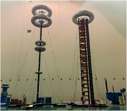
FIGURE 1. 6000kV impulse generator and impulse divider.
2.2 ±800kV high-end converter transformer
As the benchmark for high-end manufacturing in the power manufacturing industry, ±800kV high-end converter transformers feature complex technology and design, and high manufacturing difficulty. The technical parameters of converter transformer in the test is listed in Table 1.
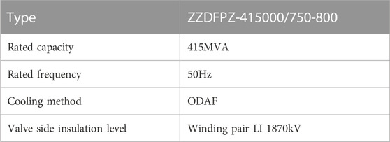
TABLE 1. Technical parameters of converter transformer.
3 Simulation model building
3.1 Equivalent circuit of lightning impulse voltage
The equivalent circuit of lightning impulse voltage is illustrated in Figure 2, where C1 is the impulse capacitance, C2 the load capacitance, L the loop inductor, S the synchronous discharge spherical gap,
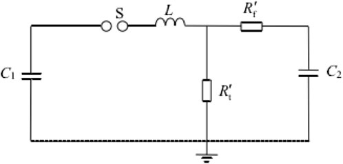
FIGURE 2. Equivalent circuit of lightning impulse voltage.
According to the equivalent circuit of lightning impulse voltage, the RLC loop differential equation is formulated and solved:
Where T1 is the wavehead time, T2 the half-peak time, C1 the impulse capacitance, and C2 is the load capacitance.
3.2 Simulation model
Simulative study and analysis was made to the lightning impulse full-wave test on the valve side of the ±800kV converter transformer. A simulation model is established according to the above lightning impulse equivalent circuit, and the converter transformer circuit model achieved equivalence through a model with capacitance and inductance in parallel (Shiquan, 1994a; Yuren et al., 2003; Xuemin, 2013), where the capacitance is 5000pF and the inductance 13mH. The test loop’s load capacitance includes: 1) test transformer’s inlet capacitance 5000pF; 2) voltage divider’s capacitance 300pF; 3) voltage divider and equalizer hood to ground capacitance 650pF; 4) impulse generator and equalizer’s capacitance to ground 350pF; 5) interception device’s capacitance 400pF; 6) interception device’s capacitance to ground 200pF. The test loop’s inductance includes: 1) the inductance of the impulse voltage generator body, which operates at 5μH per stage, 2 in parallel and 10 in series, with the calculation value of 50μH, and 2) high-voltage lead inductance, based on 1 μH/m (Shiquan, 1994b), is 14μH. The voltage divider resistor is 450Ω.
The simulation model is established under the original parameters of the impulse voltage generator, in which the input voltage is U1, the output voltage U0, the generator efficiency η, the wavefront time T1, the half-peak time T2, and the relative overshoot amplitude β. Table 2 describes the parameter settings as follows.
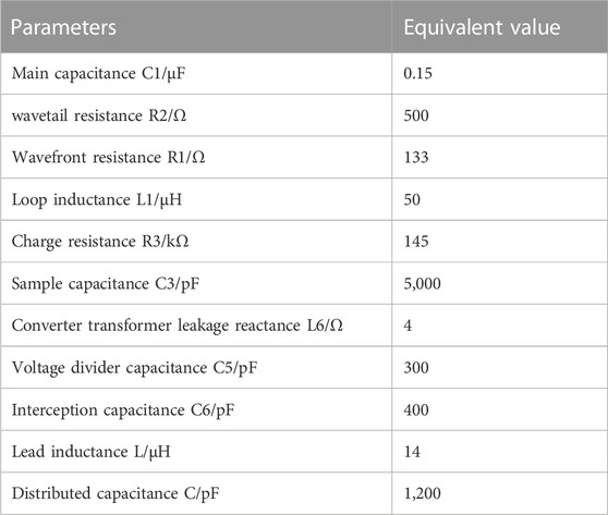
TABLE 2. ±800kV simulation parameters of lightning impulse test on valve side of converter transformer.
The simulation waveform is shown in Figure 3. The simulation results are U1 = 200kV, U0 = 1869.3kV, T1 = 1.73 μs, T2 = 23.74 μs, η = 93.46 and β = 2.47.
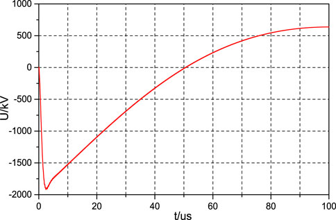
FIGURE 3. Simulation waveform of LI test on valve side of converter transformer under original parameter.
According to the specifications in IEC 60076-3 2013 (International Electrotechnical Commission, 2013) Power transformers—Part 3:Insulation levels, dielectric tests and external clearances in air and IEC 60060-1 2010 (International Electrotechnical Commission, 2010) High-voltage test techniques—Part 1: General definitions and test requirements, the “standard lightning impulse full wave: 1.2 μs ± 30%/50 μs ± 20%, for transformers with Um ≤ 800kV, the wavefront time should not exceed 2.5 μs. It can be seen that if no measures are taken, the wavefront time of the lightning impulse full-wave test on the valve side of the converter transformer meets the requirements. And the half-peak time does not meet the requirements. Therefore, a certain wave regulation method is required so that the impulse voltage generator can meet the requirements of the lightning full-wave test standard on the converter valve side.
4 Single-mode modulation analysis
4.1 Increase the wavetail resistance
It can be seen from Eq. 2 that under the condition of determining the impulse capacitance and load capacitance, increasing the half-peak time can be achieved by increasing the wavetail resistance. In order to make full use of the laboratory wave modulation resistance and reflect the change of waveform with wavetail resistance, we considered increasing the wavetail resistance by 10 times to 5000Ω, and further simulation of wavetail resistance at 8000Ω, 10000Ω, and U1 = 190kV while other parameters remain unchanged.
The waveform of the simulation results is shown in Figure 4, with a slight increase in half-peak time as the wavetail resistance increases.
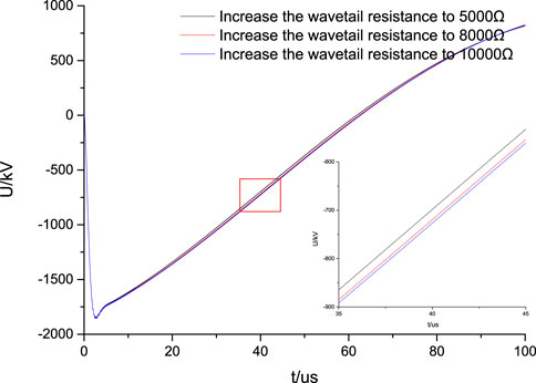
FIGURE 4. LI simulation waveform when the wavetail resistance increases.
The waveform parameters are shown in Table 3, it can be seen that when the wave-tail resistance increases to 5000Ω, 8000Ω, and 10000Ω, the wavefront time of the lightning impulse full-wave test on the valve side of the converter transformer meets the requirements, and the half-peak time increases significantly, but it still does not meet the standard requirements.
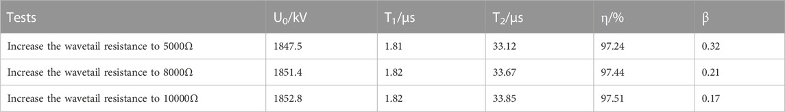
TABLE 3. Statistics of simulation results when the wavetail resistance increases.
4.2 Increasing the load capacitance
It can be seen from Eq. 2 that under the condition of a fixed impulse capacitance, increasing the load capacitance will increase the half-peak time. So the half-peak time requirement is met by increasing the load capacitance during the simulation. According to the existing load capacitance and wave regulation requirements of the laboratory, the load capacitance of 3000pF, 6000pF and 9000pF are added respectively in the simulation.
The simulation waveform of the increased load capacitance is shown in Figure 5 as the load capacitance increases, the half-peak time increases significantly, but the wavefront time also increases.
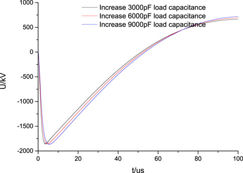
FIGURE 5. LI simulation waveform when load capacitance is added.
The waveform parameters are shown in Table 4. When the load capacitance increases by 3000pF, both the wavefront time and half-peak time increase. The wavefront time meets the requirements but is close to the limit, and the half-peak time increases but still does not meet the standard requirements. When the load capacitance increases by 6000pF and 9000pF, both the wavefront time and the half-peak time increase, but neither meets the standard requirements.
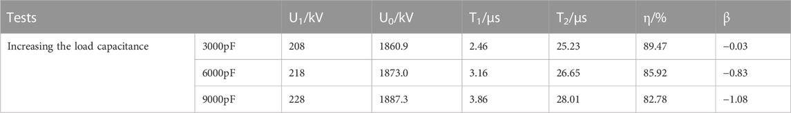
TABLE 4. Statistics of simulation results when load capacitance is added.
4.3 Connecting wavehead resistance with inductor in parallel
According to IEC 60076-4 2002 Appendix A: Waveform control principle (International Electrotechnical Commission, 2002), by connecting the inductors in parallel with the wavehead resistance, the half-peak time can be increased, and it will be greater than the half-peak time generated when the impulse voltage generator is used alone. In the simulation test described herein, the 1mH, 1.5mH, and 2mH inductors are connected in parallel with the wavehead resistance.
The simulation waveform for the parallel connection of wavehead resistor with inductance is shown in Figure 6. With the parallel inductance value increases, the half-peak time decreases.
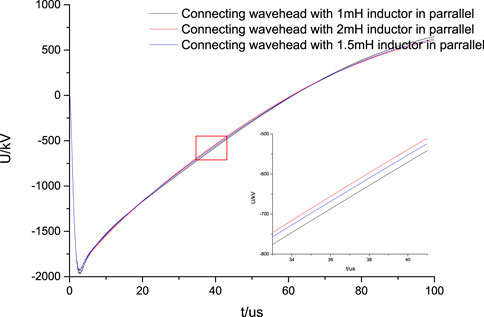
FIGURE 6. LI simulation waveform with inductor in parallel.
The waveform parameters are shown in Table 5, from which it can be seen that the inductance of 1–2mH in parallel with the wave head can meet the requirements of the wavefront time, and the half-peak time is increased but does not meet the standard requirements.
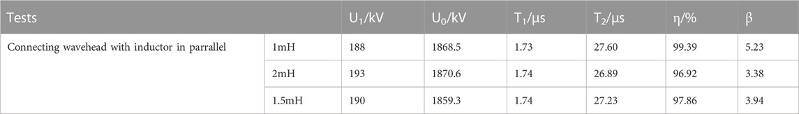
TABLE 5. Statistics of simulation results with inductor in parallel.
4.4 Results analysis
Statistical analysis of the above simulation results shows that, under the original parameter conditions, the wavefront time meets the requirements, but the half-peak time does not meet the requirements. After increasing the wavetail resistance to 5000Ω, 8000Ω, and 10000Ω, the half-peak time increases by 39.5%, 41.8%, and 42.6% respectively but still does not meet the requirements, and the increase of half-peak time shows a saturation trend with the increase of wavetail resistance. After increasing the load capacitance by 3000pF, 6000pF, and 9000pF, the half-peak time increased significantly by 6.3%, 12.3%, and 18.0% respectively, but the wave front time increased by 42.2%, 82.7%, and 123.1%, respectively, meanwhile, the trend of the increase of wave front time and half-peak time slowed down slightly with the increase of load capacitance, but the half-peak time still does not meet the requirements, and the wavefront time is too high to meet the requirements with the further increase of the capacitance. When the wave head is connected in parallel with 1–2mH inductors, with the increase of parallel inductance, the increase degree of half-peak time decreases, which is 16.3%, 14.7%, and 13.3% respectively, and the wavefront time is almost unchanged, the wavefront time meets the requirements, but the half-peak time does not meet the requirements. Therefore, we consider a combination of multiple modulation methods to make the waveform meet the standard requirements.
As can be seen from Figure 7, increases in wavetail resistance, load capacitance, and parallel inductance of wave head resistance can increase the half-peak time, and the half-peak time increases with the increase of the load capacitance and wavetail resistance, and decreases with the increase of the paralleled inductance. At the same time, the increase of load capacitance obviously causes the increase of wavefront time and cost higher, which the change of wavetail resistance and paralleled inductance has little effect on the wavefront time. Therefore, the combined wave modulation method considers increasing the wavetail resistance while increasing the wave head resistance.
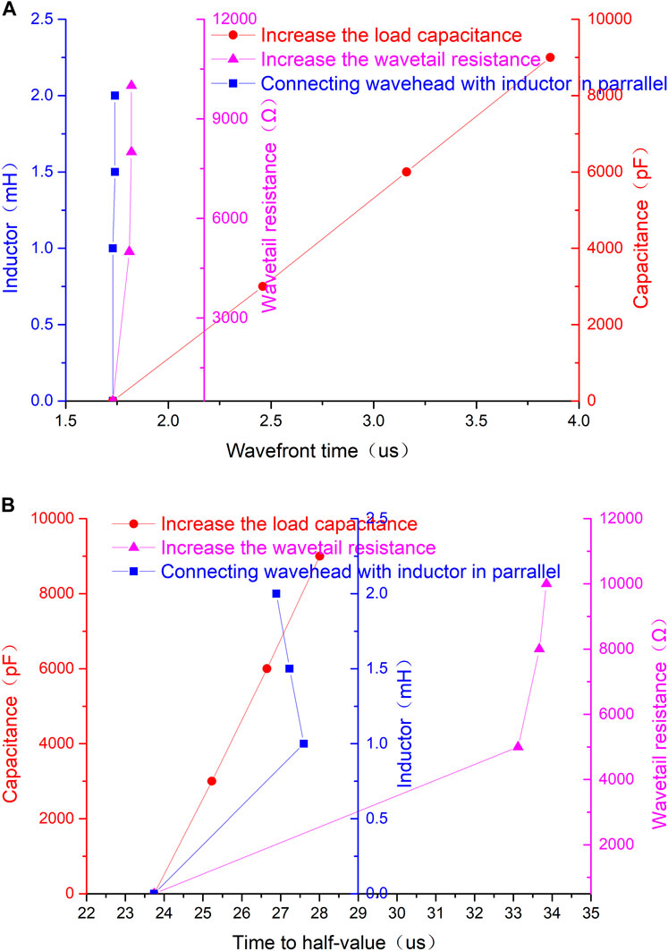
FIGURE 7. Influence of single waveform adjustment mode on waveform.
5 Combinatorial modulation analysis
Based on the existing impulse voltage generator and wave regulation components, we try to apply wave regulation methods that are easy to implement as much as possible to meet the waveform requirements of the lightning impulse full-wave test on the valve side of the ±800kV converter transformer.
According to the simulation results of the single modulation mode, it can be seen that the increase of the half-peak time through a single modulation method is limited, so the combined modulation method is considered. The combined wave modulation method intends to increase the parallel inductance of the wave head resistance while increasing the wavetail resistance. The effect on increasing the half-peak time declines with the increase of the wave head parallel inductance value, so the wave head parallel inductance value is set to be 1mH. Increasing the wavetail resistance can effectively increase the half-peak time, but as the wavetail resistance continues increasing, the half-peak time increases to a stable value. So, the wavetail resistance is determined to be 8000Ω based on a comprehensive consideration of the field wave modulation resistance elements and the wave modulation effect.
With the input voltage U1 = 180kV, and the simulation results of U0 = 1859.7kV, T1 = 1.82 μs, T2 = 42.28 μs, η = 103.32, = 3.72, the simulation waveform is shown in Figure 8. Both the wavefront time and half-peak time can meet the standard requirements, and the efficiency of the generator is significantly increased.
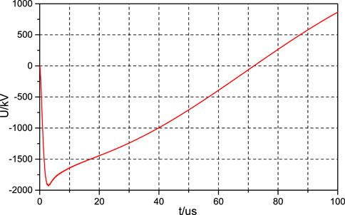
FIGURE 8. Simulation waveform of LI in combined modulated wave mode.
6 Application tests
An optimally configured impulse voltage generator is applied to complete the lightning impulse test on the valve side of the ±800kV converter transformer (ZZDFPZ-415000/750-800). The test ambient temperature is 18°C, the relative humidity is 46%, and the test site is shown in Figure 9. The waveform recorded by Impulse Analysing System of Haefely Test AG in Figure 10.

FIGURE 9. LI test site on valve side of converter transformer.

FIGURE 10. Field test waveform diagram.
The test data are shown in Table 6. Among them, the lightning impulse voltage wavefront time is effectively controlled within 2.5 μs, the half-peak time meets the requirements of 50 μs ± 20%, and the waveform parameters meet the needs of engineering applications, and the converter transformer is in service at the ±800kV Qingnan converter station without any operation abnormalities for 3 years.
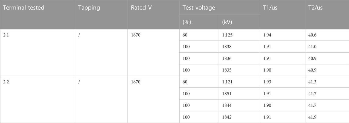
TABLE 6. Valve side LI test data.
7 Conclusion
In this paper, the simulation analysis compares the optimization methods of increasing the wavetail resistance, increasing different load capacitors, and connecting the wavehead resistance with different inductors in parallel, completes the test verification, and obtains the following conclusions:
(1) Only increasing the wavetail resistance can effectively increase the half-peak time. But as the wavetail resistance continues to increase, the increase of half peak time tends to be saturated.
(2) Only increasing the load capacitance can increase the half-peak time. The half-peak time increases with the increase of the load capacitance, but increasing the load capacitance will lead to a more significant increase in the wavefront time.
(3) The wavehead resistance’s parallel connection with the inductance alone can increase the half-peak time. But with the increase of the paralleled inductance value, the increasing degree of half-peak time gradually decreases, and the wavefront time is almost unchanged.
(4) The single wave regulation mode has limited wave regulation ability. The method of wave head parallel inductance combined with increasing wavetail resistance meets the requirements of lightning full-wave test waveform and the needs of project applications.
Data availability statement
The original contributions presented in the study are included in the article/Supplementary Material, further inquiries can be directed to the corresponding author.
Author contributions
LJ, SW, and JK, are responsible for methodology and writing original-draft, XaY, XuY, ZB, and YoZ are responsible for obtaining the experimental data and data curation. YiZ is responsible for review and editing. All authors contributed to the article and approved the submitted version.
Funding
The authors declare that this study received funding from the Science and Technology Program of the State Grid Qinghai Electric Power Company under “Research on Key Technology of External insulation of high altitude ±800kV (±1100kV) DC UHV transmission and transformation equipment (522807210005)”.
Conflict of interest
Authors LJ, SW, XaY, YiZ and ZB were empolyed by State Grid Qinghai Electric Power Company. JK was empolyed by Haibei Electric Power Company, State Grid Qinghai Electric Power Company. XuY was empolyed by China Electric Power Research Institute Co., Ltd. YoZ was empolyed by State Grid Qinghai Electric Power Company.
Publisher’s note
All claims expressed in this article are solely those of the authors and do not necessarily represent those of their affiliated organizations, or those of the publisher, the editors and the reviewers. Any product that may be evaluated in this article, or claim that may be made by its manufacturer, is not guaranteed or endorsed by the publisher.
References
Boxue, D., Wenbo, Z., Jin, L., and Jinpeng, J. (2019). Research status of oil-paper insulation for valve side bushing of converter trans-former. Trans. China Electrotech. Soc. 34 (6), 186–195. doi:10.19595/j.cnki.1000-6753.tces.180268
Fengfeng, L., and Nengling, T. (2007). Operational analysis of converter transformers of DC transmission systems of SGCC. East China Eleceric Power 35 (1), 58–60.
Guangfan, L., Weiming, L., Qingfeng, L., Yujian, D., and Lin, S. (2008). Voltage output performance of 7200 kV/480kJ impulse voltage generator. Proc. CSEE 28 (25), 1–7.
Guogang, W., Juntao, Z., and Feng, L. (2010). Research on test method of ±800kV converter transformer. Transformer 47 (08), 35–40.
Haoyang, W., Wei, S., Zhengcai, F., and Jian, C. (2009). Investigation of load impact on output capability of impulse voltage generator. High. Volt. Appar. 45 (5), 92–95.
Haoyang, W. (2009). Investigation of the load impact on the out-put capability and the synchronization of impulse voltage generators. Shanghai, China: Shanghai Jiao Tong University.
International Electrotechnical Commission (2010). “High-voltage test techniques part 1: general definitions and test requirements,” in IEC Standard 60060-1, 2010.
International Electrotechnical Commission (2002). “Power transformers-Part 4: Guide to the lightning impulse and switching impulse testing-Power transformers and reactors,” in IEC Standard 60076-4, 2002.
International Electrotechnical Commission (2013). “Shunt reactors Dielectric test and external clearances in air,” in IEC Standard 60076-3, 2013.
Jianxin, Z., Fangfang, Z., and Heng, S. (2015). Debugging of lightning impulse voltage waveform under high voltage large capacitive load. Electrotech. Electr. (04), 27–30.
Kaigui, X., Huaidong, M., Bo, H., Kan, C., and Chunyan, L. (2011). Reliability evaluation of converter transformer system in HVDC transmission system based on markov state space graph algorithm. Power Syst. Technol. 35 (9), 71–78. doi:10.13335/j.1000-3673.pst.2011.09.019
Qiying, L., Peng, L., Tao, Z., Zheng, Z., Xiangzhong, W., Keliang, L., et al. (2018). Comparison and optimization of feasible schemes for on-site assembly of ±1100kVconverter transformer. High. Volt. Appar. 54, 27–33. doi:10.13296/j.1001-1609.hva.2018.10.004
Shengxia, D., Shaokui, Y., and Rui, T. (2021). Study on debugging of lighting impulse voltage waveform for UHV transformer based on the fourth order circuit model. Insulators Surge Arresters (06), 102–107.
Shiquan, Z. (1994a). Estimation of inductor of impulse voltage generator and experiment circuit. Transformer 31 (3), 27–29.
Shiquan, Z. (1994b). Estimation of stray capacitance of impulse voltage generator. J. Transform. 31 (10), 21–24.
Taoxi, Z., Min, Z., Weiming, G., and Jie, H. (2010). The problems of protection systems of converter transformers used in HVDC transmission projects in CSG. Power Syst. Prot. Control 38 (13), 140–143.
Xiaodong, H., and Yadong, Z. (2002). Converter transformer used for HVDC transmission. High. Volt. Appar. 38 (3), 5–6.
Xin, Z., Peigeng, L., Kuang, X., Yun, F., Jing, P., Jiawei, L., et al. (2011). Insulation structure and experiment of UHV converter transformer. High. Volt. Appar. 47 (5), 11–15. doi:10.13296/j.1001-1609.hva.2011.05.003
Xuecheng, Z., Jinhua, T., Wanyu, N., Liangsheng, P., and Can, L. (2012). Bush-ings design of converter transformer’s valve side of UH-VDC transmission project. High. Volt. Eng. 38 (2), 393–399.
Xuemin, L. (2013). Research on wave-affecting factor of transformer impulse tests. North China Electric Power University.
Xuexian, C., and Youbin, Z. (1997). Measures to improve the load capacity of impulse voltage generator. High. Volt. Appar. 01, 17–19.
Xuyun, Z., Gang, Z., Wei, S., and Wenzhen, C. (2002). Analysis of the capacitive load ability of 3600 kV serial impulse generator. High. Volt. Eng. 28 (8), 14–16. doi:10.13336/j.1003-6520.hve.2002.08.006
Yang, L. (2010). Key technologies for field installation of converter transformers in the Yunnan-Guangzhou ±800 kV UHVD C transmission project. Electr. Power Constr. 31 (7), 59–62.
Yanjie, L., Enke, Y., and Guozhi, C. (2017). Parameter control of lightning impulse voltage test waveform for DC power cable based on optimization model. Trans. CHINA Electrotech. Soc. 32 (17), 225–234.
Youbin, Z., Zheng, L., and Jiansheng, W. (1999). Analy-sis and improvement of load characteristics and its waveform to lighting impulse voltage generator. High. Volt. Appar. 35 (1), 19–23.
Yuren, Z., Changyu, C., and Changchang, W. (2003). High voltage test techniques. Beijing, China: Tsinghua University Press.
Keywords: ±800kV converter transformer, lightning impulse test, time to half-value, front time, high altitude
Citation: Jiang L, Wang S, Kang J, Yang X, Yao X, Zhang Y, Bao Z and Zhang Y (2023) Study on debugging of lightning impulse voltage waveform for large capacity ±800kV converter transformer in high altitude area. Front. Energy Res. 11:1226519. doi: 10.3389/fenrg.2023.1226519
Received: 21 May 2023; Accepted: 12 September 2023;
Published: 13 October 2023.
Edited by:
George Tsekouras, University of West Attica, GreeceReviewed by:
Vassiliki T. Kontargyri, National Technical University of Athens, GreeceIoannis Gonos, National Technical University of Athens, Greece
Copyright © 2023 Jiang, Wang, Kang, Yang, Yao, Zhang, Bao and Zhang. This is an open-access article distributed under the terms of the Creative Commons Attribution License (CC BY). The use, distribution or reproduction in other forums is permitted, provided the original author(s) and the copyright owner(s) are credited and that the original publication in this journal is cited, in accordance with accepted academic practice. No use, distribution or reproduction is permitted which does not comply with these terms.
*Correspondence: Yitao Zhang, MTMyNjMzMzEzMDNAMTYzLmNvbQ==