 Min Rui
 Tianming Chen
- China Guangdong Nuclear Research Institute Co., Ltd., Shenzhen, China
Helical tubes are widely used in nuclear plants, heat recovery process, refrigeration technology, etc. It is obtained the helical tubes dry out point prediction model in accordance with the experimental conditions by numerical simulation. The article is based on the physical model of the liquid membrane in the helical tube before dry out happened, establishing the analytical process of liquid film development in helical tube. The physical mechanism, thermo-hydraulic parameters that affect liquid film crushing are analyzed. The dry out point of helical tubes is predicted based on the experimental data. The result shows that the geometrical, thermo-hydraulic parameters of helical tube will affect the occurrence of the dry out point, the development process of liquid film before evaporation of spiral tube is obtained. The prediction model of dry out point is fitted to experimental data and the predicted results of evaporation point can be used to optimize during the engineering design.
1 Introduction
The evaporation phenomenon of helical tube Once Through Steam generator (OTSG) is different from that of straight tube. The centrifugal force of spiral tube has obvious effect on liquid film aggregation, and the heat equilibrium vapor content at the evaporation point is higher (Guo et al., 1998; Hwang et al., 2014). After evaporation, the heat transfer of capacity straight tube is stronger and the heat transfer efficiency per unit volume is higher, so it is widely used in PWR (Pressurized Water Reactor). Especially in integrated small reactors or marine small reactors. At the same time, the secondary flow caused by centrifugal force exists in the spiral pipe, which makes the flow more complicated than that in the straight pipe (Dean et al., 1927; Mori et al., 1965; Mori et al., 1967).
In the helical tube, the drying phenomenon is caused by the deterioration of heat transfer due to the failure of annular flow liquid film to maintain and rupture. The drying phenomenon has a clear demarcation point, and the local point heat transfer deterioration and wall temperature soaring will occur at the drying position, which will be used as the landmark point for the transition from two-phase heat transfer to liquid-deficient heat transfer in the spiral tube. There is a partial dry section in which one part of the wall is covered by liquid film and the other part is dry. There are two special physical quantities in the drying of spiral pipe, one is the drying starting point dryness, that is, the thermodynamic void fraction corresponding to the first drying point, and the other is the complete drying point dryness, that is, the thermodynamic void fraction corresponding to the complete drying of spiral pipe in the circumferential direction. Due to the interaction of gravity and centrifugalforce, the drying phenomenon of fluid in spiral pipe is different from that in vertical pipe. The biggest characteristic of drying phenomenon in spiral pipe is the existence of partial drying section. In the dry section, one part of the interface circumference is covered by liquid film, and the other part of the surface dries up. Therefore, in the drying phenomenon of spiral pipes, the dryness of the starting point and the complete drying point is often the most concerned. Some parameters, such as pressure, mass flow rate, heat flux, inner diameter and curvature diameter of spiral pipe, have significant influence on the drying phenomenon in helical part (Mori et al., 1965; Mori et al., 1967; Hewitt et al., 1992).
The dry point of spiral pipe is mainly studied on the basis of straight pipe, and the mature empirical relations (Bi et al., 1996; Niu et al., 2018) of critical vapor fraction of straight pipe are mainly related to mass flow rate, pressure and other parameters. Existing researchers have carried out a large number of experimental studies on the drying phenomenon in spiral pipes (Carver et al., 1964; Naitoh et al., 1974; Jayanti et al., 1990; Chung et al., 2002; Elsayed et al., 2012; Chung et al., 2014; Santini et al., 2014). They found that the dryness in the spiral tube did not happen suddenly at a certain point, but gradually transitioned from the starting point of dryness to complete dryness, and there was a partial dryness section. Indicators of dryness in spiral pipes usually include fluid dryness at the starting point of dryness, fluid dryness at the complete drying point and the position of the starting point of dryness at the circumference. Because of the combined action of centrifugal force and gravity, the fluid flow in spiral pipe is quite different from that in dry vicinity of vertical pipe. Due to the centrifugal force, the droplet settling effect on the outer side of the circumference will be enhanced, but there is a velocity difference on the cross section and a pressure difference inside and outside the interface, which will lead to the occurrence of secondary flow in the spiral pipe. The secondary flow mainly shows the phenomenon that the fluid from the outer side of the circumference flows to the inner wall. At the same time, gravity will also cause the liquid to accumulate in the lower circumference.
Chung and Bae (Chung et al., 2014) compares the results of the dry point experiment with the results of Chen relation (Chen et al., 1979), modified Schrock-Grossman relation (Nariai et al., 1982) and Steiner-Taborek relation (Steiner et al., 1992). The results show that Chen relation can be used to calculate the boiling heat transfer coefficient in low heat transfer region, but in high heat transfer region, the calculated value is obviously lower than the experimental value; The calculated value of modified Schrock-Grossman relation is quite different from the experimental value; Steiner-Taborek equation can reasonably predict boiling heat transfer coefficient.
Jayanti and Berthoud (Jayanti et al., 1990) studied the fluid flow phenomenon after Steam generator secondary side drying of spiral pipe, and pointed out that unlike the mechanism of drying point in vertical pipe, the fluid in spiral pipe will not directly change from annular flow to dispersion flow at the drying point in vertical pipe due to the influence of centrifugal force and gravity, but will undergo a process from drying point to partial drying and finally to complete drying. The drying phenomenon in spiral pipe is mainly affected by four phenomena.
1) The liquid in the wall liquid film is entrained by steam;
2) The liquid droplets in the steam settle on the liquid film on the wall surface;
3) Evaporation of the liquid film due to heat;
4) Dragging of the liquid film by the secondary flow.
The fitting formula of drying point corresponding to dryness is as follows, and compared with the experimental results of Centre’d Etudes Nucleaires de Grenoble (CENG) (Jayanti et al., 1990).
Chung and Sa (Chung et al., 2002) made an experimental study on the drying-up phenomenon in spiral pipe, and pointed out that the strength of centrifugal force and gravity in spiral pipe affects the local position of drying-up point. The boiling heat transfer coefficients of fluids in spiral tubes with small diameter (inner diameter less than 3 mm) were studied experimentally by Ahmed M. Elsayed and Raya K. AL-Dadah (Elsayed et al., 2012). According to the experimental results, the effects of inlet mass velocity, tube wall heat flux, spiral tube diameter and spiral tube curvature diameter on boiling heat transfer coefficient were analyzed. Santini and. Cioncolini et al. (Santini et al., 2014). Conducted a large-scale experimental bench study on Steam generator drying phenomenon of spiral pipe (Carelli et al., 2004), and analyzed the influence of inlet mass velocity and gauge pressure of spiral pipe on void fraction at drying starting point and complete drying point. Experiments show that in the case of low mass flow and low pressure, the starting point of drying mostly occurs outside the top of the circumference, which is due to the dominance of gravity relative to centrifugal force in this case. In the case of high flow velocity, the starting point of drying mostly occurs at the top and bottom, because the entrainment and settling of droplets are stronger than other effects in this case.
Jayakumar and Mahajani (Jayakumar et al., 2002) used Computational Fluid Dynamics (CFD) software FLUENT to model the thermo-hydraulic phenomenon of air-water heat transfer flow in spiral tubes. The model uses Euler-Euler fluid to model air and water, and analyzes the effect of coiled tube aggregate parameters on thermo-hydraulic parameters and heat transfer process. Marco Colombo and Antonio Cammi (Colombo et al., 2015) used CFD to study the air-water mixed flow in a helical tube. The purpose is to obtain the accurate cavitation fraction and frictional pressure drop along the helical tube, and to study the influence of centrifugal force on the two-phase fluid distribution in the helical tube. The data obtained by Analog will be compared with the experimental data of Aaagawa et al. (Akagawa et al., 1971). The effects of bubble size and wall boundary conditions on the flow are also compared and analyzed in the model.
The research status of the spiral tube evaporation drying point has been described above, and the evaporation drying phenomenon of spiral tube has attracted the attention of many researchers in the past few decades. The drying point of spiral tube affects the scaling and local heat exchange performance of spiral tube, and the occurrence of drying point will lead to the deterioration of local heat exchange of spiral tube and bring greater thermal stress, which ultimately affects the safety performance of spiral tube. If the pipe deteriorates due to the evaporation point of the spiral pipe, and eventually a breach accident occurs, it will lead to a radioactive leakage accident. Therefore, by studying the spiral tube evaporation point and modifying the pipeline design, the safety of the reactor can be improved, and the study of the spiral pipe evaporation point is necessary.
In this paper, based on the phase change model of the drying principle of liquid film before evaporation point, the physical model is established, and the thermo-hydraulic model is used to analyze and the stress of liquid film development process is obtained. The principle of liquid film breakage during drying is explained through the development process of liquid film, and the main physical parameters affecting the evaporation phenomenon of spiral pipe are obtained. Based on the analysis of the physical model, combined with the experimental data results of the spiral tube, the calculation formula for predicting the evaporation point of the spiral tube is obtained, which can be used to optimize the numerical calculation model of the spiral tube in the future.
2 Model and analysis
2.1 Physical analysis of liquid film
For the force analysis of spiral pipe, including centrifugal force
Figure 1 shows the velocity behavior on the liquid film of helical tubes. Under the combined action of centrifugal force, buoyancy and gravity, the gas phase in the two-phase region gathers inside the tube and forms a gas group. In this process, bubbles are easier to collide and aggregate to form large bubbles. However, due to the lateral flow of the spiral tube and the scouring of the vapor-liquid interface by the secondary vortex, bubbles will break up and gradually form a stable spiral tube bubble flow.
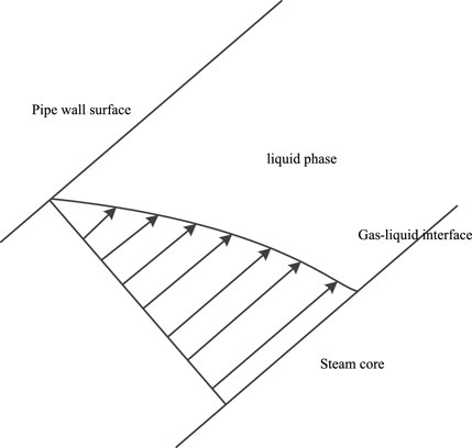
FIGURE 1. Velocity gradient on the liquid film.
With the increase of gas phase, the impact frequency of small bubbles increases, and the bubbles gradually form large bubbles with discrete broken small bubbles around them. Because of the expansion of large bubbles, the size of gas-liquid interface increases, the curvature of bubbles increases, and the surface tension of maintaining bubbles gradually decreases. With the continuous aggregation of bubbles, they occupy the main space in the tube and gradually form a stable hydrodynamic state.
With the increase of the vapor content, the gas phase gathers continuously to form long and narrow bubbles, which elongate continuously in the inner side of the pipe and gradually form annular flow. Because the liquid film on the wall becomes thinner and thinner, the flow shear force on the wall will change, which will make the liquid film become unstable gradually. At the end of annular flow, because of the uneven distribution of liquid film thickness in the radial direction of spiral pipe, the liquid film thickness on the inner wall is lower, and the flow shear force acting on local position is greater. When the surface tension cannot maintain the liquid film, local liquid film breaks, where is, evaporation occurs.
As shown in Figure 2, the evaporation point analysis of the spiral pipe shows that the gas phase gathers above the pipe wall, and the inclination angle of the spiral pipe is. With the heating, the liquid film thickness H at the thinnest position of the liquid film in the annular flow gradually decreases, so only the adjacent area of the thinnest position of the liquid film is studied in the research process.
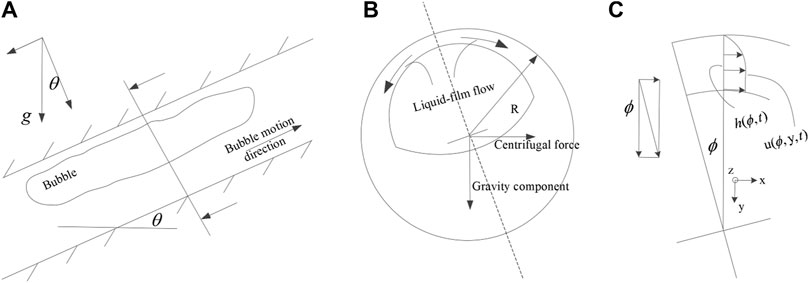
FIGURE 2. The stress on the liquid film of helical tube: (A) Stress on the axial interface. (B) Stress on the radial interface. (C) The coordinate system established on the liquid film.
For the force analysis of unit fluid volume on the liquid film, as shown in Figure 2B, the gravity component of the liquid film in the helical pipe section
For quantitative analysis, it is defined as the liquid film thickness at different positions, which are the flow velocities in azimuth direction, radial direction and axial direction on the liquid film respectively. In order to study the variation of liquid film thickness at the local evaporation position in the spiral pipe, it is necessary to establish a flow model for the liquid film flow at the end of annular flow. First, the assumptions are as follows.
1) The position of the control body is the thinnest position in the radial direction of the tube which is determined only by the centrifugal force and gravity of the spiral tube.
2) The dimensions of the control body in axial direction and azimuth direction are very small relative to the tube radius R.
3) Liquid film thickness H is far less than tube radius R, while ignoring the fluctuation of liquid film surface, axial velocity is stable.
4) In the control body, except for the directional mass flow, other phase transition sources and heat transfer on the wall make the saturated liquid evaporate and phase change, and the liquid film becomes thinner.
2.2 Film model analysis
Based on the above assumptions, it can be considered that the thickness of the liquid film at the research site is very thin relative to the pipe diameter and the curvature of the liquid film is very small. Referring to the existing analysis method for studying the change process of the liquid film in straight pipes (Garcia et al., 2016) the Cartesian coordinate system established on the local liquid film at the research point can be obtained, and the Navier-Stokes equation in the upper direction of the liquid film is as follows:
The angle of deviation from the thinnest liquid film position in the axial direction is, and the force per unit volume on the liquid film is as follows:
In the analysis of thin liquid film velocity of Taylor bubble in inclined straight tube, the velocity v in radial direction can be ignored, except for other convection terms, which can be simplified as:
For Z direction, the boundary conditions of no slip on the wall and stable liquid phase velocity on the liquid film surface are adopted:
Solution as:
In the process of heating the wall, under a certain heating power, the heat is completely transferred to the saturated liquid to undergo phase change, and the liquid film evaporates continuously, which makes the thickness of the liquid film gradually decrease. Therefore, under the condition of constant heating power, the continuity equation of the liquid film is analyzed:
The right side of the equation in the relation is the source term, which represents the mass change rate of liquid evaporation caused by the heat flux per unit heating area, and is constant under the condition of constant heat flux. On the left is the time rate of change of the mass of the control body and the convection term in two directions, which indicates the rate of change of the mass of the control body. By simplifying, you can get:
At the position where the thinnest liquid film is analyzed, the convection term is analyzed as follows:
At the thinnest position of the liquid film, that is, when it tends to 0, the thickness of the liquid film can be considered to be uniform:
Therefore, the term with liquid film gradient in convection term is ignored, and the functional equation describing the change of liquid film thickness with time is obtained:
Where:
The first-order differential equation (Hurlburt et al., 2000) is solved to analyze the change of liquid film thickness at the thinnest position of annular flow, and the development of liquid film within one second is calculated with 0.1 mm as the initial value of the top liquid film thickness h (x = 0 position). The function is called in MATLAB to solve the differential equation with Runge-Kutta algorithm, and the change of liquid film at the top of annular flow with time is obtained.
The calculation results are shown in Figure 3. The liquid film thickness will continue to decrease with heating, but with the thinning of the liquid film, the flow shear force described in Figure 2B will increase with the decrease of the liquid film thickness, which will affect the instability of the liquid film. When the flow shear force acting on the local position of the liquid film exceeds the surface tension maintaining the liquid film, the liquid film will break at this position.
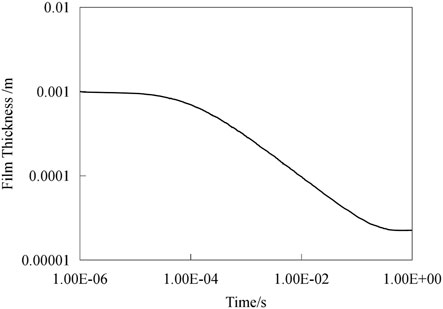
FIGURE 3. The variation of film thickness (m) with time(s).
In the process of liquid film change, the ratio of flow shear force acting on liquid film surface to surface tension maintaining liquid surface stability is as follows:
Among them, the axial element of the liquid film control body is the mainstream speed. As the thickness of the liquid film becomes smaller and larger, the flow shear force acting on the surface of the liquid film is greater than the surface tension maintaining the liquid film, and the liquid film will break. The surface tension coefficient is related to the liquid film temperature, while the liquid film in annular flow is at saturation temperature, which is affected by the system pressure. The flow shear force on the surface of liquid film is related to the flow velocity and heating power. These parameters affect the development process of liquid film and the occurrence of evaporation phenomenon, that is, the critical vapor fraction is related to the following parameters:
Among them:
Based on the above analysis, the starting position of spiral pipe drying is as follows:
For the working conditions with variable heat Flux, such as liquid-liquid convection heat transfer and other heating working conditions, the integral form is as follows:
3 Prediction of evaporation point of helical pipe
Based on the theoretical analysis of evaporation phenomenon in spiral tube Steam generator, the phase transition experiment of spiral tube heating tube was carried out. The experimental object is a uniform spiral pipe with different ratio of inner diameter to Coil diameter. The phase change of liquid in the pipe is caused by uniform electric heating along the axial direction of the pipe. Control the inlet feed water flow, inlet steam content, pressure and other parameters to adjust the experimental conditions.
The experimental results show that the liquid in the helical tube changes from saturated liquid phase to superheated steam with the heating, and the temperature in the tube is at the saturated temperature corresponding to the pressure in the tube in the two-phase region. With the evaporation, the saturated liquid phase in the liquid-deficient region changes to evaporate. Through the Thermocouple set at different axial positions of the tube, it can be found that the soaring phenomenon will take place first at the local position, that is, the local evaporation point will take place first. The starting point of temperature soaring and the peak position of heat transfer coefficient are used as the judgment basis of evaporation point position of spiral tube.
After obtaining the position of evaporation point of spiral tube by experimental data, combined with the theoretical analysis of local evaporation point of spiral tube, the evaporation point is predicted. The location of local evaporation of spiral tube is affected by the geometric parameters of spiral tube, system pressure, mass flow rate and heating heat flux.
Using the steam content of heat balance as the judgment Standard of evaporation drying point, the mature calculation model of steam content of heating straight pipe facing the street is:
Based on the results of the axial average heat transfer coefficient obtained from the experimental treatment, the position where the Contact heat transfer coefficient increases for three consecutive times is identified as the starting position of the evaporation point, and the modified results of the straight tube relational form are fitted. The specific results are as follows.
In Figure 4, the error between the 82 critical heat equilibrium vapor fractions of the experiment and the calculated heat equilibrium vapor fractions of the fitting results is within 10%. The results show that the predicted values of the evaporation point of the spiral pipe calculated by the fitting results are well matched with the experimental results. The fitting formula for calculating the critical heat equilibrium vapor fractions of the spiral pipe can be used to predict the evaporation point of the spiral pipe.
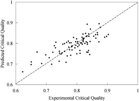
FIGURE 4. The fitting result of the dry out point.
On the basis of predicting the evaporation point of spiral tube, the heat transfer process of spiral tube can be further discussed in different areas, which is beneficial to the accurate prediction and numerical analysis of spiral tube heat transfer model. After adding the relationship fitting of the main physical parameters of the spiral pipe, the fitting results are better than those of the straight pipe, and the analysis method and Arguments process of the evaporation phenomenon of the spiral pipe are Validation.
4 Conclusion
In this paper, the main parameters affecting the evaporation point of spiral tube are discussed by thermo-hydraulic analysis of liquid film development before evaporation of spiral tube, and the evaporation point of spiral tube in data, is predicted. The main conclusions are as follows.
1) In this paper, the liquid film development model is used for the first time to analyze the occurrence phenomenon of spiral tube drying point, and the spiral tube evaporation model is innovatively derived from the physical model and mathematical model of liquid film evaporation process. The ideal model is used to simplify the development process of liquid film, and the analysis method and development process of liquid film in the tube are proposed, which provides ideas for similar analysis. Under the assumption that the heat flux density is fixed and the liquid film fluctuation and fold phenomenon are not considered, the surface tension and shear force of the liquid film are used as the main influencing factors affecting the occurrence of liquid film fragmentation The relationship between the location of the evaporation drying phenomenon and the main physical parameters is analyzed.
2) Combined with the experimental data of spiral pipe, the location of spiral pipe is predicted by the method of relation fitting.
3) The predicted results of evaporation point can be used to optimize the heat transfer relationship of spiral tubes in different zones.
Data availability statement
The original contributions presented in the study are included in the article/Supplementary material, further inquiries can be directed to the corresponding author.
Author contributions
MR and YiH contributed to conception. YM and YoH contributed to methodology. XZ, MZ, and TC organized the database and performed the statistical analysis. TC wrote the first draft of the manuscript. DJ and TC wrote sections of the manuscript. All authors contributed to the article and approved the submitted version.
Funding
This research was funded by National Natural Science Foundation of China (grant number U20B0211 and 52171085) and Department of Science and Technology of Guangdong Province (grant number 2017B020242001).
Conflict of interest
Authors MR, TC, MZ, XZ, YiH, DJ, YoH, and YM were employed by the China Guangdong Nuclear Research Institute Co., Ltd.
Publisher’s note
All claims expressed in this article are solely those of the authors and do not necessarily represent those of their affiliated organizations, or those of the publisher, the editors and the reviewers. Any product that may be evaluated in this article, or claim that may be made by its manufacturer, is not guaranteed or endorsed by the publisher.
References
Akagawa, B. K., Sakaguchi, T., and Ueda, M. (1971). Study on a gas-liquid two-phase flow in helically coiled tubes. JSME Int. J. B 14 (72), 564–571. doi:10.1299/jsme1958.14.564
Bi, Q. C., Chen, T. K., Tian, Y. S., and Chen, X. J. (1996). Study on critical heat flux of steam water two-phase flow coil tubes. J. Xi’an Jiaot. Univ. 5, 30–35.doi:10.1016/j.tsep.2021.101143
Carelli, M. D., Conway, L. E., Oriani, L., Petrovic, B., Lombardi, C. V., Ricotti, M. E., et al. (2004). The design and safety features of the IRIS reactor. Nucl. Eng. Des. 230, 151–167. doi:10.1016/j.nucengdes.2003.11.022
Carver, J. R., Kakarala, C. R., and Slotnik, J. S. (1964). Heat transfer in coiled tube with two-phase flow, Akron, OH, United States. Research Report No. 4438.
Chen, J. C., Ozkaynak, F. T., and Sundaram, R. K. (1979). Vapor heat transfer in Post- CHF region including the effect of thermodynamic non-equilibrium. Nucl. Eng. Des. 51, 143–155. doi:10.1016/0029-5493(79)90086-4
Chung, W. S., Sa, Y. C., and Lee, J. S. (2002). An experimental study on dryout pattern of two-phase flow in helically coiled tubes. KSME Int. J. 16 (11), 1540–1549. doi:10.1007/bf02985146
Chung, Y. J., Bae, K. H., Kim, K. K., and Lee, W. J. (2014). Boiling heat transfer and dryout in helically coiled tubes under different pressure conditions. Ann. Nucl. Energy 71, 298–303. doi:10.1016/j.anucene.2014.04.015
Colombo, M., Cammi, A., Guédon, G. R., Inzoli, F., and Ricotti, M. E. (2015). CFD study of an air–water flow inside helically coiled pipes. Prog. Nucl. Energy 85, 462–472. doi:10.1016/j.pnucene.2015.07.006
Dean, W. R. (1927). Note on the motion of fluid in a curved pipe. Phil. Mag. 7 (4), 20.doi:10.1155/2015/548262
Elsayed, A. M., Al-Dadah, R. K., Mahmoud, S., and Rezk, A. (2012). Investigation of flow boiling heat transfer inside small diameter helically coiled tubes. Int. J. Refrig. 35, 2179–2187. doi:10.1016/j.ijrefrig.2012.07.014
Garcia, E. L., Buongiorno, J., and Bucci, M. (2016). An analytical film drainage model and breakup criterion for Taylor bubbles in slug flow in inclined round pipes. Int. J. Multiph. Flow 84, 46–53. doi:10.1016/j.ijmultiphaseflow.2016.03.020
Guo, L. J., Zhang, X. M., Feng, Z. P., and Chen, X. J. (1998). Forced convection boiling heat transfer and dryout characteristics in helical coiled tubes with various axial angles. J. Basic Sci. Eng., 4.doi:10.1088/1755-1315/463/1/012030
Hewitt, G. F., and Jayanti, S. (1992). Prediction of film inversion in two-phase flow in coiled tubes. J.Fluid Mech. 236, 497–511. doi:10.1017/s0022112092001502
Hurlburt, E. T., and Newell, T. A. (2000). Prediction of the circumferential film thickness distribution in horizontal annular gas-liquid flow. J. Fluids Eng. 122 (2), 396–402. doi:10.1115/1.483269
Hwang, K. W., Dong, E. K., Yang, K. H., Jin, M. K., Kim, M. H., and Park, H. S. (2014). Experimental study of flow boiling heat transfer and dryout characteristics at low mass flux in helically-coiled tubes. Nucl. Eng. Des. 273, 529–541. doi:10.1016/j.nucengdes.2014.03.046
Jayakumar, J. S., Mahajani, S., Mandal, J., Iyer, K. N., and Vijayan, P. (2002). Thermal hydraulic characteristics of air–water two-phase flows in helical pipes. Chem. Eng. Res. Des. 89, 501–512. doi:10.1016/j.cherd.2009.09.007
Jayanti, S., and Berthoud, G. (1990). High-quality dryout in helical coils. Nucl. Eng. Des. 122, 105–118. doi:10.1016/0029-5493(90)90200-h
Mori, Y., and Nakayama, W. (1967). Study of forced convective heat transfer in curved pipes (2nd report, turbulent region). Int. J. Heat. Mass Transf. 10, 37–59. doi:10.1016/0017-9310(67)90182-2
Mori, Y., and Nakayama, W. (1965). Study on forced convective heat transfer in curved pipes. J. Heat. Mass Transf. 8, 67–82. doi:10.1016/0017-9310(65)90098-0
Naitoh, M., Nakamura, A., and Ogasawara, H. (1974). Dryout in helically coiled tube of sodium heated steam generator. International Journal of Heat and Mass Transfer., 24, doi:10.1016/0017-9310(81)90036-3
Nariai, H., Kobayashi, M., and Matsuoka, T. (1982). Friction pressure drop and heat transfer coefficient of two-phase flow in helically coiled tube once-through steam generator for integrated type marine water reactor. J. Nucl. Sci. Technol. 109 (11), 936–947. doi:10.1080/18811248.1982.9734239
Niu, X., Yuan, H., Quan, C., and Zhao, L. (2018). Dryout quality prediction for boiling two-phase flow in vertical helically coiled tubes. Appl. Therm. Eng. 128, 982–992. doi:10.1016/j.applthermaleng.2017.09.034
Santini, L., Cioncolini, A., Lombardi, C., and Ricotti, M. (2014). Dryout occurrence in a helically coiled steam generator for nuclear power application. EPJ Web Conf. 67 (02), 02102. doi:10.1051/epjconf/20146702102
Keywords: helical tube, dry-out, membrane behavior, OTSG, liquid film development
Citation: Rui M, Chen T, Zhou M, Zheng X, Hu Y, Jin D, Hu Y and Mao Y (2023) Study on physical prediction model of liquid film development and dry out point in helical tube. Front. Energy Res. 11:1224006. doi: 10.3389/fenrg.2023.1224006
Received: 17 May 2023; Accepted: 07 July 2023;
Published: 08 August 2023.
Edited by:
Luteng Zhang, Chongqing University, ChinaReviewed by:
Haitao Hu, Shanghai Jiao Tong University, ChinaHongwei Chen, North China Electric Power University, China
Zhou Yanmin, Harbin Engineering University, China
Copyright © 2023 Rui, Chen, Zhou, Zheng, Hu, Jin, Hu and Mao. This is an open-access article distributed under the terms of the Creative Commons Attribution License (CC BY). The use, distribution or reproduction in other forums is permitted, provided the original author(s) and the copyright owner(s) are credited and that the original publication in this journal is cited, in accordance with accepted academic practice. No use, distribution or reproduction is permitted which does not comply with these terms.
*Correspondence: Tianming Chen, dGltbXl5QGZveG1haWwuY29t