 Junlin Qi1
 Tao Jiang
 Zhouyu Xiang
 Jia Yang
 Linjian Wu
- 1Three Gorges Navigation Authority, Yichang, China
- 2National Engineering Research Center for Inland Waterway Regulation, Chongqing Jiaotong University, Chongqing, China
Due to the sea water intrusion and the development trend of using large-scale ships, more stringent requirements are put forward for the safety of water delivery process and the mooring equipment operation for the sea shiplock. The maximum loads for the mooring equipment of sea shiplock, i.e., floating mooring column (FMC), are generally occurred at the end of water delivery. The superimposed effect of turbulent flow and marine corrosive environment can accelerate the failure of the floating mooring column structure for the sea shiplock, which leads to the safety incidents, including the structural damage of FMC and the breakage of mooring lines for the ship, etc. The safety of the FMC is mostly influenced by three factors, including the ship’s tonnage, the water flow environment of the locked room, and the lock operation technologies; among these, the water flow environment can be considered the most significant. In practice, because the mooring load of an FMC due to water delivery from the shiplock is very complicated, there is currently no mature approach to condition monitoring. This investigation aims to address a large sea shiplock, and the optimal regulation approach for water delivery of shiplock is established based on a load monitoring methodology for FMCs. The detection accuracy of the FMC mooring loads is controlled by simulation verification with errors less than 10%. During the optimized water delivery process, the exerted loads on the FMCs are noticeably reduced to be lower than the maximum design rating. The innovative approach is essentially based on an inversion calculation of the load response model for obtaining the mooring loads of FMCs, with the monitored load results used to regulate and optimize the water delivery process of the shiplocks. The research results can fill a part of the research gap of FMC mooring load condition monitoring method in shiplock water delivery, and provide technical support for the safety of shiplock water delivery process and mooring equipment operation.
1 Introduction
As an important medium connecting the estuary and ocean, the sea shiplock is as a key link to ensure the ships normal navigation. However, in recent years, due to the rapid development of large-scale ships and the sea water intrusion in the shiplock, the pressures on mooring equipment of the shiplock are increased. In particular, the peak load for the floating mooring column (FMC) of the sea shiplock at the end of the water delivery operation can often exceed the design upper limitation, which is highly likely to lead to the damage of the FMC structure, the mooring line breaking for the ship and out of control, as well as some other safety incidents, hence, seriously threaten the safety of the shiplock operation. Taking the Miraflores lock of Panama Canal as an example (see Figure 1) (Wijsman, 2013), due to the sea water intrusion during the shiplock operation and the influence of development of large-scale ships, the failure and damage of shiplocks’ metal structures, especially the FMCs, are accelerated to a great extent. In general, the safety condition of floating mooring columns (FMCs) is affected by the ship tonnage, the water flow environment of the locked room, and the lock operation technology. Commonly, evaluation of an operational mooring load is very intricate, and no mature condition monitoring method exists at present. This study addresses a large sea shiplock. A safety state judgement and optimization approach is proposed for the mechanical assessment of FMCs. Based on an inversion calculation of the load response model, the developed approach is applied to the mooring equipment and optimization of the lock’s water delivery process. The feasibility and effectiveness of the proposed methodology were validated through numerical simulations and experimental observations.

FIGURE 1. Miraflores lock of Panama Canal as a typical sea shiplock (Wijsman, 2013).
The trend towards large-scale modern shipping has increased the operating pressure of mooring facilities (Gao et al., 2021), which has triggered a large number of studies on ship mooring safety (Esferra et al., 2018; Lee et al., 2019; Huo et al., 2023 investigated the mooring system characteristics of the floating offshore wind turbine in shallow water with different mooring systems or different water depths by conducting the physical model experiment; Jiang et al. (2023) systematically analyzed the operability of a moored and articulated multibody floating platform in head seas, where mooring and connection induced nonlinearities are taken into account. At present, research on the state safety of mooring facilities mostly focuses on ports, offshore sites and other locations (Zhang J et al., 2019; Liu B J et al., 2020; Gubesch et al., 2022; Li et al., 2022), with relatively few works considering inland river locks. Prior research mainly focuses on the development of numerical models of mooring loads and the analysis and optimization of dynamic environmental loads occurring at mooring facilities (Shi et al., 2018; Rubinato et al., 2020). The specific situation considered here pertains to the discrepancy that the design of estuary shiplock mooring facilities, especially those of sea shiplocks, differs greatly from those of ports, offshore and other mooring facilities. The narrow and long hydraulic structure of the lock chamber and the relatively static water environment result in the longitudinal component of the mooring load of the ship being the main factor affecting mooring safety (Verelst et al., 2018; Kašpar, 2022). The hydrodynamic force, wave force and other factors between the ships are of relatively smaller concern (Pawar et al., 2018; Sakakibara et al., 2018; Van Den Van and Van Loon, 2018). The ship moored near the shiplock may experience complex hydrodynamic interaction between the ships and the adjacent shiplock structure, an efficient and accurate time-domain model was developed to deal with nonlinear effects by Zou et al. (2023), which are difficult to solve in frequency-domain models, such as mooring force and operation and installation loads. To reveal the dynamic characteristics of the floating systems, the coupled hydrodynamic-structural responses were investigated by Chen et al. (2023), using a frequency-time-domain numerical model with viscous correction. At present, the use of finite element analysis to study the stress state of the target structure is relatively common (Nugroho et al., 2020; Alegre and Tremblay, 2022; Li et al., 2022). The detection of ship mooring loads is mainly based on the stress monitoring of mooring facilities (Yu and He, 2018; Wu, 2019; Liu M W et al., 2020) and the model-based dynamic load calculation (Dev, 2018; Yang et al., 2021). However, according to relevant design specifications (JTJ 306-2001, 2001), the existing research results are not applicable to a shiplock using FMC. The random effects of mooring position and mooring line angle have not been fully considered, and the rationality of the selection of strain monitoring points needs further discussion. Due to the force effect on the ship during the filling and emptying process of the lock, the impact of different operating parameters of the lock on mooring safety cannot be ignored. A certain degree of related research has been carried out (Battiston et al., 2020; Kašpar et al., 2021), but conventional protection technology (such as the dynamic water shutoff valve used by the shiplock) has not been considered, and the dynamic adjustment of the operating parameters has not been closely studied. During the mooring process, the ship may collide with the FMC. Many scholars have also conducted relevant research on the structural behavior caused by such impact force (Zhu et al., 2020a; Gholipour et al., 2020). The Variational Finite Difference Method (VFDM) was applied by Zhu et al. (2020b) to analyse the structural dynamics of the struck plate and 2-D linear potential flow theory was used to study the resulting fluid motion and its effects on the structural dynamics of the struck plate. The analytical approach and finite element analysis were used by Zhang S et al. (2019) to study in depth model-scale and full-scale collision tests so that to verify the capability and accuracy of the proposed analysis method, and the damage assessment and verification of ship collision were realized.
Based on the above research results, several improvements and innovations are offered in the current study by proposing an appropriate approach to judge and optimize the safety state of an FMC of a sea shiplock. First, a load response model of the FMC is established, with the real-time value of the mooring load obtained by strain detection and inversion calculation. Second, the safety state is analysed by combining a hydraulic mathematical model with the design specification. Finally, an optimization methodology is developed to effectively lessen the operational load of the FMC at the end of water delivery, guaranteeing structural safety.
2 Load monitoring methodology of FMCs
2.1 Analysis of the mooring load calculation model
Based on the loading characteristics of the FMC structure of the lock, the upper structure of the mooring column is assumed to be a simply supported overhanging beam, as presented in Figure 2.
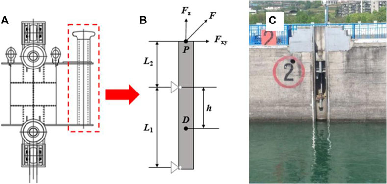
FIGURE 2. Floating mooring column of the lock: (A) structural diagram, (B) simplified calculation structure, (C) physical layout.
For any loading point D on the FMC of the lock, the corresponding total strain includes the axial tensile strain and the bending strain. Based on strain superposition, the strain at point D on the surface of the FMC of the lock can be stated by:
where ε1 represents the tensile strain, ε2 denotes the bending strain, A is the cross-sectional area of the FMC, E is the elastic modulus of the FMC, L1 is the length of the simply supported section of the FMC, L2 denotes the length of the outstretched arm of the FMC, h is the distance between the strain measurement position and the fulcrum point of the FMC, R represents the circle radius of the cross-section of the FMC, I is the moment of inertia of the annular section of the FMC, and d denotes the vertical distance between the strain measurement position and the neutral plane.
Within the range of the actual change of the mooring angles, the force analysis of the actual structure of the floating mooring column is carried out, and it is determined that the surface of the hollow cylinder near the vertical plane of the inner side of the lock wall line is always the tension zone, that is, the strain values are positive, and the bending strain generated by the lateral component force and the strain generated by the vertical component force can be avoided by choosing this area as the strain measurement location. Three strain measurement positions (i.e., B, C, and D) are selected on the surface of the axial cross-section of the dock FMC, and the factor h is set to 600 mm. Then, welded strain gauges are used to conduct measurements at the positions presented in Figure 3, which the standard range of welded strain gauges is ±3000με, the resistance deviation is less than or equal to ±0.1%, the sensitivity coefficient dispersion is less than or equal to ±2%, and the creep is less than or equal to 2 μm/m. The L1 section containing these measurement positions represents the non-mooring work area of the mooring column to prevent the strain gauge from being damaged by cables during operation. The angle between measurement positions B and C and the circle centre is denoted by μ, which is set to 10°. Furthermore, the angle between measurement positions C and D and the circle centre is represented by φ, which is set to 10°. The angle between the gate wall line and the line connecting measurement position B and the circle centre is represented by θ, which is set to 80°.
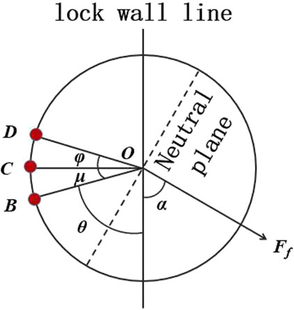
FIGURE 3. Strain monitoring positions and related angles of the dock FMC.
Based on the characteristics of the mooring load, the horizontal angle between the cable and the gate wall line is represented by α, and the vertical angle between the cable and the horizontal plane is represented by β. Then,
As presented in Figure 3, the strains of monitoring points B, C, and D are εB, εC, and εD, respectively. Using Eqs 1–3, the total strains at these points are evaluated as:
where
On the basis of Eqs 2–6, the following parameters can be readily evaluated: the horizontal angle between the mooring cable and the gate wall line (α), the vertical angle between the mooring cable and the horizontal plane (β), and the applied mooring load Ff at the specified height.
2.2 Physical model analysis
The rationality of the mooring load calculation method proposed in this paper is verified by a generalized physical model test of the load response. According to the true size and material of the upper structure of the FMC, a generalized physical model is established, and strain gauges are welded at the specified strain measurement positions. The mooring load of the FMC and the exerted loads with various mooring cable angles are simulated. The test process is depicted in detail in Figure 4.
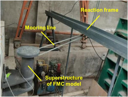
FIGURE 4. Physical model test site of the corresponding dock FMC.
Under a variety of loading conditions, the strain results are analysed by employing Eqs 4–6, and then the mooring load and mooring cable angle are calculated. The calculated data are compared with the standard values for the mooring load. The considered loads are presented in Table 1.

TABLE 1. Various loading scenarios of the physical model test.
Figure 5 illustrates that the errors of the calculation results are all less than 10% compared to the standard values of the physical model test. The results include the mooring load at the specified height of the dock FMC, the horizontal angle between the cable and the lock wall line, and the vertical angle between the cable and the horizontal plane. This comparison procedure therefore verifies the proposed calculation method of the mooring loads of the FMC.
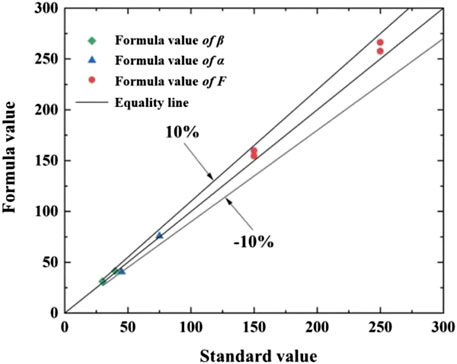
FIGURE 5. Calculation error analysis of the mooring load of the dock FMC.
2.3 Simulation model analysis
To further check the accuracy of the mooring load calculation model, a finite element numerical simulation is conducted. The main aim is to compare the calculation results of Eqs 4–6 with those of the numerical simulation. For this purpose, a three-dimensional (3D) numerical simulation model of the upper structure of the FMC is established by employing the ANSYS Workbench and the true size of each component of the FMC, as illustrated in Figure 6.
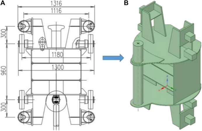
FIGURE 6. Dock FMC: (A) dimensions (mm), (B) 3D numerical simulation model.
Each component of the upper structure of the FMC comprises three materials: cast steel (ZG310-570) in the hollow cylinder column, stainless steel (1CR18Ni9Ti) in the three plates of the fixing hollow cylinder, and Q235 steel in the other components. The material properties are presented in Table 2.
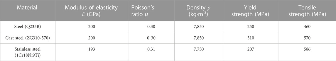
TABLE 2. Material properties of the upper structural components of the FMC.
In these numerical simulations, the permanent load acting on the upper structure of the dock FMC is considered as follows.
(1) The structure weight is specified as G = 8.1554 kN, with a vertically downward action direction.
(2) The water buoyancy force is set equal to the structure weight, with an action direction opposite to the weight.
The numerical simulation conditions of the dock FMC are given in Table 3.
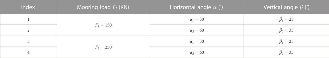
TABLE 3. The parameters used for numerical simulations in various cases.
The three-dimensional numerical simulation model of floating mooring column of lock was meshed by hexahedron meshing method provided by ANSYS Workbench, the single mesh size is a parallelepiped with sides of 10 mm, and the total number of meshed cells was 69,796. According to the previous research results of our team, the research works related to grid-independence tests were carried out, and compared the calculation results of the simplified calculation model of floating mooring column with the numerical model with the same mesh structure and mesh size in this paper. The relative error of the two results is only 3.6% (Liu M W et al., 2020), which is sufficient to show that the mesh structure and mesh size selected by the model in our study can provide sufficient calculation accuracy.
The stress distribution diagram of the upper structure of the FMC is evaluated on the basis of the numerical simulation, as shown in Figure 7.
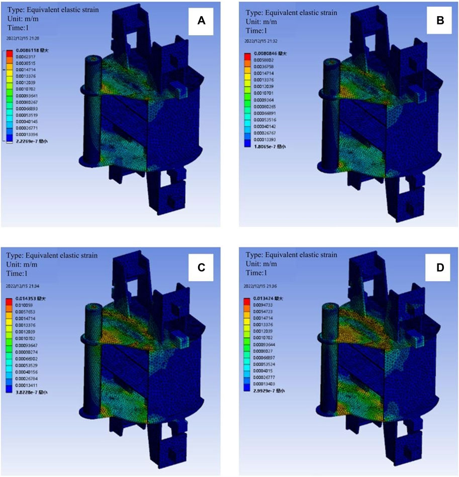
FIGURE 7. Stress distribution obtained from the numerical simulations under various operating conditions: (A) case 1, (B) case 2 (C) case 3, and (D) case 4.
Figure 7 indicates that the strain within the hollow cylinder of the FMC is greater than that of other positions. Particularly at the welding position of the three stainless steel plates near the hollow cylinder, the stress distribution is more noticeable. Such a distribution prevents the strain gauge from being damaged by the cable in actual operation.
The strain at each measurement position of the FMC is obtained by the numerical simulation, as presented in Figure 8A.
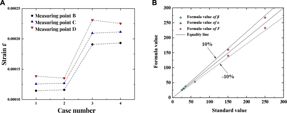
FIGURE 8. Test results based on the numerical simulation test: (A) strain calculation results, (B) simulation errors of the dock FMC model. (B) demonstrates the maximum relative discrepancies between the calculation results based on Eqs 4–6, with the numerical simulation results in the range of ±10%. Therefore, the proposed formulations are reasonably validated by the finite element numerical simulations.
To validate the accuracy of the simulation model under the action of load, strain simulations are carried out using Eqs 4–6 to evaluate the ship mooring load, the horizontal angle, and the vertical angle. The obtained results are then compared with the pre-set standard values of the numerical simulation test, as presented in Figure 8B.
3 Optimal regulation of the water delivery process of shiplock
3.1 Analysis of the judgement criteria
According to the proposed mooring load calculation method, the mooring force is calculated by measuring the tension and strain in the simulated mooring environment and combining with the actual ship operation conditions. It is found that the change of mooring force calculated by the simulated mooring environment under common mooring conditions is basically consistent with the experience of shiplock operation. The following is the simulation curve of mooring load (from the ship entering the lock to the opening of the opposite lock after water release) on different mooring positions (after spring line, head line, stem line) of a shiplock, as illustrated in Figure 9.
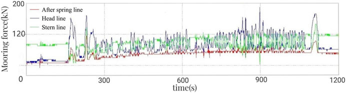
FIGURE 9. Plot of the mooring load simulation of the entire mooring process.
The performed analyses reveal that the initial peak of the mooring load is mainly produced during the berthing braking of the ship. The force peak can be improved through better system management. The irregular fluctuations with small amplitudes in the water delivery process are produced by the flow force and the operation barrier of the FMC. The magnitude of these fluctuations is commonly trivial in normal operating conditions. The final force peak occurs when the gate is opened after water delivery, causing the mooring column force to magnify and exceed the upper limit of the design. This issue guides us to the conclusion that the load setting must be properly optimized.
Based on the pertinent design specifications (JTJ 306-2001, 2001), the maximum load of the FMC largely relies on the longitudinal horizontal component of the mooring load, including the gradient force and the wave force acting on the ship. Essentially, the rate of the applied force exhibits no influence and is related to inertial superhigh linearity. The corresponding theoretical calculations are given as:
The parameters and coefficients given in Eqs 7–9 have previously been introduced and defined in Ref. (JTJ 306-2001, 2001).
The exerted loads on the FMC are complex in real operating conditions. In addition, the shiplock operation-monitoring program opens the gate before the massive inertia reaches its maximum value, as shown in Figure 10. This decision is made to lessen the damage caused by the massive inertia on the gate hoist and the motor. The error of the theoretical calculation under static loading is large. Hence, the theoretical calculation is not suitable for determining the operational state.
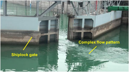
FIGURE 10. The gate is opened in advance to lessen the super high inertia.
Therefore, the horizontal and longitudinal forces of the FMC can be rationally chosen as an indicator of the safety state. The longitudinal horizontal component of the mooring load is denoted as PL, while the upper design limit of PL is assumed to be 15 t. The protection system is denoted as k. The upper design limit of the massive inertia (d) is assumed to be 0.25 m. The judgement condition of the safety state of the FMC at the end of the water delivery is given as:
3.2 Optimization method
An optimization criterion is commonly used to maintain Fy and d values below the safe mooring thresholds and to lessen the water delivery time as much as possible. Thus, a distinct progressive prototype debugging approach can be implemented as explained in the following.
During the water filling process of the large dock, including the moving water shut-off valve mode, the parameters to be optimized are: the residual water head (△H), the opening degree of the moving water shut-off valve (N), and the waiting time of the flush (△t). The following initial values are taken into account for the operating parameters: △H = 6.5 m and N = 0.70. The first debugging value of △H is set as △H1 = △H0 + 0.5. The first debugging value of N is also set equal to N1 = N0. In addition, the debugged values are set as follows: △H=(△H0, △H1, △H2, … , △Hm), △t = (△t0, △t1, △t2, … , △tm), and N = (N0, N1, N2, … , Na).
Additional factors are set up as follows. The valve opening from fully closed to fully opened is assumed to range from 0 to 1. The parameter values of x and y are assumed to be integers between 1 and 5, and the factor d0 is set equal to 0.25 m.
The debugging method was itemized per the following descriptions.
I. Open the water-filling valve to opening 1. In the case of △H = △Hm, start to close the water shut-off valve and stop closing the valve as soon as N = Na. Continue to fill the water until the water level of the gate chamber is flush with the upstream water level. Evaluate the massive inertia, namely, d, and the waiting flush time, i.e., △t.
II. Adjust the residual water head (△H) or the water shut-off valve opening (N) according to d and △t. Repeat step I to debug with adjusted △H and N to evaluate d and △t simultaneously.
III. When d = d0, the debugging of valve closing of the water filling valve is completed. When △t = 0 and N = N0, the debugging of the residual water head of the moving water shut-off valve is finished.
IV. In the optimized plan, we set the following conditions:
To keep the valve closed or open, with the value of N1 remaining unchanged. The debugging processes are repeated, and △t and d are simultaneously computed.
V. In the optimized plan, the following conditions are imposed:
To keep the residual water head △H2 of the moving water shut-off valve unchanged and repeat the debugging process.
VI. In the optimized plan, when △t = 0 and d = d0, debugging is completed. Subsequently, △H and N represent the final operating parameters.
3.3 Validation of the optimized results
A double-sided water-filling operation is chosen for validation testing. The moving water shut-off valve process is adopted. The test ship is the largest 6,000 t class standard single ship (with a large aspect ratio) on the Yangtze River. The initial parameters are set as △H = 6.5 m and N = 0.70. The numerical simulations are conducted according to the above debugging method to preliminarily monitor multiple groups of shut-off valve process parameters, as presented in Table 4.
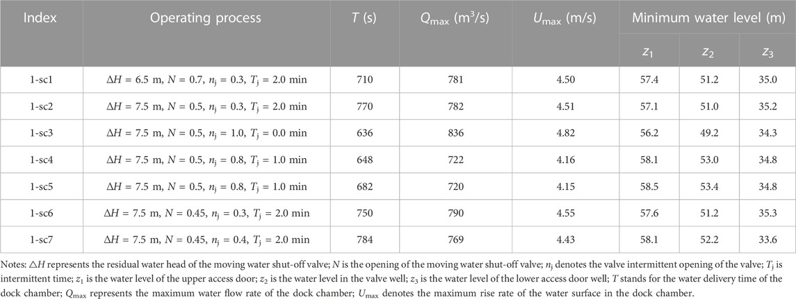
TABLE 4. Hydraulic characteristics of the debugged conditions.
The problem is appropriately calculated and analysed for multiple operating conditions. The operation process is selected as △H = 7.5 m and N = 0.45 based on a comprehensive consideration including the massive inertia and water delivery time. The massive inertia is measured to be d = 0.1 m ≤ 0.25 m.
The monitoring data of the mooring load (PL) are illustrated in Figure 11.
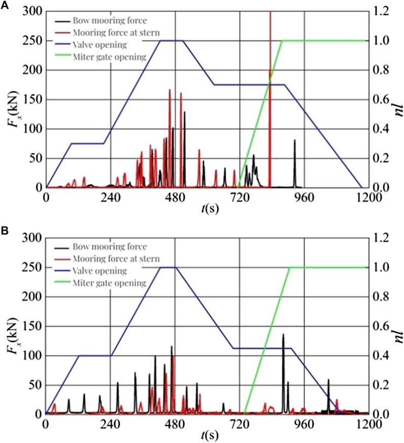
FIGURE 11. Mooring load as a function of time: (A) before optimization, (B) after optimization.
Figure 11 reveal that the dock with double-side water filling operates in a normal manner. For the single ship of 6,000 t class in the initial processes of water filling and levelling, the maximum mooring load PL is 300 kN (30.6 t) (see Figure 11A), noticeably exceeds the upper design limit of the load, which is 15 t for the FMC. After process optimization, the maximum mooring load decreases to 136.5 kN (13.9 t) (see Figure 11B), lower than the upper design limit with a noticeable reduction in the maximum mooring load; furthermore, the corresponding time of water delivery slightly increases. As a result, the process optimization method proposed in the current exploration is capable of effectively enhancing the safety of the ship mooring and suitably achieving a favourable balance with respect to effective water delivery.
4 Conclusion
A newly developed load inversion algorithm is established, which is suitable for the main structural and operational characteristics for the FMCs of sea shiplock. The selection of strain monitoring positions on the column is suitably optimized to eliminate the shortcomings of former methodologies. The detection accuracy of the FMC mooring loads is controlled by verification of physical model test and numerical simulation test with errors less than 10%, in addition, the smaller the β is, the smaller the error of the calculated value of the mooring force relative to the standard value is, and the opposite is true for α.With regard to the complex loads applied on the FMC, the proposed approach is capable of essentially meeting the requirements of ship dock operation and management and therefore offers promising prospects in applications.
Many factors can affect the mooring load of the FMC. Based on the load response model established above, the FMC mooring load is obtained by inversion calculation, and the monitored load results are used to adjust and optimize the water delivery process of the shiplock. The final period of water delivery is selected in the present investigation to assess the operating condition with the highest risk, evaluate its safety state and optimize the operation process. Although this high-risk period is representative, other operating conditions should be considered in upcoming explorations. The proposed method is fundamentally constructed based on the static load concept of the hydraulic model of the ship dock. This method aims to simplify constraints across various ranges of the operational protection process of the ship dock. The experimental validation indicates that the optimized operating conditions offer an improved balance between ship mooring safety, water delivery efficiency, and operating equipment safety. Research on monitoring method of FMC mooring load state in shiplock water delivery can be further improved through the research results of this paper, which the optimization process of shiplock water delivery is guided, the efficiency of shiplock water delivery is improved, and technical support for the release process of shiplock water and the safe operation of mooring equipment is provided.
Data availability statement
The original contributions presented in the study are included in the article/Supplementary material, further inquiries can be directed to the corresponding authors.
Author contributions
Conceptualization, methodology, writing-original draft preparation: JQ. Formal analysis, validation: LL. Supervision, resources: TJ. Writing-review and editing: ZX. Investigation: JY. Visualization: LW. All authors contributed to the article and approved the submitted version.
Funding
This research is supported by the fund of the Three Gorges—Gezhouba Lock monitoring and management facility construction project (Capital-construction 190909), and the commissioned service project of Three Gorges Navigation Authority (Operation-maintain 221219). It was also completed with the help of the lock hydraulics research team of the Yangtze River Scientific Research Institute.
Acknowledgments
The authors would like to express their gratitude to American journal experts—AJE (https://www.aje.cn/) for the expert linguistic services provided.
Conflict of interest
The authors declare that the research was conducted in the absence of any commercial or financial relationships that could be construed as a potential conflict of interest.
Publisher’s note
All claims expressed in this article are solely those of the authors and do not necessarily represent those of their affiliated organizations, or those of the publisher, the editors and the reviewers. Any product that may be evaluated in this article, or claim that may be made by its manufacturer, is not guaranteed or endorsed by the publisher.
References
Alegre, M. A. A., and Tremblay, R. (2022). Finite element analysis of flexural response of steel joist top chord extensions. J. Constr. Steel Res. 190, 107122. doi:10.1016/j.jcsr.2021.107122
Battiston, C. C., Bombardelli, F. A., Schettini, E. B. C., and Marques, M. G. (2020). Mean flow and turbulence statistics through a sluice gate in a navigation lock system: A numerical study. Eur. J. Mech. B 84, 155–163. doi:10.1016/j.euromechflu.2020.06.003
Chen, M., Ouyang, M., Guo, H., Zou, M., and Zhang, C. (2023). A coupled hydrodynamic-structural model for flexible interconnected multiple floating bodies. J. Mar. Sci. Eng. 11, 813. doi:10.3390/jmse11040813
Dev, A. K. (2018). Various aspects of bollard pull tests and analysis of test results. J. Sh. Prod. Des. 34, 249–268. doi:10.5957/JSPD.170001
Esferra, R., De Melo Bernardino, J. C., and Alfredini, P. (2018). Physical modeling applied in evaluation of the safety and efficiency of vessel mooring plans. Braz. J. Water Resour. 23, e33. doi:10.1590/2318-0331.231820170192
Gao, F., Hu, K., Shen, W. J., and Li, Y. (2021). Study on the safety guarantee of ship mooring from frequent cable accidents. IOP Conf. Ser. Earth Environ. Sci. 621, 012007. doi:10.1088/1755-1315/621/1/012007
Gholipour, G., Zhang, C., and Mousavi, A. A. (2020). Nonlinear numerical analysis and progressive damage assessment of a cable-stayed bridge pier subjected to ship collision. Mar. Struct. 69, 102662. doi:10.1016/j.marstruc.2019.102662
Gubesch, E., Abdussamie, N., Penesis, I., and Chin, C. (2022). Effects of mooring configurations on the hydrodynamic performance of a floating offshore oscillating water column wave energy converter. Renew. Sustain. Energy Rev. 166, 112643. doi:10.1016/j.rser.2022.112643
Huo, F., Xu, J., Yang, H. K., Yuan, Z. J., and Shen, Z. X. (2023). Study on characteristics of mooring system of a new floating offshore wind turbine in shallow water by experiment. Front. Energy Res. 10, 1007996. doi:10.3389/fenrg.2022.1007996
Jiang, C., el Moctar, O., and Zhang, G. (2023). Seakeeping criteria of a moored and articulated multibody floating platform in head seas. Front. Mar. Sci. 10, 1138235. doi:10.3389/fmars.2023.1138235
JTJ 306-2001 (2001). Design code for filling and emptying system of shiplocks. Beijing: People's Communications Press. (in Chinese).
Kašpar, T. (2022). Analytical determination of longitudinal forces on the vessels during filling of the navigation lock. IOP Conf. Ser. Mater. Sci. Eng. 1252, 012050. doi:10.1088/1757-899X/1252/1/012050
Kašpar, T., Fošumpaur, P., Králík, M., and Zukal, M. (2021). Parametric study of direct filling system of medium-head navigation locks. Pollack Period 16, 43–49. doi:10.1556/606.2020.00261
Lee, S. W., Lee, H. T., Kim, D. G., and Cho, I. S. (2019). Identification of impact factors in ship-to-ship mooring through sensitivity analysis. J. Navig. Port. Res. 43, 310–319. doi:10.5394/KINPR.2019.43.5.310
Li, R., Xiao, H., Xiao, X., Zhang, J., and Pan, L. (2022). Torsional deformation analysis of large miter gate under different operating conditions. Energies 15, 978. doi:10.3390/en15030978
Liu, B. J., Chen, X. Y., Zhang, Y. Q., Xie, J., and Chang, J. (2020). Influence of regular wave and ship characteristics on mooring force prediction by data-driven model. China Ocean. Eng. 34, 589–596. doi:10.1007/s13344-020-0053-1
Liu, M. W., Zeng, L. Q., and Qi, J. L. (2020). Numerical simulation of stress state of floating bollards of ship lock. Port. Waterw. Eng. 112-117. doi:10.16233/j.cnki.issn1002-4972.20201202.007
Nugroho, A., KhaeromanNubli, H., Prabowo, A. R., and Yudo, H. (2020). Finite element based analysis of steering construction system of ORCA class fisheries inspection ship. Procedia Struct. Integr. 27, 46–53. doi:10.1016/j.prostr.2020.07.007
Pawar, R., Bhar, A., and Dhavalikar, S. S. (2018). Numerical prediction of hydrodynamic forces on a moored ship due to a passing ship. Proc. Inst. Mech. Eng. M. J. Eng. Marit. Environ. 233, 575–585. doi:10.1177/1475090218770039
Rubinato, M., Luo, M., Zheng, X., Pu, J. H., and Shao, S. (2020). Advances in modelling and prediction on the impact of human activities and extreme events on environments. Water 12, 1768. doi:10.3390/w12061768
Sakakibara, S., Sunahara, S., Ito, K., and Kubo, M. (2018). Preliminary study on characteristics of motions of side-by-side moored vessels during waves in port. J. Jpn. Inst. Navig. 139, 33–47. doi:10.9749/jin.139.33
Shi, Y., Li, S., Chen, H., He, M., and Shao, S. (2018). Improved SPH simulation of spilled oil contained by flexible floating boom under wave–current coupling condition. J. Fluids Struct. 76, 272–300. doi:10.1016/j.jfluidstructs.2017.09.014
Van Den Van, P. P. D., and Van Loon, O. (2018). “The interaction of a lock's filling jet and the ship in the lock chamber, using scale model measurements,” in 7th international symposium on hydraulic structures (Utah: Utah State University).
Verelst, K., Vercruysse, J. B., and De Mulder, T. (2018). “Comparison of software for computation of longitudinal forces on a ship in a lock chamber during levelling with openings in the lock gate. Daniel Bung, Blake Tullis,” in 7th IAHR international symposium on hydraulic structures, Aachen, Germany, 15-18 May.
Wijsman, J. W. M. (2013). Panama canal extension: A review on salt intrusion into gatun lake. Wageningen UR: IMARES - Institute for Marine Resources & Ecosystem Studies, 7–15.
Wu, J. (2019). Safety assessment method for bollard structure based on standard mooring force inversion. Port. Waterw. Eng. 60-64. doi:10.16233/j.cnki.issn1002-4972.20191202.003
Yang, C., You, Z., Bai, X., Liu, Z., Geng, J., and Johanning, L. (2021). Experimental and numerical analysis on the mooring tensions of the coupled tunnel-barge system in waves. Ocean. Eng. 235, 109417. doi:10.1016/j.oceaneng.2021.109417
Yu, B., and He, M. W. (2018). Comparative study on Chinese and foreign calculation methods of mooring forces. Port. Eng. Technol. 55, 63–66. doi:10.16403/j.cnki.ggjs2018S116
Zhang, J., Ning, P. B., and Zhang, C. (2019). Research on calculation method of wave load and mooring force based on time domain potential flow theory. J. Def. Manag. 9, 1–8. doi:10.35248/2167-0374.19.9.180
Zhang, S., Villavicencio, R., Zhu, L., and Pedersen, P. T. (2019). Ship collision damage assessment and validation with experiments and numerical simulations. Mar. Struct. 63, 239–256. doi:10.1016/j.marstruc.2018.09.005
Zhu, L., Cai, W., Chen, M., Tian, Y., and Bi, L. (2020a). Experimental and numerical analyses of elastic-plastic responses of ship plates under ice floe impacts. Ocean. Eng. 218, 108174. doi:10.1016/j.oceaneng.2020.108174
Zhu, L., Liang, Q., Chen, M., and Zhang, S. (2020b). On the fluid-structure response of elastic-plastic ship sides subjected to impact loads. Mar. Struct. 70, 102698. doi:10.1016/j.marstruc.2019.102698
Keywords: sea lock, structural load monitoring, floating mooring column, water conveyance system operation, optimal regulation
Citation: Qi J, Li L, Jiang T, Xiang Z, Yang J and Wu L (2023) Structural load monitoring of floating mooring column and its application on optimal regulation for water conveyance system operation of sea shiplock. Front. Energy Res. 11:1218430. doi: 10.3389/fenrg.2023.1218430
Received: 07 May 2023; Accepted: 18 July 2023;
Published: 27 July 2023.
Edited by:
Jieming Ma, Xi’an Jiaotong-Liverpool University, ChinaReviewed by:
Mingsheng Chen, Wuhan University of Technology, ChinaXiaohui Zhu, Xi’an Jiaotong-Liverpool University, China
Copyright © 2023 Qi, Li, Jiang, Xiang, Yang and Wu. This is an open-access article distributed under the terms of the Creative Commons Attribution License (CC BY). The use, distribution or reproduction in other forums is permitted, provided the original author(s) and the copyright owner(s) are credited and that the original publication in this journal is cited, in accordance with accepted academic practice. No use, distribution or reproduction is permitted which does not comply with these terms.
*Correspondence: Zhouyu Xiang, eHp5QG1haWxzLmNxanR1LmVkdS5jbg==; Linjian Wu, d2xqYWJnZkAxMjYuY29t