- 1Design of Mechanical Elements and Systems R&D Center, Faculty of Product Design and Environment, Transilvania University of Brasov, Brasov, Romania
- 2Renewable Energy Systems and Recycling R&D Center, Faculty of Product Design and Environment, Transilvania University of Brasov, Brasov, Romania
The paper presents a comparative analysis on the steady-state behavior of two counter-rotating wind turbines with same components, where the generator can operate as a counter-rotating (with both a mobile rotor and stator—Case a) vs. conventional (with a fixed stator—Case b) electric machine. These wind energy conversion systems (WECSs) also have two coaxial counter-rotating wind rotors and a one-degree-of-freedom (1-DOF) planetary speed increaser with two inputs and one or two outputs for compatibility with the considered generator. The paper aims at highlighting the efficiency and energy performances of WECSs with a counter-rotating vs. conventional generator by investigating three functional scenarios (A, B, and C) of the two WECS cases (a and b) under the assumption of identical or different counter-rotating wind rotors. A generalized kinetostatic modeling algorithm is first proposed, starting from the general case of WECS with a counter-rotating generator, which allows the establishment of analytical relationships corresponding to speeds and torques at input and output shafts. Numerical simulations of the obtained closed-form model in each scenario highlighted the influence of the constructive parameters on WECS performances, as well as the energetic superiority of WECS, with a counter-rotating generator (Case a) vs. conventional generator (Case b): higher efficiency by 1.2% and more output power by 1% (Scenario A) to 5.5% (Scenario C).
1 Introduction
The European Union (EU) released a revised directive concerning sustainable energy in 2018 (European Union, 2018) which establishes a mandatory objective at the EU level stating that the share of energy from sustainable sources should be at a minimum of 32% until 2030, adding a clause which would allow an ascending revised growth of this percent until 2023 (Windeurope, 2017). Wind energy is the source with the highest percentage of energy production out of the total amount of sustainable energy in EU, and onshore and offshore wind energy is estimated to represent approximately 21% of electric energy production by 2030. When considering the built environment, a main challenge in designing and implementing wind energy conversion systems (WECS) is to get increased efficiency and energy production that can become main arguments toward choosing sustainable energy.
The growth of energetic performance of wind turbines and optimization of wind potential harnessing can be conducted through different technical solutions converging into one main direction—optimization of the conversion of wind energy into electric energy. This issue refers to the design of either the rotor, gearbox, or electric generator. Thus, the use of multi-rotor systems (Kale and Sapali, 2012) and counter-rotating (primary and secondary) rotors vs. single-rotor (conventional) WECS has proved to harvest more wind energy and, consequently, to increase the electricity production by approximately 40% (Li et al., 2013). Counter-rotating WECS contains two coaxial wind rotors rotating in opposite directions, which can be placed on the same side or on both sides of the nacelle. The primary rotor is the upwind rotor, and the secondary one—the downwind rotor. Vasel-Be-Hagh and Archer (2017) stated that using counter-rotating rotors is 22.6% more efficient in power production than using the single-rotor wind farms, while Circiumaru Oprina et al. (2022) established experimentally the efficiency of counter-rotating WECS on the diameters of the two rotors, with an increase in system efficiency of up to 49.14% being achieved for lower ratios between the diameters of front (upwind) and rear (downwind) rotors. Pacholczyk et al. (2017) demonstrated by simulation that a counter-rotating 5 MW wind turbine brings approximately 20% of additional power compared to the conventional type. Other results refer to the performance of counter-rotating WECS at different aerodynamic loads and blade pitch angles (Jung et al., 2005; No et al., 2009; Rosenberg et al., 2014; Blecharz and Pacholczyk, 2018; Wang et al., 2022), for different number of blades (Pamuji and Bramantya, 2019), various rotor axial distances (Irawan and Bramantya, 2016; Koehuan and SugiyonoKamal, 2017; Pacholczyk et al., 2019), or different rotor configurations (Radhakrishnan et al., 2022). Thus, Rosenberg et al. (2014) demonstrated that the power coefficient for counter-rotating rotors is influenced by the distance between the rotors and their diameters, increasing by 8%–9% when the distance equals the rotor radius and by 7% when the diameter of the upwind rotor is a quarter of the downwind rotor diameter. The pitch control strategy for a 1 MW dual-rotor wind turbine and the impact on its performance were established theoretically (No et al., 2009), both in steady-state and transient regimes, and the results concluded that the proposed model has to be refined by testing the turbine in-site. Li et al. (Zhiqiang et al., 2018) analyzed the improvement of the power coefficient of a micro-counter-rotating wind turbine based on the aerodynamics, the diameters, and configuration of the two rotors and proved that the position of the secondary rotor influences the system efficiency. Moreover, Jung et al. (2005) studied a 30 kW counter-rotating WECS and concluded that the best performance can be obtained when the distance between the rotors is half the auxiliary rotor diameter with the power coefficient reaching 0.5. In addition, it was proved experimentally that the power coefficient decreases with the increase in the pitch angle. A 3 kW coaxial, multi-rotor horizontal-axis wind turbine was built and tested by Mitchell’s project team, demonstrating that its power output is approximately three times higher at low and medium wind speeds than a single-rotor turbine of the same diameter (Queen, 2007). All research works concluded that the counter-rotating configuration of rotors is preferable for small power applications rather than the single-rotor WECS.
Regarding the electric generators for WECS, Booker et al. (2010) and Habash et al. (2011) proposed the use of counter-rotating electrical generators for wind turbine applications in urban areas, which have a mobile rotor (GR) and mobile stator (GS) rotating in opposite directions due to their increased energy performance compared to the conventional (with a fixed stator GS) generators. The counter-rotating generator was further investigated in terms of performance and rotor topology by Kutt et al. (2020), Egorov et al. (2021), and Mirnikjoo et al. (2021) and in terms of optimized system configuration with counter-rotating rotors (Mirnikjoo et al., 2020; Ullah et al., 2022a; Ullah et al., 2022b). Cho et al. (2017) analyzedthe performance and control of a WECS with counter-rotating rotors and counter-rotating generator and concluded that this configuration can lower the tip speed ratio at which the power curve attains its maximum almost by half in comparison to the single-rotor system. The designers and developers of counter-rotating generators recommend their use mainly in low-power counter-rotating WECS connected directly to the rotors.
In order to achieve the higher speed requirement of the electric generator, the wind turbines need to include a gearbox for increasing the lower speed of wind rotors. Various types of speed increasers are presented and discussed in the literature: fixed-axis type (Jaliu et al., 2008a; Bevington et al., 2008; Marjanovic et al., 2012), planetary transmissions (Shin, 1999; Jaliu et al., 2008b; Jelaska et al., 2015; Saulescu et al., 2016a; Neagoe et al., 2017; Pastor et al., 2021), and variable speed transmissions (Erturk et al., 2018; Bharani and Sivaprakasam, 2020). Due to their advantages, i.e., high kinematic ratio, reduced radial size, and better efficiency, the researchers consider that the planetary speed increasers are suitable for both single-rotor systems, mainly for the high-power WECS, and for the multi-rotor WECS. For instance, Dong et al. (2017) and Vázquez-Hernández et al. (2017) investigated the parameters that affect the design and the conversion efficiency of WECS and concluded that the use of a planetary transmission is the best option for wind turbines.
In addition, in the counter-rotating WECS configurations, the planetary transmissions can operate either as one-degree-of-freedom (1-DOF) or two-DOF speed increasers, improving in both cases the wind turbine performance. The two operation cases were included by Qiu et al. (2017) in a synthesis of planetary transmissions used in WECS as possible gearboxes, while Saulescu et al. (2018) proposed an algorithm for the conceptual design of the planetary 1-DOF and 2-DOF speed increasers for different functioning situations. Various innovative solutions of planetary speed increasers were proposed (Saulescu et al., 2016b; Saulescu et al., 2018; Neagoe et al., 2019) for counter-rotating WECS. The performance in the steady-state regime of the different WECS configurations was investigated comparatively (Saulescu et al., 2016b; Neagoe et al., 2019; Saulescu et al., 2021; Neagoe and Saulescu, 2022), and a generalized approach for the efficiency analysis of 1-DOF speed increasers for counter-rotating WECS was proposed (Neagoe et al., 2020).
Recent research proved that the use of the counter-rotating generators can lead to a higher conversion efficiency of WECS than the conventional system (Saulescu et al., 2016a; Saulescu et al., 2016b; Neagoe et al., 2017; Neagoe et al., 2019; Neagoe et al., 2020; Saulescu et al., 2021; Neagoe and Saulescu, 2022). However, only a few studies analyzed WECS configuration with both counter-rotating rotors and counter-rotating generator and proposed suitable mechanical transmissions (Neagoe et al., 2019; Neagoe et al., 2020; Neagoe and Saulescu, 2022). To the best of our knowledge, a major research gap identified in the literature review was the need for comparative analysis of these types of WECS in different structural–functional scenarios that allow their constructive optimization and highlight their benefits in comparison with WECS with a conventional generator.
The paper proposes two WECS configurations that combine the concepts of counter-rotating wind rotors and counter-rotating or conventional electric generator and integrate a novel 1-DOF planetary speed increaser with two inputs and two outputs. The proposed transmission can accommodate both the conventional generator and the counter-rotating generator. The paper proposes a generalized modeling approach of these two types of counter-rotating systems with a counter-rotating generator (Case a) vs. conventional generator (Case b) and compares their energy performance simulation results in the steady state by considering three scenarios. The same primary rotor and same electric generator are used for both cases in all scenarios, while the secondary rotor is designed as follows:
- Different in the two applications, being established from the condition of achieving the same ratio of input torques kt (Scenario A).
- Identical to the primary rotor R1 but operating at a torque and angular speed (in absolute value) different from R1 (Scenario B).
- Identical to the primary rotor R1 and operating at a torque and angular speed (in absolute value) identical to R1 (Scenario C).
The remainder of the paper is organized as follows: two WECS configurations (Case a and Case b), consisting of two counter-rotating rotors—a 1-DOF speed increaser and a counter-rotating or conventional electric generator, are proposed in Section 2. Section 3 presents a generalized analytical kinematic modeling, and the torque and efficiency modeling algorithm is proposed in Section 4, based on the input torque ratio kt. Section 5 deals with the expression of the kt ratio and the mechanical characteristics of the rotors and generator, while Section 6 provides the expressions of the operating point for the proposed WECS configurations. Section 7 presents the numerical simulations and discussions for the three scenarios, and Section 8 is devoted to final conclusions.
2 Problem formulation
The two WECSs with counter-rotating rotors (R1—primary rotor and R2—secondary rotor) considered in this comparative study are schematically illustrated in Figure 1. The analysis is based on the following correlation: the second variant (Figure 1B) can be obtained from the counter-rotating system with two outputs (materialized by the rotor GR and the stator GS of a counter-rotating generator Gc, Figure 1A) by breaking the connection between the speed increaser SI and the stator GS and by fixing the stator (Figure 1B). Therefore, the mathematical models derived in the general case of systems with a counter-rotating generator (Case a) allow proving the results obtained for systems with a conventional generator G (Case b) by customizing the GS stator state.

FIGURE 1. Conceptual diagrams of the WECS considered in the comparative analysis: systems with a counter-rotating generator (A) and conventional generator (B).
The following assumptions are used in the comparative analysis of the two WECSs:
• Both WECSs use the same mechanical transmission SI, for which the following parameters are known: internal kinematic ratio and internal efficiency.
• The same mechanical characteristics are considered for the homologous wind rotors on the one hand and for the electric generators (both conventional and counter-rotating) on the other hand.
• The ratio of the torques of the two wind rotors
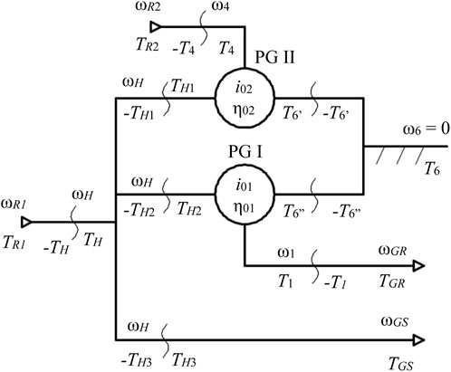
The planetary speed increaser (Figure 2) is a complex transmission consisting of two parallel-connected 1-DOF planetary gear sets, 1-2-3-5-6-H (PG I = 01) and 4-3-5-6-H (PG II = 02), which have three sun gears (1, 4, and 6) and a common planet carrier H (Figure 3). The internal kinematic ratios of the two planetary gear sets are denoted by
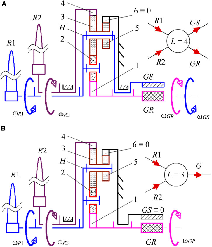
FIGURE 2. Structural schemes and block diagrams of the 1-DOF systems with a counter-rotating generator (A) and conventional generator (B).
According to Figure 2A; Figure 3, the WECS with two counter-rotating wind rotors (R1 and R2), a speed increaser (1-2-3-4-5-6-H), and a counter-rotating electric generator Gc uses a planetary transmission with two inputs (H ≡ R1—primary input; 4 ≡ R2—secondary input) and two outputs (1 ≡ GR—primary output; H ≡ GS—secondary output). Thus, the 1-DOF planetary speed increaser transmits the mechanical power from the counter-rotating wind rotors to the electric generator whose rotor and stator rotate in opposite directions. This 1-DOF planetary mechanism has the property of a) summing the input torques from the wind rotors (torque-adding) and b) transmission in a determined way of an independent external motion to the other three exterior links. Overall, the planetary transmission (Figure 2A) has four inputs and outputs (L = 4): conventionally, the primary input is connected to the wind rotor R1, and the secondary input is connected to the wind rotor R2; the two outputs are connected to the rotor GR and to the stator GS. According to Figure 2A, the secondary input R2 is connected directly to the stator GS. Because the transmission from Figure 2B can be obtained by breaking the connection between the secondary output H and the generator stator and by fastening the stator GS to the base, its kinematic and static model can be derived as a particular case of the mathematical model of the speed increaser from Figure 2A.
The kinematic and static (torque) correlations, which are systematized in relationships (1)–(3), (4), and (5), refer to the systems shown in Figure 2 and allow highlighting their performance by considering the mechanical characteristics of the wind rotors and the generator or the behavior of one wind rotor in relation to the other. The efficiency of the transmission can be determined either based on the torques of the two wind rotors or by using the torque of the primary rotor (TR1) and the input torque ratio kt.
3 Kinematic modeling
The specific kinematic correlations of the speed increaser and its connections to the external links can be written according to Figure 3 starting from the general relationships of a planetary gear set (Neagoe et al., 2020).
Considering the motion of the rotor R1 as an independent parameter, Eq. 1 highlights the kinematic correlations specific to the isolated subsystems:
• Input shafts:
• Planetary gear sets:
• Transmission connections with the generator stator and rotor:
• The transmission functions of the system:
Based on the aforementioned equations, the kinematic transmission functions can be obtained as follows:
• 1-DOF speed increaser with two counter-rotating inputs and two counter-rotating outputs, as shown in Figure 2A:
• 1-DOF speed increaser with two counter-rotating inputs and one output, as shown in Figure 2B (
4 Torques and efficiency modeling
Analogous to the kinematic modeling, the static modeling is performed using the block diagram shown in Figure 3, which allows identifying the static correlations specific to the two planetary gear sets, the equilibrium equations of the links between them and also of the external connections, and the static transmission function. These relationships together with the mechanical characteristics of the wind rotors and the counter-rotating/conventional electric generator can be used for identifying the following: the operating point of the machine of wind rotors—speed increaser—electric generator type; the mechanical power obtained at the input of the electric generator; the power flow through the speed increaser and its efficiency; and the influence of the ratio
For the 1-DOF speed increaser with two counter-rotating inputs and two counter-rotating outputs, as shown in Figure 2A, the equality
• Input shafts:
• Internal shafts:
• Planetary gear sets (PG I and PG II):
• Transmission connections with the generator stator and rotor:
• Transmission functions of the system:
• The mechanical characteristics of the wind rotors and the electric generator:
• For the 1-DOF speed increaser with two counter-rotating inputs and one output, as shown in Figure 2B, Eq. 4 is particularized for the fixed stator and
In order to avoid possible confusions, the static parameters belonging to the system with a conventional generator, that have different values than those of the first case, are marked with an asterisk.
5 Determination of the kt ratio
In the general case, the static ratio
• Case a, see Figure 2A and Eq. 4:
By replacing the mechanical characteristics presented in Eq. 4 into Eq. 6 and by considering the kinematic correlations from Eqs 1, 2, the following equation system is obtained:
The
By denoting
it is obtained
Case b, see Figure 2B and Eq. 5:
Similar to the previous case, by combining Eqs 1, 3, 5 with system (11), it is obtained
The ratio
where A, B, C, D, and E are defined by Eq. 9.
Taking into account Eqs 2–5, the expressions of the constants
An equation of
As the angular speed
6 Determination of the operating point
The analytical relationships of the kinematic and static parameters are systematized comparatively in Table 1 for both analyzed WECSs.
The parameters of the operating point (F) reduced on the shaft connected to the generator rotor can be also obtained for the two cases:
• Case a, Figure 2A (see Eqs 2, 4):
• Case b, Figure 2B (see Eqs 3, 5):
7 Numerical results and discussion
For the purpose of comparative analysis, numerical simulations are further performed by considering that each of the two WECSs is characterized by the internal kinematic ratios
- The primary rotors R1 have the same mechanical characteristic (i.e., same values of
- The electric generators have the same mechanical characteristic in both cases (i.e., same values of
The behavior of the two WECSs is analyzed in three different scenarios, in which the secondary wind rotor and the speed increaser are modified according to the following assumptions:
Scenario (A): the static ratio in both cases is
Scenario (B): the rotors R2 of the two WECSs are identical with the rotors R1, but different values of kt are registered for the two cases.
Scenario (C): the rotors R2 are identical with the rotors R1 in both cases, and the same value of kt (kt = 1) is obtained for the two WECSs by changing
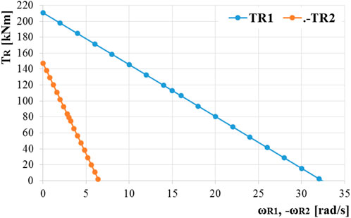
The values of the coefficients aR1,2 and bR1,2 from the mechanical characteristics of the wind rotors R1 and R2, which are dependent on the blade aerodynamic behavior, were obtained by applying the algorithm presented in Neagoe and Saulescu (2022). The behavior of the two types of WECSs is further presented comparatively based on the values of the kinematic and static parameters in the operating point, also following the influence of the mechanical characteristics on the system behavior and energy performance.
7.1 Comparative analysis in Scenario A
The coefficients of the mechanical characteristics describing the behavior of the rotors R2 are determined based on the previous data, by means of Eq. 17 and imposing
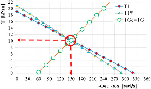
FIGURE 5. Operating points in Scenario A reduced on the shaft of the counter-rotating generator
Figure 6 details Figure 5 and presents comparatively the two operating points reduced on the transmission output shaft and the afferent mechanical powers. It shows that the output power in Case a is higher by ∼1% than that in Case b, due to the generator benefits of a higher torque and a higher angular speed, implicitly.
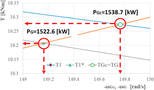
FIGURE 6. Operating points in Scenario A reduced on the generator shafts with the specification of the afferent mechanical power.
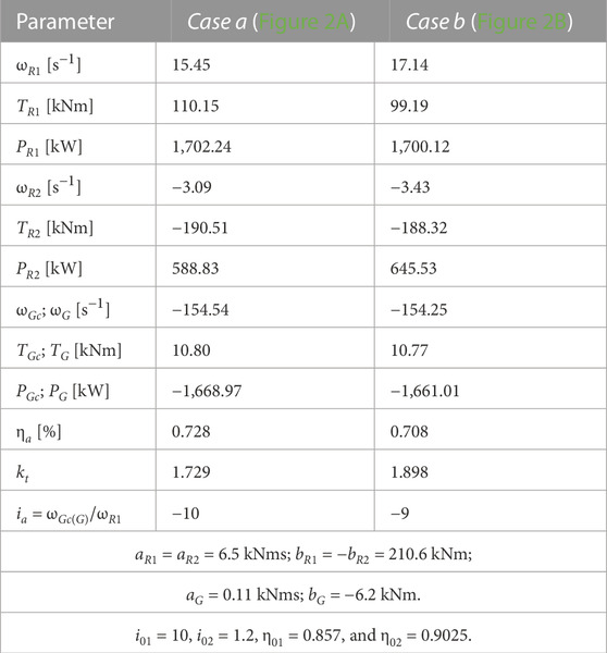
From the results systematized in Table 2, it appears that the efficiency of the system with a counter-rotating generator is higher than that of the system with a conventional generator; this aspect is due to the branched transmission of the mechanical power at the output of the speed increaser, in which case the power transmitted to the stator of the electric generator is without friction losses (Figure 3). In the case of the system with a conventional generator, the entire mechanical power is transmitted through the speed increaser only to the rotor of the electric generator, and implicitly, the frictional losses are higher. Therefore, considering a theoretical case of 1 kW cumulative input power generated by the two wind rotors, the 1-DOF transmission with two inputs and two outputs delivers to the generator a power of 795 W, while the system with two inputs and one output delivers a power of 783 W for the same static ratio
Due to the higher efficiency in Case a compared to Case b, an output power PGc > PG is obtained despite the lower powers of the rotors R1 and R2, where both rotors operate at lower speeds and higher torques. This phenomenon can be an advantage, especially at lower wind speeds.
7.2 Comparative analysis in Scenario B
The values obtained in this scenario are given in Table 3, by considering identical wind rotors in both cases. Similar to Scenario A, the counter-rotating generator system (Case a) achieves a slightly higher power output (by ∼0.5%) than Case b, as the mechanical power is flowing at a higher efficiency (0.728 vs. 0.708) due to the branched transmission of the output power. Implicitly, the counter-rotating generator operates at higher torque and rotational speed than the conventional generator.
In Case a, the rotor R2 extracts a lower power from wind and the rotor R1 extracts a higher power than Case b. The ratio
7.3 Comparative analysis in Scenario C
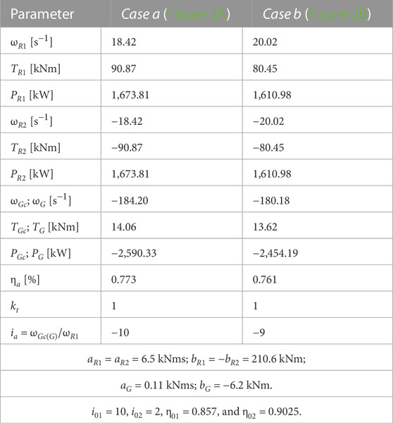
In order to meet the premise of
Table 4 shows the values of the operating points in Case a and Case b for Scenario C. By imposing the two rotors which rotate in opposite directions with the same speed, an increase in the power supply brought by the rotor R2 and a better efficiency are obtained compared with Scenario B. The kinematic and static relative behavior of the two cases is similar to the previous scenarios, with the efficiency of the speed increaser with two outputs bringing an improvement of ∼1.5%. In this scenario, both rotors R1 and R2 registered in Case a have higher power and torque, accompanied by smaller rotational speed, than those in Case b.
7.4 Power flow
Analytically, the static transmission functions can be determined either by solving the system of equations formed by the static relationships from Eq. 4 or using the “effects overlapping” method; according to this method, initially abstracting from the wind rotors and the electric generator, the static analysis of the considered 1-DOF mechanism with L = 4 can be reduced (due to its linear-type functions) to the analysis of L = 3 simpler 1-DOF mechanisms (L = 2); they are obtained from the initially considered mechanism (Figures 2A, 3), leaving non-null in turn for each of the three independent torques:
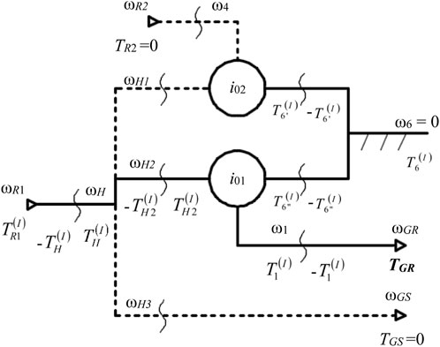
FIGURE 7. Block diagram of the planetary speed increaser from Figure 3 in the functional case of
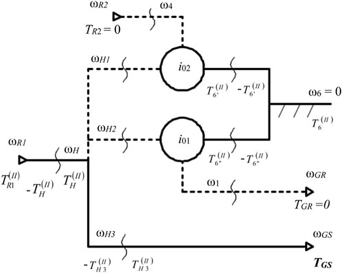
FIGURE 8. Block diagram of the planetary speed increaser from Figure 3 in the functional case of
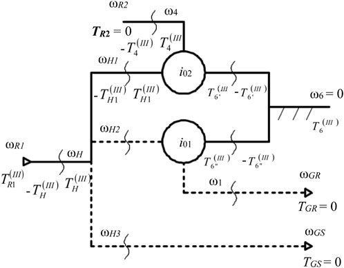
FIGURE 9. Block diagram of the planetary speed increaser from Figure 3, for which the independent torque
By “overlapping the static effects” of the mechanisms from Figures 7–9, the expressions of the static transmission functions of the initial mechanism (Figure 3) and the torque of the electric generator are obtained. Similarly, the other torques are determined (see Table 5) while being required in the organologic calculations.
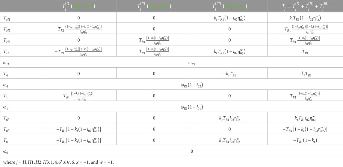
TABLE 5. Expressions of the torques and speeds for the speed increaser with two inputs and two outputs (Case a, Figure 3).
As explained in the problem formulation, the 1-DOF speed increaser with two inputs and one output (Figure 2B) was obtained from the speed increaser with two inputs and two outputs (Figure 3) by breaking the stator connection and by fixing it (i.e., ωGS = 0). This speed increaser with one output is a particular case of the one from Figure 3. Its internal torques and speeds are presented in Table 6 by processing the relationships (3) and (5).
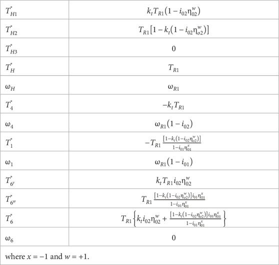
TABLE 6. Expressions of the torques and speeds for the speed increaser with two inputs and one output (Case b).
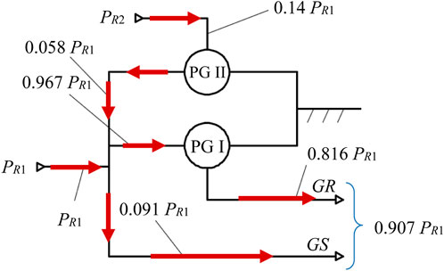
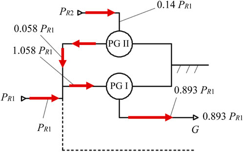
A modeling of the power flow from inputs to outputs in both cases is further developed by considering the input power of the primary rotor (
In both cases, the rotor R2 generates lower mechanical power than the primary rotor (0.14 PR1), which is then directed through the planetary gear set PG II and subsequently connected with power PR1. This cumulative power flows on two branches in Case a toward the generator rotor and stator (Figure 10) and is completely directed to the generator rotor in Case b, crossing the PG I. Due to the direct transmission of a significant power share to the GS (0.091 PR1, Figure 10), the output power in Case a is higher than in Case b (0.907 PR1 vs. 0.893 PR1).
8 Conclusion
The generalized algorithm presented in the paper refers to a 1-DOF planetary transmission with two inputs and two outputs (L = 4), used as a torque-adding speed increaser in WECS with two counter-rotating rotors and generator with a mobile stator.
The conclusions drawn from the comparative analysis of the obtained results under the considered premises show the following:
• A WECS with a 1-DOF speed increaser with two counter-rotating outputs achieves a higher efficiency than the WECS with a single output; considering the initial characteristics and a cumulative power of 1 kW at the input, the speed increaser with two counter-rotating outputs brings power gain of 1.2% compared to the case with one output.
• The mechanical characteristics can significantly influence the functionality of a system; for example, the WECS with the set of coefficients defined in Table 2 (Scenario A) achieves a higher efficiency than the homologous WECS with the set of coefficients from Table 3 (Scenario B): by 6.7% more in Case a and by 7.7% more in Case b.
• The correlation between the speeds of the wind rotors influences decisively their behavior, including static ratio
The considered planetary transmission reverses the direction of rotation with respect to the wind rotor R1, sums up the input torques, and increases the input speed
The efficiency of the 1-DOF transmission with two counter-rotating inputs and two counter-rotating outputs does not depend on the internal kinematic ratio i01 (Table 1) and thus on the amplification ratio.
Depending on the power required by the generator and the torque ratio, the proposed algorithm allows determining the mechanical power parameters on each branch, corresponding to the transmission outputs (rotor and stator of the electric generator).
The results of this work are limited to the steady-state behavior of WECS, where constant wind speed is considered and the inertial effects are null, implicitly. The authors intend in the future to address the problem of dynamic modeling and simulation of these WECS types by considering their body moments of inertia and their impact under transitory conditions at variable wind speeds and starting or stopping regimes. It is also intended to experimentally validate the numerical results by developing a specific stand for WECS small-scale prototypes.
Data availability statement
The original contributions presented in the study are included in the article/Supplementary Material; further inquiries can be directed to the corresponding authors.
Author contributions
Conceptualization, RS, CJ, MN, DC, and NC; methodology, RS, CJ, MN, DC, and NC; software, RS, DC, and NC; validation, RS, CJ, MN, DC, and NC; investigation, RS, CJ, MN, DC, and NC; interpretation, RS, CJ, MN, DC, and NC; writing—original draft preparation, RS, CJ, MN, DC, and NC; writing—review and editing, CJ and MN; supervision, MN and CJ. All authors contributed to the article and approved the submitted version.
Conflict of interest
The authors declare that the research was conducted in the absence of any commercial or financial relationships that could be construed as a potential conflict of interest.
Publisher’s note
All claims expressed in this article are solely those of the authors and do not necessarily represent those of their affiliated organizations, or those of the publisher, the editors, and the reviewers. Any product that may be evaluated in this article, or claim that may be made by its manufacturer, is not guaranteed or endorsed by the publisher.
References
Bevington, C. M., Bywaters, G. L., Coleman, C. C., Costin, D. P., Danforth, W. L., Lynch, J. A., et al. (2008). Wind turbine having a direct-drive drivetrain. U.S. Patent 7,431,567 B1.
Bharani, R., and Sivaprakasam, A. (2020). A review analysis on performance and classification of wind turbine gearbox technologies. IETE J. Res. 68, 3341–3355. doi:10.1080/03772063.2020.1756936
Blecharz, K., and Pacholczyk, M. (2018). Rotor blade performance analysis for small counter rotating wind turbine. Zesz. Nauk. Wydz. Elektrotechniki i Autom. Politech. Gdańskiej 61. doi:10.32016/1.61.13
Booker, J. D., Mellor, P. H., Wrobel, R., and Drury, D. (2010). A compact, high efficiency contra-rotating generator suitable for wind turbines in the urban environment. Renew. Energy 35, 2027–2033. doi:10.1016/j.renene.2010.02.003
Cho, W., Lee, K., Choy, I., and Back, J. (2017). Development and experimental verification of counter-rotating dual rotor/dual generator wind turbine: Generating, yawing and furling. Renew. Energy 114, 644–654. doi:10.1016/j.renene.2017.06.083
Circiumaru Oprina, G., Chihaia, R., Tanase, N., El-Leathey, A., and Voina, A. (2022). Increasing energy efficiency of counter-rotating wind turbines by experimental modelling. IOP Conf. Ser. Mater. Sci. Eng. 1235, 012064. doi:10.1088/1757-899X/1235/1/012064
Dong, H., Zhang, C., Wang, D., Xu, S., and Qiu, J. (2017). Dynamic characteristics of gear box with PGT for wind turbine. Procedia Comput. Sci. 109, 801–808. doi:10.1016/j.procs.2017.05.331
Egorov, A., Kaizer, Y., Lysyannikov, A., Kuznetsov, A., Shram, V., Pavlov, A., et al. (2021). Counter-rotating electric generator for wind power plants with liquid metal energy transfer. J. Phys. Conf. Ser. 2094, 052018. doi:10.1088/1742-6596/2094/5/052018
Erturk, E., Sivrioglu, S., and Bolat, F. C. (2018). Analysis model of a small scale counter-rotating dual rotor wind turbine with double rotational generator armature. Int. J. Renew. Energy Res. 8, 1849–1858. doi:10.20508/ijrer.v8i4.8235.g7549
European Union, (2018). Directive (EU) 2018/2001 of the European Parliament and of the Council of 11 December 2018 on the promotion of the use of energy from renewable sources. https://eur-lex.europa.eu/legal-content/EN/TXT/?uri=uriserv:OJ.L_.2018.328.01.0082.01.ENG&toc=OJ:L:2018:328:TOC.
Habash, R. W. Y., Groza, V., Yang, Y., Blouin, Ch., and Guillemette, P. (2011). Performance of a contrarotating small wind energy converter. Int. Sch. Res. Netw. ISRN Mech. Eng. 2011, 1–10. doi:10.5402/2011/828739
Irawan, Y., and Bramantya, A. “Numerical simulation of the effect of axial distance between two rotors in counter-rotating wind turbines,” in Proceedings of the 2016 2nd International Conference on Science and Technology-Computer (ICST), Yogyakarta, Indonesia, October 2016, 1–5. doi:10.1109/ICSTC.2016.7877338
Jaliu, C., Diaconescu, D. V., Neagoe, M., and Saulescu, R. “Dynamic features of speed increasers from mechatronic wind and hydrosystems. Part II. Dynamic aspects,” in Proceedings of the Second European Conference on Mechanism Science EUCOMES 08, Casino, Italy, September 2008.
Jaliu, C., Diaconescu, D. V., Neagoe, M., and Saulescu, R. “Dynamic features of speed increasers from mechatronic wind and hydrosystems. Part I. Structure Kinematics,” in Proceedings of the Second European Conference on Mechanism Science EUCOMES 08, Casino, Italy, September 2008.
Jelaska, D., Podrug, S., and Perkušic, M. (2015). A novel hybrid transmission for variable speed wind turbines. Renew. Energy 83, 78–84. doi:10.1016/j.renene.2015.04.021
Jung, S. N., No, T.-S., and Ryu, K.-W. (2005). Aerodynamic performance prediction of a 30kW counter-rotating wind turbine system. Renew. Energy 30 (5), 631–644. doi:10.1016/j.renene.2004.07.005
Kale, Sandip A., and Sapali, S. N. (2012). Comprehensive evaluation of innovative multi rotor wind turbine designs. Int. J. Mech. Eng. Technol. (IJMET) 3 (2), 730–739.
Koehuan, V., and SugiyonoKamal, S. (2017). Investigation of counter-rotating wind turbine performance using computational fluid dynamics simulation. IOP Conf. Ser. Mater. Sci. Eng. 267, 012034. doi:10.1088/1757-899X/267/1/012034
Kutt, F., Blecharz, K., and Karkosinski, D. (2020). Axial-Flux permanent-magnet dual-rotor generator for a counter-rotating wind turbine. Energies 13, 2833. doi:10.3390/en13112833
Li, Z., Wang, Y., and Xiao, H. “Experimental study on structures of counter-rotating wind turbines,” in Proceedings of the ICMREE 2013 - Proceedings: 2013 International Conference on Materials for Renewable Energy and Environment, Chengdu, China, August 2013. doi:10.1109/ICMREE.2013.6893685
Marjanovic, N., Isailovic, B., Marjanovic, V., Milojevic, Z., Blagojevic, M., and Bojic, M. (2012). A practical approach to the optimization ofgear trains with spur gears. Mech. Mach. Theory 53, 1–16. doi:10.1016/j.mechmachtheory.2012.02.004
Mirnikjoo, S., Abbaszadeh, K., and Abdollahi, E. (2020). Multi-objective design optimization of a double-sided flux switching permanent magnet generator for counter-rotating wind turbine applications. IEEE Trans. Industrial Electron. 68, 6640–6649. doi:10.1109/TIE.2020.3005106
Mirnikjoo, S., Asadi, F., Abbasazdeh, K., and Abdollahi, E. (2021). Effect of rotor topology on the performance of counter-rotating double-sided flux switching permanent magnet generator. IEEE Trans. Energy Convers. 37, 65–74. doi:10.1109/TEC.2021.3103555
Neagoe, M., and Saulescu, R. (2022). Comparative energy performance analysis of four wind turbines with counter-rotating rotors in steady-state regime. Energy Rep. 8, 1154–1169. doi:10.1016/j.egyr.2022.07.092
Neagoe, M., Saulescu, R., Jaliu, C., and Cretescu, N. (2017). “Novel Speed increaser used in counter-rotating wind turbines,” in New advances in mechanisms, mechanical transmissions and robotics, mechanisms and machine science (Berlin, Germany: Springer), 143–151.
Neagoe, M., Saulescu, R., and Jaliu, C. (2019). Design and simulation of a 1 DOF planetary speed increaser for counter-rotating wind turbines with counter-rotating electric generators. Energies 12, 1754. doi:10.3390/en12091754
Neagoe, M., Saulescu, R., Jaliu, C., and Simionescu, P. A. (2020). A generalized approach to the steady-state efficiency analysis of torque-adding transmissions used in renewable energy systems. Energies 13, 4568. doi:10.3390/en13174568
No, T. S., Kim, J.-E., Moon, J. H., and Kim, S. J. (2009). Modeling, control, and simulation of dual rotor wind turbine generator system. Renew. Energy 34 (10), 2124–2132. doi:10.1016/j.renene.2009.01.019
Pacholczyk, M., Blecharz, K., and Karkosinski, D. (2017). Modelling of the counter rotating wind turbine. Proc. XXVII Seminar Organ. by Pol. Soc. Theor. Appl. Electr. Eng. PTETiS, Gdańsk Sect. 57, 81–84.
Pacholczyk, M., Blecharz, K., and Karkosinski, D. (2019). Numerical investigation on the performance of a small counter-rotating wind turbine. Energy Mater. Sci. Eng. Energy Syst. 116, 00055. doi:10.1051/e3sconf/201911600055
Pamuji, D., and Bramantya, A. (2019). Numerical study on the performance of 2-bladed and 3-bladed counter rotating wind turbines. J. Jpn. Soc. Appl. Electromagn. Mech. 27, 169–174. doi:10.14243/jsaem.27.169
Pastor, D. G. S. B., Nalianda, D., Sethi, V., Midgley, R., Rolt, A., and Novelo, D. A. B. (2021). Preliminary design framework for the power gearbox in a contra-rotating open rotor. J. Eng. Gas. Turbines Power 143, 041022. doi:10.1115/1.4049411
Qiu, J., Liu, B., Dong, H., and Wang, D. (2017). Type synthesis of gearbox in wind turbine. Procedia Comput. Sci. 109, 809–816. doi:10.1016/j.procs.2017.05.333
Queen, R. (2007). Build and test a 3 kilowatt prototype of a coaxial multi-rotor wind turbine. San Diego, CA, USA: California Energy Commission.
Radhakrishnan, J., Zuber, M., Sridhar, S., Ng, E., and Shenoy, S. “Comparative analysis of counter rotating and conventional vertical axis wind turbine,” in Proceedings of the 2022 4th International Conference on Energy, Power and Environment (ICEPE), Shillong, India, April 2022, 1–6. doi:10.1109/ICEPE55035.2022.9798188
Rosenberg, A., Selvaraj, S., and Sharma, A. (2014). A novel dual-rotor turbine for increased wind energy capture. J. Phys. Conf. Ser. 524 (1), 012078. doi:10.1088/1742-6596/524/1/012078
Saulescu, R., Neagoe, M., and Jaliu, C. (2018). Conceptual synthesis of speed increasers for wind turbine conversion systems. Energies 11, 2257. doi:10.3390/en11092257
Saulescu, R., Neagoe, M., Jaliu, C., and Munteanu, O. (2021). A comparative performance analysis of counter-rotating dual-rotor wind turbines with speed-adding increasers. Energies 14, 2594. doi:10.3390/en14092594
Saulescu, R., Neagoe, M., Jaliu, C., and Munteanu, O. (2016b). Comparative analysis of two wind turbines with planetary speed increaser in steady-state. Appl. Mech. Mater. 823, 355–360. doi:10.4028/www.scientific.net/AMM.823.355
Saulescu, R., Neagoe, M., Munteanu, O., and Cretescu, N. (2016a). Performance analysis of a novel planetary speed increaser used in single-rotor wind turbines with counter-rotating electric generator. Mater. Sci. Eng. – IOP Conf. Ser. Mater. Sci. Eng. 147 (1), 012090. doi:10.1088/1757-899X/147/1/012090
Ullah, W., Khan, F., and Hussain, S. (2022a). A comparative study of dual stator with novel dual rotor permanent magnet flux switching generator for counter rotating wind turbine applications. IEEE Access 10, 8243–8261. doi:10.1109/ACCESS.2022.3143166
Ullah, W., Khan, F., and Hussain, S. (2022b). Dual mechanical port power distribution in dual rotor permanent magnet flux switching generator for counter-rotating wind turbine applications. IET Renew. Power Gener. 16, 1267–1277. doi:10.1049/rpg2.12450
Vasel-Be-Hagh, A., and Archer, C. (2017). Wind farms with counter-rotating wind turbines. Sustain. Energy Technol. Assessments 24, 19–30. doi:10.1016/j.seta.2016.10.004
Vázquez-Hernández, C., Serrano-González, J., and Centeno, G. (2017). A market-based analysis on the main characteristics of gearboxes used in onshore wind turbines. Energies 10, 1686. doi:10.3390/en10111686
Wang, K., Liu, T., Wan, Y., Ong, M. C., and Wu, T. (2022). Numerical investigation on aerodynamic characteristics of dual-rotor wind turbines. J. Mar. Sci. Eng. 10, 1887. doi:10.3390/jmse10121887
Windeurope, (2017). Wind energy in europe: Scenarios for 2030. https://windeurope.org/wp-content/uploads/files/about-wind/reports/Wind-energy-in-Europe-Scenarios-for-2030.pdf.
Zhiqiang, L., Yunke, W., Jie, H., Zhihong, Z., and Wenqi, C. (2018). The study on performance and aerodynamics of micro counter-rotating HAWT. Energy 161, 939–954. doi:10.1016/j.energy.2018.07.049
Nomenclature
Keywords: wind turbine, counter-rotating rotors, counter-rotating electric generator, torque-adding speed increaser, modeling, kinematics, statics, operating point
Citation: Saulescu R, Jaliu C, Neagoe M, Ciobanu D and Cretescu N (2023) Comparative analysis of torque-adding wind energy conversion systems with a counter-rotating vs. conventional electric generator. Front. Energy Res. 11:1215509. doi: 10.3389/fenrg.2023.1215509
Received: 02 May 2023; Accepted: 10 July 2023;
Published: 01 August 2023.
Edited by:
Juan P. Amezquita-Sanchez, Autonomous University of Queretaro, MexicoReviewed by:
Roberto Quintal Palomo, Universidad Autónoma de Yucatán, MexicoCarlos Morales Pérez, Technological University of Puebla, Mexico
Arturo G-P, University of Guanajuato, Mexico
Agnimitra Biswas, National Institute of Technology, Silchar, India
Copyright © 2023 Saulescu, Jaliu, Neagoe, Ciobanu and Cretescu. This is an open-access article distributed under the terms of the Creative Commons Attribution License (CC BY). The use, distribution or reproduction in other forums is permitted, provided the original author(s) and the copyright owner(s) are credited and that the original publication in this journal is cited, in accordance with accepted academic practice. No use, distribution or reproduction is permitted which does not comply with these terms.
*Correspondence: Codruta Jaliu, Y2phbGl1QHVuaXRidi5ybw==; Mircea Neagoe, bW5lYWdvZUB1bml0YnYucm8=
 Radu Saulescu
 Codruta Jaliu
 Mircea Neagoe
 Daniela Ciobanu
 Nadia Cretescu