 Huimin Zhang
 Yunlong Li1
95% of researchers rate our articles as excellent or good
Learn more about the work of our research integrity team to safeguard the quality of each article we publish.
Find out more
ORIGINAL RESEARCH article
Front. Energy Res. , 29 August 2023
Sec. Nuclear Energy
Volume 11 - 2023 | https://doi.org/10.3389/fenrg.2023.1206755
This article is part of the Research Topic Technological Frontiers in Gen4 Nuclear Energy Systems and Small Reactors View all 5 articles
Highly compact micro nuclear reactors, which offer extensive energy benefits across ocean, land, space, and sky applications, have recently emerged as a popular research topic within the international nuclear industry. Due to its excellent inherent safety characteristics, the gas-cooled graphite-moderated reactor with TRISO fuel has attained extensive attention. Nonetheless, micro-reactors exhibit a high degree of system integration, characterized by the tight coupling and mutual constraints among various system functions. Conventional discipline-specific decoupled design patterns find it challenging to tackle the complexity arising from multi-disciplinary couplings. In response, this paper investigates the application of Modelica, a multi-domain unified modeling language, to construct models for several subsystems, encompassing the reactor, energy conversion system, and control system. This approach aims to enhance support for cross-disciplinary design. The accuracy of the reactor core model was verified by high-fidelity CFD simulation results, demonstrating a good agreement. Further investigations were then conducted on the safety and operational characteristics of the whole system. Typically, two simulations were conducted on the Gas cooled micro nuclear reactor (GCMR) design: one focused on an anticipated transients without scram accident scenario and the other on load-following operation. The simulation results demonstrated that the reactor possesses excellent inherent safety, even during extreme accidents. In such scenarios, the reactor is able to achieve shutdown solely through the negative reactivity resulting from increased core temperature. Furthermore, considering the heat accommodated in the reactor system and the constantly generated decay heat, a passive air-cooling mechanism has been investigated and successfully demonstrated with the model. The reactor also exhibits good load-following performance, which can be achieved by simply adjusting helium inventory (or pressure) and control drum position, while maintaining constant core temperature and power generation efficiency. These results can be leveraged to provide guidelines for further detailed designs of the GCMR.
The advanced micro nuclear energy system is a highly flexible, sustainable, and reliable nuclear energy technology with promising applications in remote areas, islands, and other locations with limited access and challenging energy supplies. A micro nuclear energy system, along with its corresponding facilities, can provide a stable supply of clean energy and has extensive energy advantages across ocean, land, space, and sky applications.
The concept micro gas-cooled reactor explored in this paper is a typical micro nuclear energy system with complex structures and multidisciplinary aspects, such as neutron physics, thermal engineering, energy conversion, electricity, and control. Unlike large-scale nuclear plants that adopt the traditional “divide and conquer” design concept and consist of numerous fully decoupled subsystems, the compact micro nuclear reactor has fewer subsystems. However, these subsystems are tightly coupled due to volume and weight constraints. To address the complexity arising from this coupling issue and to better predict the reactor’s dynamic behavior, it is necessary to perform system simulations across multiple disciplines and domains.
Modelica is a unified modeling language designed for complex physical systems incorporating multidisciplinary components. As an equation-based modeling language that utilizes differential algebraic equation solvers, it allows users to concentrate on the physics of the problem rather than the solving methodology. This results in faster model creation and ultimately, analysis. This feature, along with system flexibility, has propelled the Modelica language into widespread use across industries for commercial applications, such as automotive, aviation, aerospace (Bonan et al., 2020) and satellite constellations (Liu et al., 2022).
In the nuclear energy sector, Oak Ridge National Laboratory (ORNL) utilized the Dymola platform, based on Modelica, to establish the TRANSFORM reactor model library (Greenwood, 2017). This was used for the system modeling and simulation of high-temperature gas-cooled reactors (HTGR) (Hale et al., 2015), nuclear thermal propulsion rockets (Rader et al., 2019), and molten salt reactors (Greenwood et al., 2018). The U.S. Idaho National Laboratory (INL) has adopted the Modelica language to develop the Integrated Energy Systems (IES) framework (RABITI et al., 2017). This supports simulation and analysis of comprehensive nuclear energy utilization, such as the recent analysis by INL of NuScale’s small modular reactor for integrated energy use (Frick and Bragg-Sitton, 2021).
This paper presents the Modelica modeling and simulation of a conceptual micro gas-cooled reactor using a Chinese Modelica platform, Mworks (Yizhong et al., 2006). The main reactor models have been independently developed by China Nuclear Power Engineering Co., Ltd. At present, the use of the Modelica language is becoming increasingly widespread in Chinese industries, with related model libraries developing rapidly. China Nuclear Power Engineering Company also hopes to utilize the universal model libraries formed in the industrial sector to better support rapid iterations of model design, as well as the digital twinning of future nuclear energy models.
The complete system of the micro gas-cooled reactor is illustrated in Figure 1. The direct Brayton cycle is employed for heat-work conversion, which generating about 1 Megawatts electric power. Helium, serving as the medium for heat transfer and work, is heated by the reactor core and then enters the turbine for expansion before entering the recuperator to reduce its temperature. After further cooling by the precooler, the helium flows through the two-stage compressor to increase pressure. Finally, the helium is heated by the recuperator and returns to the reactor core to repeat the thermal cycle process. The compressors, turbine, and generator are connected by a main shaft, with the turbine providing torque power to drive the generator and compressors in rotation.
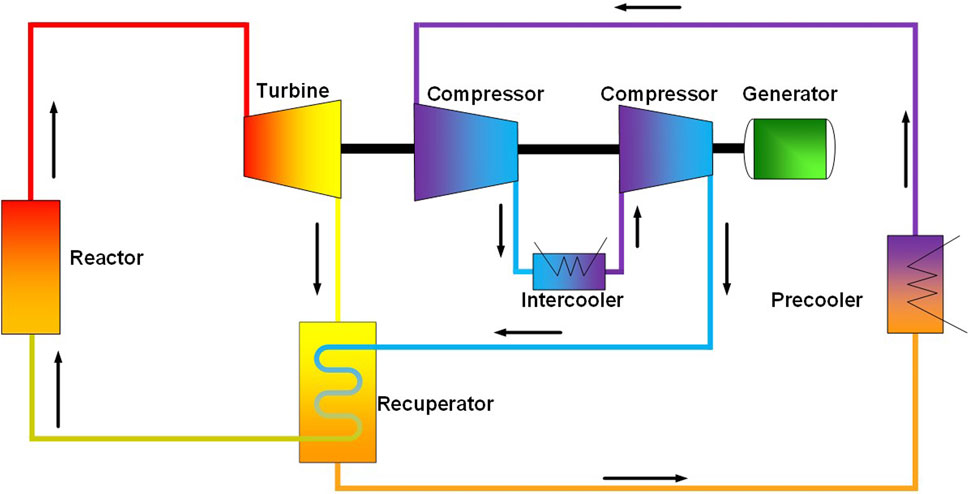
FIGURE 1. Main system of the micro gas-cooled reactor.
As depicted in Figure 2, a reactor core with a designed thermal power of 5MWth, consists of 60 fuel bricks, an inner reflector assembly, an outer reflector, a core barrel, and 12 control drums. Graphite serves as both the neutron moderator and the fuel structure, making up the primary material of the fuel bricks, reflectors, and control drums. The nuclear fuel pellets are sintered from silicon carbide and coated fuel particles TRISO (with a design temperature limit of 1,600°C), and insert into the brick holes as the fuel rods. The coolant channels are uniformly distributed within the fuel blocks as holes.

FIGURE 2. Schematic figure of reactor structure: (A) fuel brick, (B) lateral layout and (C) axial layout.
The core has a total radial diameter (to the outer edge of the reflector) of 210 cm and a total axial length of 220 cm. The active zone has an equivalent diameter of 131 cm and a length of 164 cm.
The Modelica model of the micro gas-cooled reactor system was established, as illustrated in Figure 3A. The model comprises five subsystems, with data exchange facilitated by the Modelica interface. The five subsystems are described as follows.
(1) Reactor system. The core heat generated by the reactor system serves as the energy source for the Brayton cycle. The reactor system emphasizes core reactivity, nuclear power, thermal-hydraulics, decay heat power, and residual heat removal power. The system includes point reactor, decay heat power, and thermal-hydraulic models.
(2) Heat engine system. The heat engine system focuses on the Brayton cycle to facilitate heat-work conversion. The system encompasses models of turbines, compressors, regenerators, precoolers, intercoolers, and pipelines.
(3) Heat sink system. The heat sink system supplies the cold source for the precooler and intercooler in the heat engine system, and is simply implemented using a mass inlet boundary.
(4) Electrical system. The electrical system converts rotational kinetic energy from the heat engine system into electrical energy and is simply realized by employing a given load.
(5) Control system. The control system concentrates on power operation and heat sink control.
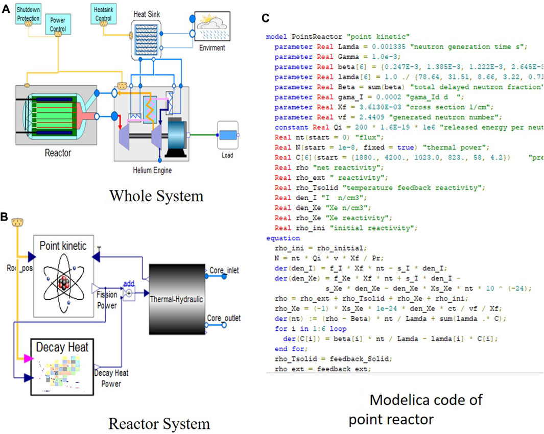
FIGURE 3. Modelica modeling of the micro gas-cooled reactor system: (A) whole system, (B) reactor system and (C) modelica code of point reactor.
The models of the reactor system, heat engine system and control system will be discussed detail below.
The Modelica model of the reactor system is depicted in Figure 3B, encompassing the point reactor, decay heat, and thermal-hydraulic models. The decay heat model is implemented by invoking external C functions using the external function interface in MWorks. The helium inlet and outlet within the reactor system are connected to the helium outlet and inlet in the heat engine system, respectively.
The reactor neutron model is based on point reactor neutron dynamics. The three-dimensional (3-D) effect of neutron space dynamics is neglected, with the neutron flux distribution fixed in space and varying only with time. The equations are listed as follows:
Here, N represents the average neutron density, Λ denotes the neutron generation time, β signifies the total delayed neutron fraction, βi indicates the delayed neutron fraction of group i, Ci is the precursor concentration of the delayed neutron of group i, λi is the decay constant of the delayed neutron of group i, and ρ stands for the net reactivity. The initial reactivity (ρini), temperature reactivity (ρT), xenon reactivity (ρXe), and external reactivity (ρext) introduced by control drums are considered in the model.
“When the net reactivity ρ equals zero, both the quantity of neutrons and the fission power within the reactor core remain steady, thus enabling the chain reaction to sustain itself. This situation is termed the “critical state.” If ρ falls below zero, the neutron count decreases over time, and the chain reaction cannot self- sustain, leading to the “subcritical state.” Conversely, when ρ is above zero, the neutron quantity exponentially increases over time, putting the reactor into the “supercritical state.”
The fuel temperature coefficient αT is defined as the change in reactivity per degree change in the fuel temperature, which is of crucial for reactor stability. A reactor with negative αT is inherently stable to changes in its temperature and thermal power, while a reactor with positive αT is inherently unstable. The high-temperature gas-cooled reactor (HTGR) core in this conceptual design possesses a substantially negative fuel temperature coefficient, roughly around -4pcm/°C.
Xenon-135 is a product of U-235 fission and has a very large neutron capture cross-section, which introduce negative reactivity ρXe. It decays radioactively with a half-life of 9.1 h. Little Xe-135 results directly from fission, but most comes from the decay chain, Te-135 to I-135 (β–decay, 6.6 h) to Xenon-135. The instantaneous production rate of xenon-135 is dependent on the iodine-135 concentration and, therefore, on the neutron flux history. On the other hand, the destruction rate of xenon-135 is dependent on the instantaneous local neutron flux.
In the formulas, NI and NXe represent the concentrations of I-131 and Xe-135, respectively. γI and γXe are the yields of I and Xe per fission event, ∑f is the macroscopic fission cross-section of the reactor core, λI and λXe are the decay constants of I and Xe, respectively, σaXe is the microscopic capture cross-section of Xe, and ϕ is the neutron flux. Ct is the reactivity adjustment factor, and is the average number of neutrons produced per fission event.
From a mathematical perspective, the aforementioned equations for the point reactor are Differential-Algebraic Equations. These can be readily represented using the Modelica language. As illustrated in Figure 3C, the code implementation for the point kinetic reactor is rather straightforward.
Due to the symmetry, one-sixth of the entire reactor is selected for the thermal-hydraulic (T-H) model, as illustrated in Figure 4. This includes the fuel bricks, inlet and outlet plenums, and thermal components (reflectors, core barrel, and pressure vessel). As the primary material of the control drums is the same as that of the reflectors, they are simply considered identical and merged into the reflector component in the T-H modeling.
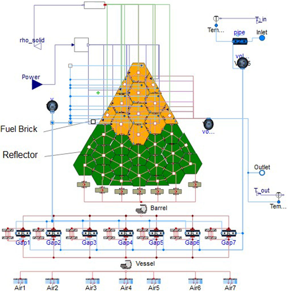
FIGURE 4. Modelica model of the reactor thermal-hydraulic.
Since a significant amount of graphite, which is a thermal conductor, is present inside the core, it is crucial to model the heat conduction phenomenon in the solid core regions. In reality, gaps may exist between the bricks, deteriorating heat transfer. In this preliminary work, the assumption of no gap is adopted, and heat conduction is ideally considered between the fuel bricks, reflectors, and barrel.
As the nuclear power in different fuel bricks is nonuniform, the heat transfer phenomenon in the reactor region exhibits 3-D behavior, which should be taken into account in modeling and simulation. In this paper, a T-H model with coarse 3-D nodalization is established using the lumped parameter method.
The nodalization of fuel region is illustrated in Figure 5. There are 12 lateral nodes, with each one representing a brick, while the fuel bricks are sectioned into 8 axial segments. This configuration results in a total of 96 blocks, with each block comprising a fuel rod, a solid fuel block and a flow segment. Every fuel block possesses a fuel rod that generates nuclear heat power, conducts thermal energy to adjacent solid fuel blocks both vertically and horizontally, and dissipates heat energy into the internal gas segment through convection. The thermal-hydraulic (T-H) modeling for the reflector and vessel is both similar to and more straightforward than the fuel region’s modeling, also incorporating heat conduction. The reflector region consists of 144 nodes in total, with 18 lateral nodes and 8 axial segments.
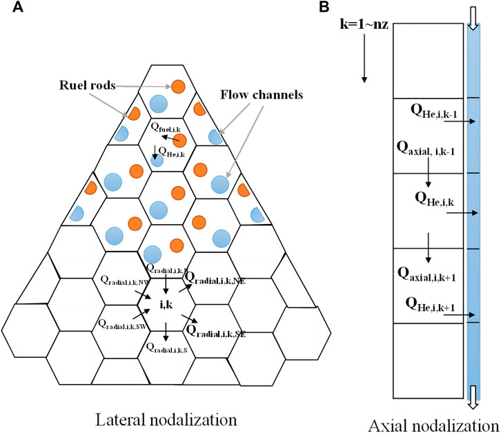
FIGURE 5. Core nodalization: (A) lateral nodalization and (B) axial nodalization.
The energy conservation equations of the solid fuel region are as follows.
In these equations, i and k represent the coordinates; Vf denotes the segment volume; ρf stands for the density; Cp is the specific heat capacity; Tblock is the brick temperature; Qfuel refers to the heat release from the fuel rods; QHe signifies the output heat convection energy with helium; Qradial indicates the heat conduction energy with the radial segments of the surrounding fuel assembly; and Qaxial represents the heat conduction energy with the axial segments within the fuel assembly. Qnuclear refers to the input nuclear power.
Since there is no cross flow between flow channels, a flow channel can be modeled as a pipe using the Modelica standard library. Helium compression is considered, and heat convection is calculated as follows:
In these equations, QHe represents the heat convection energy, hHe is the heat convection coefficient, AHe denotes the heat transfer area, THe stands for the helium temperature, λHe is the conductivity, Cp,He refers to the specific heat capacity, Dchannel signifies the channel diameter, mHe indicates the helium mass flow rate, l is the channel length, NuHe is the Nusselt number, PrHe is the Prandtl number, ReHe is the Reynolds number, and Recritical is the critical Reynolds number between laminar and turbulent flow.
For the gap between the barrel and vessel, heat radiation is assumed to be the sole heat transfer process. For external vessel cooling, air convection is simply modeled by setting a fixed convection heat transfer coefficient.
As depicted in Figure 6, the heat engine system employs a direct Brayton cycle to achieve heat-work conversion, providing a highly efficient method of generating power. The system comprises several key components, including a turbine, compressors, a recuperator, a precooler, an intercooler, and pipes. These components work together to ensure the efficient transfer of thermal energy from the reactor core to the working medium, which in this case is helium. The modeling of compressor and turbine was carried out by using a open source Modelica library ThemoCycle (Quoilin et al., 2014).

FIGURE 6. Modelica model of the heat engine system.
High-pressure helium flows through the reactor core, where it absorbs heat generated by the nuclear reactions. The heated helium then enters the turbine, where it expands and performs work, driving the main shaft to rotate. The rotation of the main shaft powers the compressors, which are responsible for compressing the helium to increase its pressure.
The relatively high-temperature helium from the turbine passes through the lower pressure side of the recuperator. In the recuperator, the heated helium transfers its thermal energy to the cooler, high-pressure helium coming from the high-pressure compressor. This heat exchange process improves the overall efficiency of the cycle by recovering and reusing thermal energy.
Following the recuperator, the helium enters the precooler, where its temperature is further reduced by exchanging heat with a cooling medium, typically water. The cooled helium then enters the low-pressure compressor, where it is compressed, increasing its pressure but maintaining a lower temperature.
The low-temperature, low-pressure helium is then sequentially compressed by the low and high compressors, which are connected by the intercooler. The intercooler plays a crucial role in maintaining the efficiency of the compression process by removing heat generated during compression.
Once compressed, the helium passes through the higher pressure side of the recuperator, where its temperature rises again to approximately that at the turbine outlet. This increase in temperature is achieved by absorbing heat from the high-temperature helium exiting the turbine.
Finally, the heated helium flows back into the reactor core, where it absorbs more heat generated by nuclear reactions, and the thermal cycle process repeats. This continuous process allows the heat engine system to generate power efficiently, capitalizing on the unique properties of helium as a working medium in the Brayton cycle.
It is assumed that the helium flow remains stable within the turbine and compressor, and the process is adiabatic. The ThermoPower library is utilized to create the models for both the turbine and compressor. Characteristic curves, commonly employed in practical engineering applications, are used to represent the working process (Fernández-Villacé and Paniagua, 2010).
The control system, in its current research stage, comprises power operation control and heat sink control, as depicted in Figure 7. The power operation control manages the movement of control drums in the reactor system based on monitored power and reactivity levels. The heat sink control, on the other hand, regulates the helium flow rate in the precooler and intercooler within the heat sink system according to the helium temperature. The control system enables the analysis of the coupling and compatibility between the reactor system and the heat engine system. Additionally, it can be used to explore various operation modes.
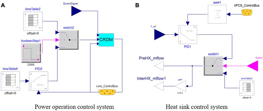
FIGURE 7. Modelica model of the control system: (A) power operation control and (B) heat sink control.
The nodalization of the Modelica reactor core modeling was rather coarse. This type of modeling approach is referred to as the lumped parameter modeling method (Bejan and Kraus, 2003), which is typically employed in system simulations to examine the system’s dynamic performance rather than analyzing the detailed performance of individual equipment. When compared to high-fidelity simulations such as CFD modeling, the lumped parameter model runs more quickly but inevitably sacrifices calculation accuracy. To assess the simulation accuracy of the lumped parameter modeling, a comparison with a high-fidelity CFD simulation was conducted.
A 3-D thermal model of the active zone in the reactor core is conducted using ANSYS CFX 2020. Taking symmetry into account, the calculation area was 1/12 of the entire reactor core, with detailed simulations conducted for the reactor fuel rods, fuel bricks, reflector bricks, and helium flow channels, as shown in Figure 8A. The total number of grids was 2.77 million.
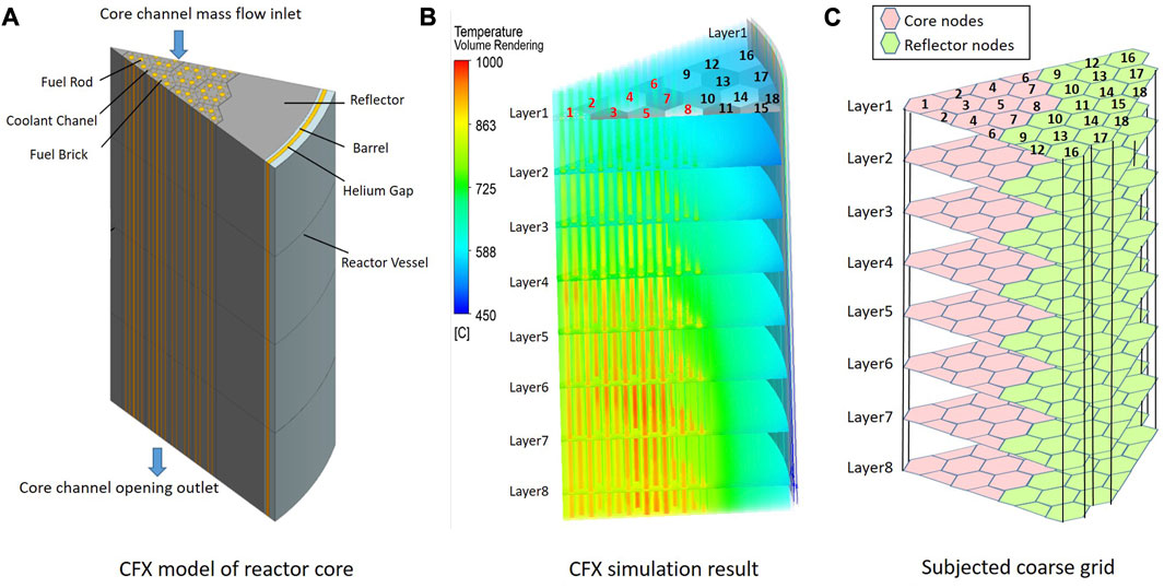
FIGURE 8. CFD simulation: (A) CFX modeling of reactor, (B) CFX simulation result and (C) subjected coarse grid.
The CFD (Computational Fluid Dynamics) calculation considers the following assumptions: The core thermal power is 5MW, with the axial power distribution being a cosine distribution, and the radial center component having the highest power. The helium gas inlet temperature is 440°C, with a flow rate of 2.8 kg/s. The core outlet uses an opening boundary, with a reference pressure of 1.6 MPa.
The CFD calculation yielded a detailed temperature field, as shown in Figure 8B. To validate the lumped parameter program in Modelica, the CFD calculation results were subjected to a coarse grid averaging process. The coarse grid was consistent with Modelica’s nodal grid, as illustrated in Figure 8C.
The temperature deviations between the system model and the CFD model calculation results are shown in Table 1. The system model is divided into 8 layers axially, and Table 1 presents the deviations for the even-numbered layers at each node. Overall, the system model shows good agreement with the CFD fine model calculation results, exhibiting similar trends. The maximum temperature deviation for the fuel rods is 18.7°C, with a relative deviation of 1.3%; the maximum temperature deviation for the graphite blocks is 15.9°C, with a relative deviation of 1.3%; and the maximum temperature deviation for the reflector layer is 11.3°C, with a relative deviation of 1.9%. As a system simulation model, the Modelica model maintains an acceptable level of calculation result accuracy while ensuring computational speed.
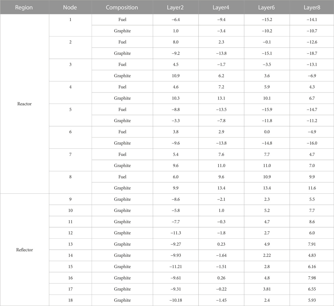
TABLE 1. Temperature deviations between a CFD simulation and the Modelica modeling (°C).
Drawing upon the aforementioned theories and Modelica models, two simulations of the micro gas-cooled reactor design were conducted. One simulation focused on an accident of anticipated transients without scram (ATWS), while the other examined normal reactor-engine load-following operation.
The ATWS accident scenario is defined as a situation in which the heat engines shut down and the helium flow rate drops to zero, with all the control drums and shutdown control rod fail to move and introduce more negative reactivity. In such an event, heat generated by the reactor core would transfer to the outer wall of the reactor pressure vessel and dissipate through passive air cooling. For this simulation, it was assumed that the accident occurred after the reactor had been operating at full power for 72 h. The results of the simulation, including the various reactivity, power level, core temperature, are depicted in Figures 9, 10, 11.
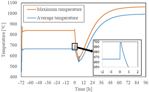
FIGURE 9. Fuel temperature.
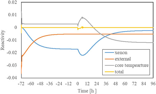
FIGURE 10. Core reactivity of ATWS accident.
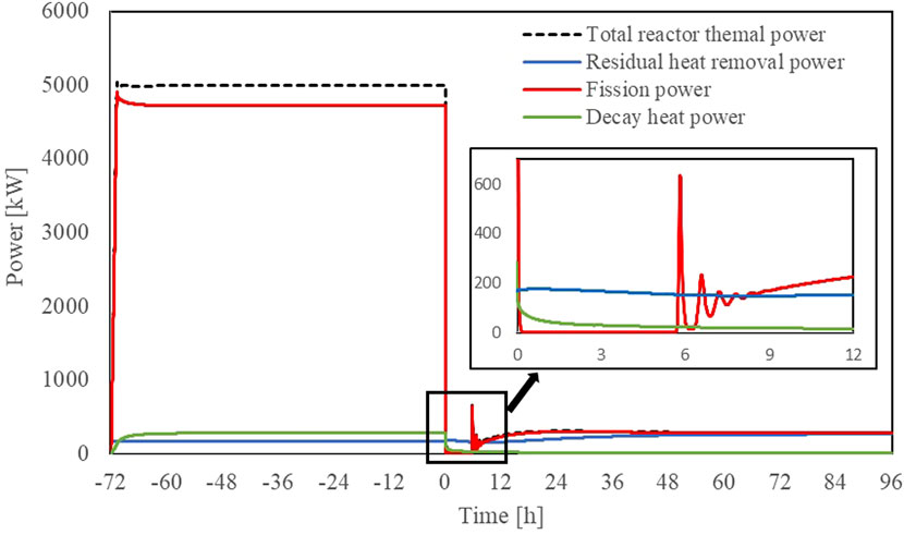
FIGURE 11. Reactor power and residual heat removal power.
As a result of the coolant flow loss, the core’s average temperature rapidly escalated, as illustrated in Figure 9. This surge incited a substantial increase in negative reactivity, subsequently causing a decrease in the core’s overall reactivity. As a consequence, the core entered a subcritical state, and the fission power drastically fell to zero. This abrupt reduction in power prompted a surge in negative reactivity due to xenon poisoning, leading to a continued decrease in the reactor’s overall reactivity. Simultaneously, the core began to cool slowly due to the operation of the passive heat removal system.
At 5.7 h, the positive reactivity introduced by the decrease of fuel temperature surpassed the negative reactivity from xenon poisoning, causing the reactor to return to critical. With the negative reactivity feedback from fuel temperature and continuous heat removal, the reactor experienced about 3 h of power fluctuations before gradually stabilizing at 8 h. During this oscillation process, the peak fission power was 658 kW. Since the fuel has a large heat capacity, significant temperature fluctuations did not occur. Afterward, as xenon poisoning gradually diminished and the heat removal system continued to work, about 72 h after the accident, the core power stabilized. At this point, the average core temperature was approximately 992°C, and the fission power was 260 kW which was comparable to the heat removal power.
The maximum fuel temperature during the accident was about 1,060°C (The fuel and graphite is not separated, and the real maximum fuel temperature will be higher than the simulated value), which is lower than the design limit temperature (1,600°C) (Rohbeck and Xiao, 2016). This indicates that the reactor can achieve shutdown solely through the negative reactivity resulting from the increase in core temperature, demonstrating its excellent inherent safety. In fact, a similar accident experiment was conducted on the high temperature gas-cooled reactor-test module (HTR-10) at Tsinghua University in 2003 (Gou et al., 2018), where the reactor shutdown was automatically achieved through the same mechanism. This further validates the safety of the fuel and core in the micro gas-cooled reactor design.
Assuming that the electricity load varies over time and fluctuates periodically, the load-following operation of the micro gas-cooled reactor system was simulated. The fluctuation period was set to 24 h, consisting of peak periods, steady periods, and low periods, as shown in Figure 12. The reactor nuclear power and net output power were adjusted by controlling the helium inventory (or pressure) and the control drum position.

FIGURE 12. Nuclear power and output power.
During the load-following operation, the reactor successfully adjusts its nuclear power output to meet the varying demand for electricity, with the nuclear power output and net output power changing periodically and synchronously. Specifically, during the peak period, the reactor’s nuclear power and net output power are 4.10 MW and 1.37 MW, respectively. Meanwhile, during the low period, the nuclear power and net output power decrease to 2.10 MW and 0.69 MW, respectively. The electric power generation efficiency, defined as the ratio of net output power to nuclear power, remains stable at approximately 33%, as depicted in Figure 13. This shows that the micro gas-cooled reactor system is capable of efficiently responding to varying electricity demand, and can provide a stable and reliable power source.

FIGURE 13. Power generation efficiency.
As shown in Figure 14B), the helium temperature at the core inlet and outlet is approximately 435°C and 750°C, respectively, and both change periodically with a small fluctuation of around ± 3°C.

FIGURE 14. Pressure and temperature during load following transient: (A) core outlet pressure and (B) temperature at core inlet and outlet.
As depicted in Figure 15, the negative temperature reactivity remains stable due to the constant core temperature, while the negative xenon reactivity oscillates periodically due to changes in xenon concentration resulting from the fluctuating reactor power. Therefore, the external reactivity introduced by control drums also changes periodically to maintain criticality in the reactor.
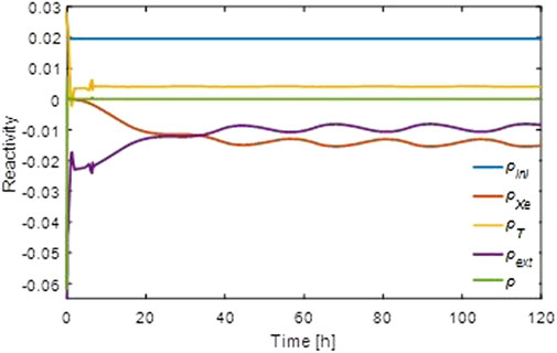
FIGURE 15. Core reactivity of load following scenario.
Micro-reactors exhibit a high degree of system integration, with various system functions closely coupled and mutually constrained, posing complexity challenges that traditional discipline-specific decoupled design patterns find difficult to address. The Modelica language facilitates swift modeling of cross-disciplinary systems and has gained widespread use in the research and development of complex equipment across industries such as aviation, aerospace, automotive, and energy. However, its application within the nuclear industry remains relatively limited. As a pioneering attempt, this study employs Modelica to develop models for several subsystems, encompassing the reactor, energy conversion system, and control system. The accuracy of the reactor core model was affirmed by high-fidelity CFD simulation results, showcasing good agreement and fulfilling system simulation requirements.
Further investigations were then conducted on the safety and operational characteristics of the whole system. The results indicate that the reactor possesses excellent inherent safety even during an ATWS accident, with reactor shutdown achieved via negative reactivity from the increase in core temperature, and the fuels remaining undamaged due to decay heat removal via passive air cooling from the exterior of the reactor pressure vessel. The maximum fuel temperature during the accident is about 1,060°C, which is lower than the design limit temperature (1,600°C). Additionally, the reactor exhibits strong load-following performance, with simple adjustments to the helium inventory (or pressure) and control drum position maintaining constant core temperature and power generation efficiency at approximately 33%.
This study’s research methodology lays a solid foundation for the full-system modeling and simulation of gas-cooled micro-reactors, while also offering valuable insights for the system modeling and simulation of other types of reactors. Currently, the deployment of Modelica language in Chinese industries is growing extensively. The China Nuclear Power Engineering Company is keen on leveraging the generic model libraries established in the industry to enhance swift iterations in model design and facilitate the creation of digital twins for future nuclear energy models.
The original contributions presented in the study are included in the article/Supplementary material, further inquiries can be directed to the corresponding author.
HM proposed conception and design of the study, developed program code and wrote and edited the first draft of the manuscript. YL did simulation and plot the illustrations. YZ did code verification. SD supervised the findings of this work. JW revised draft of the manuscript. WM proposed the methodology and gave the writing review. All authors contributed to the article and approved the submitted version.
HZ, YL, YZ, JW, and SD were employed by China Nuclear Power Engineering Co., Ltd.
The remaining author declares that the research was conducted in the absence of any commercial or financial relationships that could be construed as a potential conflict of interest.
All claims expressed in this article are solely those of the authors and do not necessarily represent those of their affiliated organizations, or those of the publisher, the editors and the reviewers. Any product that may be evaluated in this article, or claim that may be made by its manufacturer, is not guaranteed or endorsed by the publisher.
Bonan, Z., Faren, Q., Tao, X., Yang, L., and Wei, W. (2020). Model based development method of manned spacecraft: research and practice. Acta Aeronaut. Astronaut. Sin. 41 (7), 23967. doi:10.7527/s1000-6893.2020.23967
Fernández-Villacé, V., and Paniagua, G. (2010). “Simulation of a combined cycle for high-speed propulsion,” in Proceeding of the AIAA Aerosp. Sci. Meet. Incl. New Horizons Forum Aerosp. Expo. Paper presented at the 48th. doi:10.2514/6.2010-1125
Frick, K., and Bragg-Sitton, S. (2021). Development of the NuScale power module in the INL modelica ecosystem. Nucl. Technol. 207 (4), 521–542. doi:10.1080/00295450.2020.1781497
Gou, F., Liu, Y., Chen, F.-B., and Dong, Y.-J. (2018). Thermal behavior of the HTR-10 under combined PLOFC and ATWS condition initiated by unscrammed control rod withdrawal. Nucl. Sci. Tech. 29 (9), 123–129. doi:10.1007/s41365-018-0472-3
Greenwood, M. S., Betzler, B. R., and Qualls, A. L. (2018). Dynamic system models for informing licensing and safeguards investigations of molten salt reactors. Available at: https://www.osti.gov/servlets/purl/1456790.
Greenwood, M. S. (2017). TRANSFORM—TRANsient simulation framework of reconfigurable models. Oak Ridge National Laboratory. Available at: https://github.com/ORNL Modelica/TRANSFORM-Library.
Hale, R., Fugate, D., Cetiner, M., Ball, S., Qualls, A., and Batteh, J. (2015). Update on ORNL TRANSFORM tool: preliminary architecture/modules for high-temperature gas-cooled reactor concepts and update on ALMR control (ORNL/SPR-2015/367). Oak Ridge National Laboratory.
Huang, Y., Zeng, X., and Ding, J. (2021). Simulation model architecture and concept validation for thermal hydraulic characteristics based on modelica. Nucl. Power Eng. 42 (1), 1–7. doi:10.13832/j.jnpe.2021.01.0001
Liang, Y., Zhang, H., Wang, L., Li, Y., Yuan, Y., Wang, J., et al. (2022). The application of modelica simulation technology in micro gas-cooled reactor. Nucl. Power Eng. 02, 152–159. doi:10.13832/j.jnpe.2022.02.0152
Liu, C., Chen, L., Ding, J., and Shangguan, D. (2022). Modeling of satellite constellation in modelica and a PHM system framework driven by model data hybrid. Electronics 11, 2155. doi:10.3390/electronics11142155
Quoilin, S., Desideri, A., Wronski, J., Bell, I., and Lemort, V. (2014). “ThermoCycle: A modelica library for the simulation of thermodynamic systems,” in Proceedings of the 10th International Modelica Conference (Linköping University Electronic Press), 683–692. doi:10.3384/ECP14096683
Rabiti, C., Epiney, A., Talbot, P., Kim, J. S., Bragg-Sitton, S., Alfonsi, A., et al. (2017). Status report on modelling and simulation capabilities for nuclear-renewable hybrid energy systems (No. INL/EXT-17-43441. Idaho Falls, ID: Idaho National Lab. (INL); Oak Ridge, TN: Oak Ridge National Lab. (ORNL); Argonne, IL: Argonne National Lab. (ANL). doi:10.2172/1408526
Rader, J. D., Smith, M. B., Greenwood, M. S., and Harrison, T. (2019). Nuclear thermal propulsion dynamic modeling with modelica. Available at: https://www.osti.gov/servlets/purl/1543223.
Rohbeck, N., and Xiao, P. (2016). Evaluation of the mechanical performance of silicon carbide in TRISO fuel at high temperatures. Nuclear Engineering and Design, 306, 52–58. doi:10.1016/j.nucengdes.2016.05.040
Wang, Y., Zhou, F., Chen, L., Ding, J., Zhou, J., and Center, C. A. D. (2006). “Domain library preprocessing in MWorks—A platform for modeling and simulation of multi-domain physical systems based on modelica,” in Proceedings of the 5th International Modelica Conference, Vienna, Austria (Dr. Christian Kral), 733–740.
Yizhong, W., Fanli, Z., Liping, C., Jianwan, D., Jianjun, Z., and Center, C. A. D. (2006). “Domain library preprocessing in MWorks-a platform for modeling and simulation of multi-domain physical systems based on modelica,” in Proceedings of the 5th International Modelica Conference (Vienna, Austria: Dr. Christian Kral), 733–740.
Keywords: Modelica modeling, system simulation, micro gas cooled nuclear reactor, nuclear accident analysis, MBSE (model-based system engineering)
Citation: Zhang H, Li Y, Zhao Y, Wang J, Du S and Ma W (2023) Modeling and simulation of a micro gas-cooled nuclear reactor using Modelica. Front. Energy Res. 11:1206755. doi: 10.3389/fenrg.2023.1206755
Received: 16 April 2023; Accepted: 15 August 2023;
Published: 29 August 2023.
Edited by:
Yaoli Zhang, Xiamen University, ChinaReviewed by:
Wei Chunlin, Tsinghua University, ChinaCopyright © 2023 Zhang, Li, Zhao, Wang, Du and Ma. This is an open-access article distributed under the terms of the Creative Commons Attribution License (CC BY). The use, distribution or reproduction in other forums is permitted, provided the original author(s) and the copyright owner(s) are credited and that the original publication in this journal is cited, in accordance with accepted academic practice. No use, distribution or reproduction is permitted which does not comply with these terms.
*Correspondence: Huimin Zhang, emhtYm9uZEAxNjMuY29t
Disclaimer: All claims expressed in this article are solely those of the authors and do not necessarily represent those of their affiliated organizations, or those of the publisher, the editors and the reviewers. Any product that may be evaluated in this article or claim that may be made by its manufacturer is not guaranteed or endorsed by the publisher.
Research integrity at Frontiers
Learn more about the work of our research integrity team to safeguard the quality of each article we publish.