 Rutian Wang1
 Xiangyun Wen
 Xiuyun Wang
94% of researchers rate our articles as excellent or good
Learn more about the work of our research integrity team to safeguard the quality of each article we publish.
Find out more
ORIGINAL RESEARCH article
Front. Energy Res. , 12 July 2023
Sec. Sustainable Energy Systems
Volume 11 - 2023 | https://doi.org/10.3389/fenrg.2023.1206242
This article is part of the Research Topic Low Carbon Design, Manufacturing and Application of the Energy Storage System and Equipment View all 5 articles
In order to solve the contradiction between energy supply and carbon emissions, using P2G to combine oxy-fuel combustion power plant with gas turbines. According to the laws of mass conservation and energy conservation, carbon and oxygen elements are introduced into the model in the form of gases to construct an energy hub model for the carbon oxygen cycle system. To solve the problem of time imbalance between interconnected devices, a flexible operation mode using storage devices as connection hubs is proposed. Based on the constraints of the system’s operating mechanism, study the variation range of the operating range and establish an objective function with the optimal operating cost. Optimize the operation of the combined system, study the change interval of its operation range, and analyze the scheduling model under three different operation models. Low-Carbon economic model of combined system is established in regional integrated energy system. The results show that the basic carbon oxygen cycle model can save 9.14% economic cost and reduce 44.05% carbon emission. The carbon oxygen cycle capacity increasing mode can save 13.05% economic cost and reduce 59.91% carbon emission. Carbon and oxygen circulation system in improving renewable energy consumption and reducing carbon dioxide emissions is verified by an example.
Environmental pollution, climate warming and fossil energy crisis all over the world pose a serious threat to sustainable development. At the 21st United Nations Climate Change Conference, many countries signed the Paris Agreement. In response to the international call, governments of various countries have made their own low-carbon commitments (UNCC, 2016). China announced at the 75th session of the UN General Assembly that it would enhance national independent contribution. It will strive to reach the peak of carbon dioxide emissions by 2030 and achieve carbon neutrality by 2060. Electricity production is one of the main sources of greenhouse gas emissions, which is facing huge pressure to reduce carbon emissions. Integrated energy system has obvious potential for Low-Carbon emission reduction, which integrates and optimizes electricity, gas, heat and other energy sources(Wang et al., 2020; Hua et al., 2020). Integrated energy system integrates electricity, gas and heat, and forms the integration of energy production, supply and marketing, which has become a research hotspot in the field of international energy (Gu et al., 2017; Wang et al., 2019).
Energy crisis and other issues have accelerated the application and promotion of regional integrated energy systems (RIES). RIES research is more suitable for China’s national conditions. The region is generally recognized as a region, a city, a town, etc. The concept of energy Internet (EI) is proposed (Dong and Zhao, 2014), which is conducive to the adjustment of energy structure and provides a new way to solve the problem of the acceptance of renewable energy. However, wind power generation has strong random volatility and typical anti-peak shaving characteristics, which has an adverse effect on the consumption of renewable energy (Lu et al., 2019). In 2010, the Fraunhofer Research Center in Germany put forward the concept of “electricity to gas” for the first time, which is expected to solve the problems of wind abandonment and energy storage (Energy Resource Guide, 2010). In 2003, the Swiss Federal Institute of Technology Zurich carried out research on energy planning projects (Favre-Perrod, 2005), analyzing the complementary advantages of multiple energy systems from various angles. And the idea of energy hub (EH) was first proposed in the literature (Geidl, 2007). In literature (Wang et al., 2017), an electric gas coupling link with EH as the core is constructed to study the interaction between electric power and natural gas system. Literature (Zhang, 2015) proposes an EH model with multiple energy systems, which represents the coupling between various energy infrastructures. It is used to supply electric power, natural gas and thermal loads. But in the above research, EH is only limited to the coupling of electricity, gas and thermal energy. The model of input and output transmitted in the form of gas energy flow is not considered and the source and recovery of gas are ignored. There are problems such as extra investment and energy loss.
In order to reduce the intensity of carbon emissions and alleviate climate change, carbon capture and encapsulation technology is an effective way, which has received extensive attention worldwide. Literatures (Viebahn et al., 2015; Viebahn et al., 2014) evaluate the feasibility of carbon capture and storage technologies in India and China respectively. Carbon capture technology mainly includes post-combustion capture technology, pre-combustion capture technology and oxy-fuel combustion technology. Among them, oxy-fuel combustion technology has many advantages and has become one of the technologies with great prospects (Ghorbani et al., 2018). The research on carbon capture technology is increasing, and the utilization of carbon dioxide has become a hot research field. Literature (Viklund and Karlsson, 2015) analyzes the relationship between waste heat used in energy system and carbon dioxide emissions. Literature (Karjunen et al., 2017) evaluates different implementation strategies of CO2 utilization system. Literature (Zhou et al., 2018) proposes power to gas (P2G) and carbon capture power plants as a unified system, carbon capture power plants provide raw material CO2 for P2G, and establishes a coordinated optimization model. Literature (Yang, 2019) proposes the concept of a combined system of P2G and gas turbine, which converts CO2 into gas-fired power plant (GFPP) fuel, and establishes a model of the GFPP-P2G combined system. Literature (Cui et al., 2020) proposes to introduce oxy-fuel combustion technology into the electricity-gas-heat RIES, and establishes a low-carbon model of P2G and oxy-fuel combustion plant (OFCP). The above research proves that the combined model can better improve the level of carbon utilization. However, the utilization of O2 in P2G technology and the incomplete absorption of OFCP are not considered, which causes time imbalance between systems, and further research is needed.
In response to the above problems, this article considers the gas energy flow, gas source and recovery problems in the traditional EH. An innovative energy cycle model for oxy-fuel combustion and power to gas is proposed, avoiding unnecessary energy loss and additional investment. And a new mathematical model of combined system is established from the point of view of amount of substance. To solve the problem of unequal time between interconnected devices, the flexible operation mode with storage devices as the connection hub is proposed. In Section 2, the interconnection of OFCP and P2G forms an energy circulation. In Section 3, construct the EH model of the OFCP-P2G-GFPP combination system, and introduce carbon and oxygen into the model in the form of gas. In Section 4, the power gas regional integrated energy system scheduling model based on the interconnection of P2G and OFCP is established. In Section 5, an example is given to verify the low-carbon and economic performance of the proposed model. In Section 6, draw the conclusion.
At present, the carbon emission of power industry mainly comes from coal-fired power plants, which leads to the contradiction between energy supply and carbon emission. This article mainly conducts related research on reducing carbon emissions in terms of transformation technology. Use P2G technology to combine OFCP with GFPP. The basic idea of joint operation of OFCP-P2G-GFPP system is shown in Figure 1.
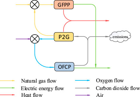
FIGURE 1. System model of OFCP-P2G-GFPP.
P2G technology uses electric energy to hydrolyze to produce H2 and O2. H2 reacts with CO2 to generate CH4, which is transported to GFPP through natural gas pipeline. O2 is transmitted to OFCP, and high-concentration O2 is used instead of air to achieve the purpose of combustion and obtain high purity CO2 stream. After further compression and purification, CO2 can be captured and stored, and returned to the P2G equipment as a raw material. The output power of GFPP and OFCP supplies power for the power load. The heat released in the process of CH4 generation and the high temperature flue gas discharged by GFPP can provide heat energy for the thermal load. Thus, energy can be locked in the annular OFCP-P2G-GFPP combined system to achieve energy recycling. It can not only effectively reduce CO2 emissions, but also reduce the operating cost of the system, which can realize low-carbon power generation.
In RIES, the thermal power units are transformed into low-carbon units. OFCP is mainly composed of air separation unit (ASU), compression purification unit (CPU) and oxygen-enriched boilers. The energy consumption of ASU and CPU is provided by thermal power plant. The conversion energy consumption of P2G is provided by renewable energy, which provides an effective way for wind energy consumption. The specific energy flow relationship among units is shown in Figure 2.
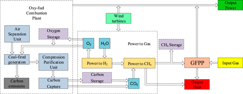
FIGURE 2. Energy flow diagram of regional integrated energy system.
P2G technology can improve the capacity of wind power absorption and provide a new way for the use of renewable energy. It converts the remaining wind energy into natural gas, which is transmitted to GFPP for the production of electric energy and heat energy. In order to solve the problem of time imbalance between P2G and GFPP, gas storage equipment can be added. And the temporary surplus natural gas will be collected into the gas storage equipment for storage. P2G recycles CO2 captured by OFCP, but only when there is abandoned air in the system, can P2G start to produce CH4. While OFCP always produces by-product CO2 during operation. In order to solve the problem of time inequality between the two, carbon storage equipment will be added to the system, which can save the cost of CO2 packaging and the raw material cost of P2G purchasing high-purity CO2. On the other hand, ASU realizes the separation of oxygen from air and supplies it to thermal power units. If ASU produces too much oxygen, it can only increase the output of the thermal power unit, that is to say, the power supply is determined by oxygen. In order to avoid this phenomenon, the O2 produced by P2G is liquefied under the action of cryogenic pump and transported to the liquid oxygen tank of OFCP for storage. When using O2, a vaporizer can be used to volatilize liquid oxygen into gas. The increase of energy storage equipment can effectively reduce the operation cost and unnecessary energy loss of the system. And the economic benefits and low-carbon operation have been improved, reflecting the advantages of multi-energy system interconnection.
EH is used as coupling element in RIES. Considering the energy source and Low-Carbon emission of P2G, a new EH model is established, and the transfer form of gas energy flow is introduced into the EH model. The new EH is embodied in the basic model of the OFCP-P2G-GFPP system, as shown in Figure 3.
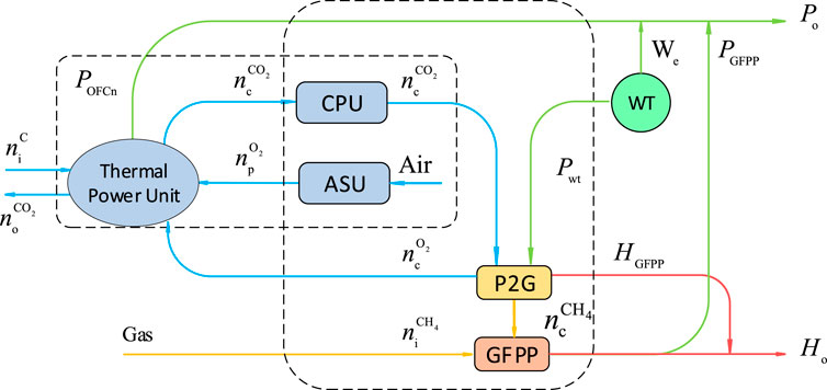
FIGURE 3. Simplified energy flow diagram of OFCP-P2G-GFPP system.
According to the law of conservation of mass and the law of conservation of energy, the OFCP-P2G-GFPP combined system model can be established. Among them, the variables P and H are the electric energy and heat energy transmitted by the system, and the unit is MW. W stands for renewable energy, n stands for the number of substances in each gas medium, the unit is mol. In the parameter subscript, i and o are the input and output of the combined system, c is the variable internally converted by the EH, p is the energy produced by each unit and equipment, and the parameter is the gas type.
According to the law of conservation of mass, in OFCP and P2G equipment, the sum of the total amount of substances before reaction is equal to the sum of the amount of substances after reaction. Thermal power plant is the core part of OFCP. The amount of coal used for combustion
The chemical equations of the two reaction stages of P2G are shown in Eqs 2, 3. Under standard conditions, the stoichiometric number in the P2G total reaction equation can also reflect the relationship between the amounts of each gaseous substance, as shown in Eq. 4.
According to the simplified energy flow diagram of OFCP-P2G-GFPP system, it can be known from the law of conservation of energy that the main output of the OFCP system is the thermal power unit. The output electric energy of the unit is
Since P2G is a highly exothermic reaction, the heat generated by it can be transferred to the heating system. The heat value generated by the reaction per mole of CH4 is
Natural gas and P2G jointly provide energy for GFPP unit, and the unit performs work to convert natural gas into energy for utilization.
In the basic operation mode of the combined system, the law of conservation of mass is used to calculate CO2 emissions, as shown in Eq. 12.
The output power of the basic operation mode
Among them,
The output heat of the basic operation model
OFCP and P2G equipment are in the capacity increasing mode, as shown in Figure 4.
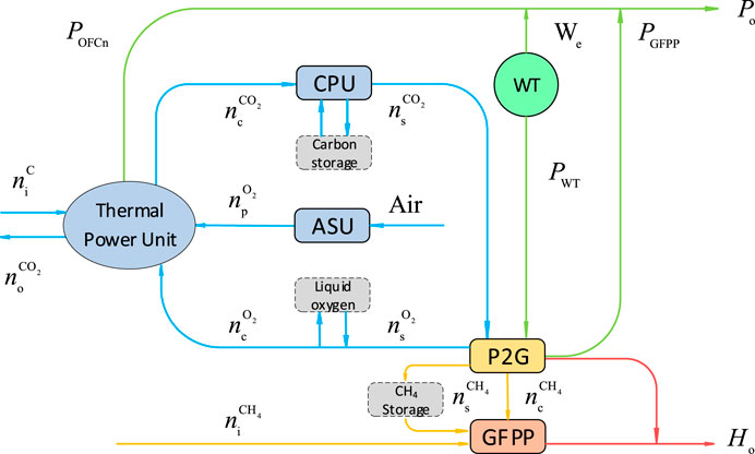
FIGURE 4. System energy flow diagram of OFCP-P2G-GFPP.
In order to solve the problem of time and space mismatch, carbon storage tank, liquid oxygen tank and gas storage tank are added to capacity increasing model. The total reaction stage of P2G still follows the law of conservation of mass, which can be expressed by Eq. 15 combined with the relationship between stoichiometry and the amount of substance.
In the capacity increasing operation mode of the combined system, the law of conservation of mass is used to calculate the CO2 emission.
Due to the investment in energy storage equipment, the carbon emissions are affected by the air in and out of the oxygen storage equipment and carbon storage equipment. From the mathematical model shown in Eq. 16, we can see that it can provide a way to reduce carbon emissions.
The output electric energy
From the mathematical model shown in Eq. 17, the output power of the system increases. The input of the liquid oxygen tank provides a convenient working environment for OFCP. The input of carbon storage tanks provides clean energy raw materials for P2G equipment. The investment in gas storage tanks provides efficient operation efficiency for GFPP.
Resolve and sum the output heat of the capacity-increasing operation model
From the mathematical model shown in Eq. 18, the output heat energy of the system increases. The input of gas storage tank has a great influence on the output of the thermal system, which can improve the heating performance of the system.
Based on the electricity-gas regional integrated energy system, the thermal power unit will be transformed into a low-carbon. And P2G is used to realize energy circulation, thus forming OFCP-P2G-GFPP regional integrated energy system. The operation mode of the combined system is determined by each sub module. The output energy is affected by input energy, renewable energy, energy storage equipment and operation constraints of each unit. It is more necessary to analyze the operation mechanism of OFCP-P2G-GFPP combined multi-energy system.
Minimize system operating costs
In the equation:
(1) Constraints of ASU output
In the inequality:
(2) Constraints of CPU output
In the inequality:
(3) Constraints of natural gas output
In the inequality:
(4) Constraints of P2G output
In the inequality:
(5) Constraints of gas storage device
The specific expressions of the gas storage device model are the balance conditions of gas storage capacity shown in Eqs 30–32, the limit constraints of gas storage capacity shown in inequalities Eq. 33, 34, and the input and output flow constraints shown in inequalities Eqs 36, 37,38.
In the equation:
After the system runs in a scheduling period, the total in and out of energy storage equipment is not counted. Restore it to the initial value to leave enough adjustment space for the next cycle:
In the constructed OFCP-P2G-GFPP regional integrated energy system, the node power balance conditions are shown in Eq. 40, and the constraint conditions of P2G wind curtailment are shown in Eq. 41 and 42.
In the equation:
The OFCP-P2G-GFPP system first needs to meet the power output constraints. On the one hand, the power output constraint is affected by the output of thermal power units and gas turbines, and there are upper and lower limits for the output power of the units, as shown in inequalities (43) and (44). On the other hand, it is restricted by the consumption of renewable energy, as shown in inequality (45).
Combining the output constraints under two different conditions, the operating range of the system is shown in Figure 5. Natural gas source provides energy for independent operation of gas turbine, and the output of the system is a linear curve passing through the origin. When the same natural gas energy is input, with the integration of OFCP and the consumption of renewable energy, the system operation curve gradually tends to be highly efficient. Under the system constraints, the power output range of the system increases, and the system operates flexibly within this range.
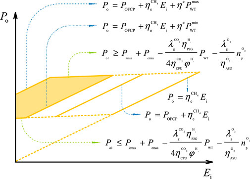
FIGURE 5. Schematic diagram of system power output range.
In addition, the OFCP-P2G-GFPP system also needs to meet the thermal power output constraints. Since the output power of the gas turbine has upper and lower limits, the output range of the gas turbine affects the thermal power output of the system, as shown in inequality (46). Secondly, the thermal power output of the system is also affected by the consumption of renewable energy, as shown in inequality (47).
The operating range of system thermal power can be obtained from the output constraint in the same way, as shown in Figure 6. The system inputs the same natural gas energy, and compared with the independent operation of the gas turbine, the range of the OFCP-P2G-GFPP system’s output heat energy is increased, and the flexibility of operation is improved.
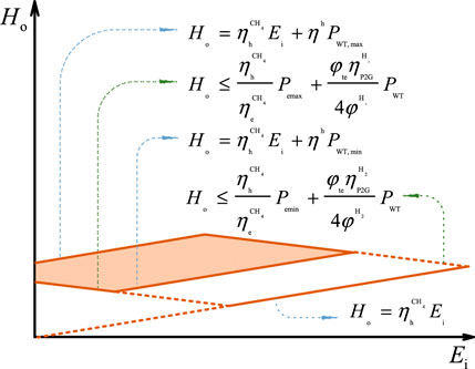
FIGURE 6. Schematic diagram of system heat energy output range.
Since the main concern is the carbon emission and wind curtailment of RIES, it is assumed that the gases are in standard temperature and pressure. If there are other gases state in actual operation, corresponding constraints can be added to the model. In order to simplify the dispatching model, only the combination of OFCP-P2G-GFPP system and renewable energy is considered, and other types of generating units are ignored. If there are other types of units in the actual scheduling, the corresponding constraints can be added to the model. In order to linearize the processing system, the minimum input power of unit equipment is ignored. Start stop constraints can be added in actual scheduling. The objective function is the optimal economic cost. Other objective functions can also be applied to this study. This will not affect the system of OFCP-P2G-GFPP.
There are no coupling components such as P2G devices in the discrete operation mode. There are no energy transmission and conversion between units, and they all operate independently. The dispatching model is shown in the following equation.
OFCP-P2G-GFPP direct energy transmission and conversion between units. At the same time, the conversion time shift is ignored, that is, the CO2 emitted by the OFCP is instantly converted into CH4 under the action of P2G. The energy flow parameters used in the basic operation model are shown in Figure 2, and the scheduling model is shown in the following equation.
In order to solve the problem of inequality between time and space, the capacity-increasing model adds storage equipment to the premise of the basic model. The scheduling model is shown in the following equation.
In this section, according to the different operating modes of the system, three cases are set, and then comparative analysis is carried out. Taking the economic cost of system operation as the optimal objective, the impact of carbon dioxide emissions and renewable energy acceptance capacity on the system is analyzed. Compare the separate operating units with the OFCP-P2G-GFPP combined system, and analyze the changes in the output of thermal power units and external natural gas. After comparing the differences between the basic mode and the capacity increasing mode of OFCP-P2G-GFPP combined system, the impacts of the system on CO2 emissions and renewable energy utilization are analyzed. Firstly, referring to the typical daily load in winter in reference (Yang, 2019), the typical parameters of facilities in OFCP-P2G-GFPP combined system are determined, and the scheduling period is 24 h. Secondly, the IPOPT solver based on the interior point method in the optimization software GAMS is used to optimize the solution.
There are many parameters in the model of OFCP-P2G-GFPP combined system. Typical values of carbon capture technology and oxy-fuel combustion technology are shown in literature (Cui et al., 2020)- (Chen et al., 2010). In the transformation process of P2G technology, the required physical quantities are shown in literature (Hoekman et al., 2010). and the constraints of each unit are shown in literature (Yang, 2019). In order to unify the parameter unit, according to the gas molar volume equation and the ideal gas equation of state, the parameter values are converted to standard values. Typical operation parameters of each unit are shown in Table 1.
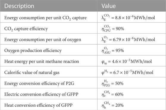
TABLE 1. Typical parameters of the system.
The common cost coefficients of thermal power units, natural gas sources and wind turbines are shown in literature (Jiang, 2018) and (Zeng et al., 2016), P2G operating cost coefficient is shown in literature (Guandalini et al., 2015), and the cost of energy storage equipment is shown in literature (Yang, 2019), (Touretzky et al., 2016) and (Wang et al., 2014). Same as above, the parameter values need to be converted uniformly. The typical cost coefficients are shown in Table 2.
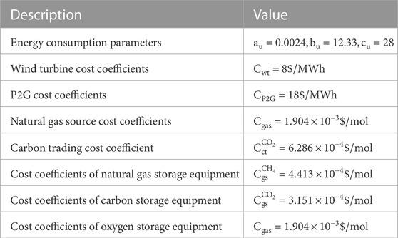
TABLE 2. Typical cost coefficients.
The typical daily load curve and the predicted output curve of wind farm in literature (Yang, 2019) are partially modified, as shown in Figure 7.
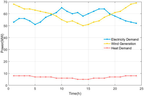
FIGURE 7. Electric load, thermal load and wind farm forecast output curve in each time period.
In order to study the characteristic relationship of OFCP-P2G-GFPP combined system, the objective function is to optimize the economic cost of operation. According to the difference of the introduction of P2G, this article sets the following three cases for comparative analysis.
Case 1 Ignore P2G technology, OFCP and GFPP run independently.
Case 2 Considering P2G technology, power-to-gas technology combines OFCP with gas turbines, which constitutes the basic scheduling model for the joint operation of OFCP-P2G-GFPP system.
Case 3 Considering P2G technology, on the premise of basic scheduling model of OFCP-P2G-GFPP system, add energy storage equipment with multiple gases. Then the capacity increase scheduling model of OFCP-P2G-GFPP system is constructed.
This article considers the operation of the system in the above three cases and analyzes the advantages of the OFCP-P2G-GFPP combined system. The specific costs are shown in Table 3.
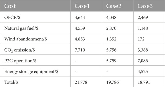
TABLE 3. System operating cost table.
Case 2 saves 1991$ in total cost compared with Case 1, which is 9.14%. The cost of carbon emission is significantly reduced, and the carbon dioxide emission is effectively improved. Case 3 saves 2986$ in total cost compared with Case 1, which is 13.05%. The cost of abandoned wind is greatly reduced, and the absorption effect and flexible operation ability of abandoned wind are effectively improved. It is proved that the joint operation of OFCP-P2G-GFPP system is effective in low-carbon economic dispatch. Case 3 saves 995$ in total cost compared to Case 2. In order to absorb more abandoned wind, the output of P2G is increased, but the energy storage equipment improves the energy utilization rate, the system operation cost is reduced. The unit output of Case 1, as shown in Figure 8.As can be seen from the above figure, in Case 1, OFCP, gas turbine, and wind power operate independently to supply electricity load. Natural gas fuel acts on the gas turbine, and the heat energy produced is used to meet the demand for heat load. Separate operation of each unit causes unnecessary energy waste and high costs. The unit output of electric load in Case 2 and Case 3, as shown in Figure 8.In the joint operation mode of OFCP-P2G-GFPP, OFCP, gas turbine, P2G equipment and wind turbine are coordinated and optimized. Compared with Case 1, Case 2 can make rational use of renewable energy and effectively improve the wind curtailment capacity of the system. In the capacity increasing operation mode of OFCP-P2G-GFPP system, Case 3 consumes more abandoned wind than Case 2. Considering the daily balance of the energy storage equipment, the energy storage equipment increases the net load when the electric load is low, and releases the stored energy when the electric load is high. And through the coordination of energy storage equipment, the mode of electricity determined by gas is broken. The OFCP-P2G-GFPP combined system closely couples electricity, gas, and thermal energy systems to achieve complementary advantages among regional integrated energy systems.In conclusion, the optimal wind power accommodation and economic operation can be achieved through the coordination of RIES.The output of OFCP excluding wind power accommodation is in three cases. The output of OFCP considering wind power accommodation is in three cases, as shown in Figure 9.Only the internal output of the OFCP unit is considered, and the additional issuance of renewable energy consumption is ignored. It can be seen from Figure 9 that the power output of Cases 2 and 3 is reduced compared to Case 1. The OFCP-P2G-GFPP combined system can effectively alleviate the power supply pressure of thermal power units, reduce the amount of oxygen produced by ASU, and reduce the loss generated during the operation of the unit.The energy generated by wind power accommodation is included in the output of the OFCP. It can be seen from Figure 9 that the output of Case 2 is increased compared to Case 1. The OFCP-P2G-GFPP combined system improves the capacity of abandoning wind and when the electricity consumption peaks, which converts the renewable energy into other forms of energy to meet the electricity demand. In Case 3, additional energy storage equipment is added to give it an advantage in peak load shifting. During the period of low power generation from 1 to 7 o’clock and 20 to 24 o’clock, the power output of Case 3 is greater than that of Case 2. However, during the period of 8–19 ignition electricity generation, the power output of Case 3 is less than Case 2. The reason lies in the coordination of OFCP and oxygen storage equipment, GFPP and gas storage equipment. When the load is low, OFCP and GFPP consume more energy to generate O2 and CH4 and inject them into the gas storage equipment. When the load is peak, the unit no longer needs to consume too much energy, and uses the stored gas for energy supply, which realizes the load transfer. The use of natural gas fuel in three cases, as shown in Figure 10.From Figure 10, it can be seen that Cases 2 and 3 have reduced natural gas fuel usage compared to Case 1. The main reason is that in Cases 2 and 3, the remaining wind power will be reused, and GFPP will obtain additional CH4 from P2G, to reduce the use of purchased natural gas and save the cost of raw materials. The joint operation of OFCP-P2G-GFPP provides a new solution to the problem of renewable energy acceptance. Case 3 utilizes the space-time translation characteristics of energy storage equipment to further increase the ability wind power accommodation. The change curves of three types of energy storage equipment, as shown in Figure 11.Due to the anti-peaking characteristics of wind power, during the low period of electric load, wind power output is in the peak period. OFCP-P2G-GFPP combined system capacity expansion mode use two reaction stages of P2G technology. Carbon storage is consumed, and a large amount of abandoned wind is converted into O2 and CH4 for storage, which improves the system’s ability to absorb renewable energy. And it effectively increases the net load, and plays the role of “filling valley”. During the peak period of electricity load, wind power output is at a trough period. The stored gas will be supplied to OFCP and GFPP and the captured CO2 will be stored to increase the output to reduce the net load and play the role of “peak shaving”. In this way, through the coordination of coupling elements and energy storage equipment, the effect of load transfer can be achieved, and the goal of carbon dioxide emission reduction can be achieved. The comparison of CO2 emission and wind abandonment rate under three cases, as shown in Figure 12.The CO2 captured by CPU can be used for P2G to reduce CO2 emissions by absorbing renewable energy. It can be seen from Figure 12 that OFCP-P2G-GFPP combined system has good characteristics of low-carbon emission reduction and wind curtailment. After adding the energy storage equipment, the carbon emission and wind abandonment rate are significantly reduced.
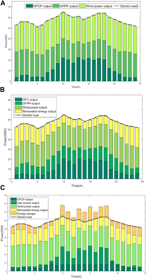
FIGURE 8. Output diagram of electric load unit. (A) Case 1. (B) Case 2. (C) Case 3.
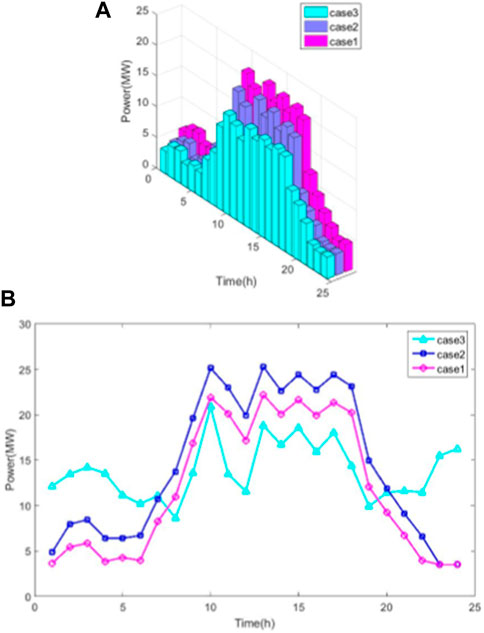
FIGURE 9. Output diagram of OFCP. (A) Excluding wind power accommodation. (B) Considering wind power accommodation.

FIGURE 10. Comparison of natural gas fuel consumption.
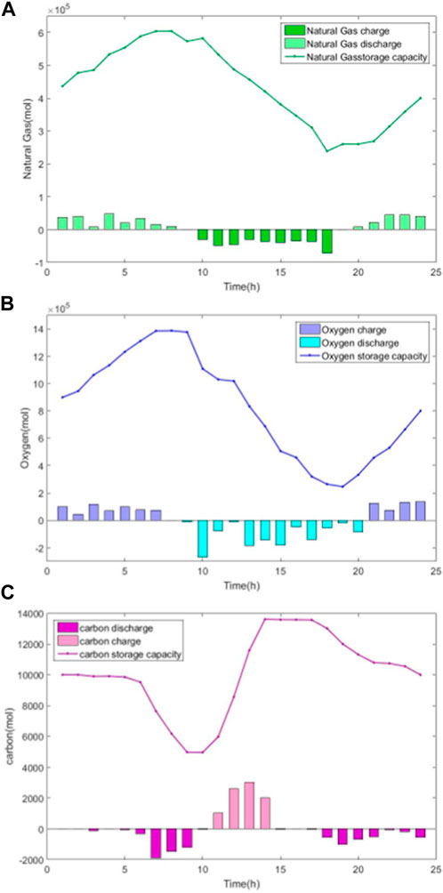
FIGURE 11. Variation curve of storage equipment. (A) Natural gas. (B) Oxygen. (C) Carbon dioxide.
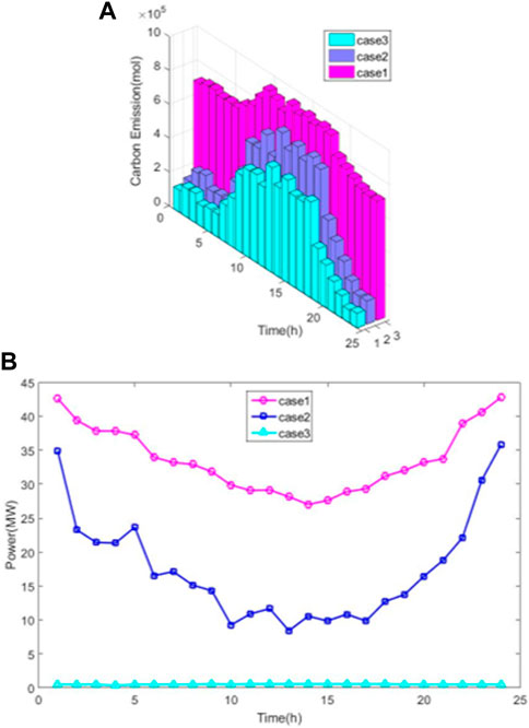
FIGURE 12. Comparison of Different Scenarios. (A) Dioxide emissions. (B) Curtailment rate.
Firstly, the OFCP-P2G-GFPPP composite system was proposed to analyze the relationship between energy flows within the system. Secondly, in the regional comprehensive energy system, establish an optimized scheduling model for the operation of the OFCP-P2G-GFPPP system. Finally, analyze the operating characteristics of two different modes. The characteristics and advantages of its basic model and capacity expansion model were discussed respectively, in order to improve the flexible operation mode of the comprehensive energy system.
(1) The OFCP-P2G-GFPPP combined system can effectively alleviate the power supply pressure of thermal power units. Reduce the use of purchased natural gas and increase the consumption of renewable energy. After adding energy storage equipment, it has the ability to “cut peak and fill valley”, which can achieve load transfer. OFCP-P2G-GFPPP has good low-carbon emission reduction capabilities and operational economic benefits.
(2) According to the example, it can be concluded that compared with the independent operation model, the basic model of the OFCP-P2G-GFPP system saves 9.14% of the total cost and reduces carbon emissions by 44.05%, which proves the importance of the OFCP-P2G-GFPP interconnected system in the low-carbon economic dispatch of the integrated energy system.
(3) According to the example, it can be concluded that compared with the independent operation model, the OFCP-P2G-GFPP system expansion model saves 13.05% of the total cost and reduces carbon emissions by 59.91%. Compared with the basic model, the OFCP-P2G-GFPP system expansion model saves 4.82% of the total cost and reduces carbon emissions by 28.34%. It proves the rationality of considering energy storage equipment and OFCP-P2G-GFPP interconnection system in the low-carbon economic dispatch of the integrated energy system.
The original contributions presented in the study are included in the article/supplementary material, further inquiries can be directed to the corresponding author.
RW: Supervision, Formal analysis, Writing–review and editing; XW: Writing-Original draft preparation; Formal analysis, Validation, Supervision, XW: Writing–review and editing, Validation; YF: Writing–review and editing, Validation; YZ: Supervision. All authors contributed to the article and approved the submitted version.
This work was supported by the Project of Jilin Province Education Department (JJKH20230118KJ).
YZ was employed by the State Grid Jibei Electric Power Company, Chengde Power Supply Company.
The remaining authors declare that the research was conducted in the absence of any commercial or financial relationships that could be construed as a potential conflict of interest.
All claims expressed in this article are solely those of the authors and do not necessarily represent those of their affiliated organizations, or those of the publisher, the editors and the reviewers. Any product that may be evaluated in this article, or claim that may be made by its manufacturer, is not guaranteed or endorsed by the publisher.
Chen, Q., Kang, C., and Xia, Q. (2010). Modeling flexible operation mechanism of CO2 capture power plant and its effects on power-system operation. IEEE Trans. Energy Convers.3 (25), 853–861. doi:10.1109/tec.2010.2051948
Cui, Y., Zeng, P., and Zhong, W. (2020). Low-carbon economic dispatch of electricity-gas-heat integated energy system considering oxy-fuel combustion technology. Proc. CSEE40 (18), 5827–5837. doi:10.13334/j.0258-8013.pcsee.191708
Dong, C., and Zhao, J. (2014). From smart grid to energy Internet: Basic concepts and research framework. Automation Electr. Power Syst.38 (15), 1–11. doi:10.7500/AEPS20140613007
Energy Resource Guide (2010). Germany invented "electricity to gas" method to solve the problem of renewable energy storage. Pet. Eng. Constr.3, 108–109.
Favre-Perrod, P. (2005). “A vision of future energy networks,” in 2005 IEEE power engineering society inaugural conference and exposition in Africa, Durban, South Africa, 11-15 July 2005 (IEEE), 13–17.
Geidl, M. (2007). Integrated modeling and optimization of multi-carrier energy system. Zurich: ETH, 16.
Ghorbani, B., Mehrpooya, M., and Ghasemzadeh, H. (2018). Investigation of a hybrid water desalination, oxy-fuel power generation and CO2 liquefaction process. Energy1 (158), 1105–1119. doi:10.1016/j.energy.2018.06.099
Gu, W., Wang, J., Lu, S., Luo, Z., and Wu, C. (2017). Optimal operation for integrated energy system considering thermal inertia of district heating network and buildings. Appl. Energy199, 234–246. doi:10.1016/j.apenergy.2017.05.004
Guandalini, G., Campanari, S., and Romano, M. C. (2015). Power-to-gas plants, and gas turbines for improved wind energy dispatch ability: Energy and economic assessment. Appl. Energy1 (147), 117–130. doi:10.1016/j.apenergy.2015.02.055
Hoekman, S. K., Broch, A., Robbins, C., and Purcell, R. (2010). CO2 recycling by reaction with renewably-generated hydrogen. Greenh. Gas. Control1 (4), 44–50. doi:10.1016/j.ijggc.2009.09.012
Hua, W., Jiang, J., and Suna, H. (2020). A blockchain based peer-to-peer trading framework integrating energy and carbon markets. Appl. Energy279, 115539. doi:10.1016/j.apenergy.2020.115539
Jiang, T. (2018). Optimal energy flow and nodal energy pricing in carbon emission-embedded integrated energy systems. CSEE J. Power Energy Syst.2 (4), 179–187. doi:10.17775/cseejpes.2018.00030
Karjunen, H., Tynjälä, T., and Hyppänen, T. (2017). A method for assessing infrastructure for CO2 utilization: A case study of Finland. Appl. Energy205, 33–43. doi:10.1016/j.apenergy.2017.07.111
Lu, P., Ye, L., and Tang, Y. (2019). Research on multi-time scale active power optimal dispatching strategy of wind power cluster based on model predictive control. Proc. CSEE39 (22), 6572–6583. doi:10.13334/j.0258-8013.pcsee.190188
Touretzky, C. R., McGuffin, D. L., Ziesmer, J. C., and Baldea, M. (2016). The effect of distributed electricity generation using natural gas on the electric and natural gas grids. Appl. Energy Sep.177, 500–514. doi:10.1016/j.apenergy.2016.05.098
UNCC (2016). Paris climate change agreement-climate change agreement. Paris: United Nation Climate Change.
Viebahn, P., Vallentin, D., and Höller, S. (2015). Prospects of carbon capture and storage (CCS) in China’s power sector – an integrated assessment. Appl. Energy157, 229–244. doi:10.1016/j.apenergy.2015.07.023
Viebahn, P., Vallentin, D., and Höller, S. (2014). Prospects of carbon capture and storage (CCS) in India’s power sector – An integrated assessment. Appl. Energy117, 62–75. doi:10.1016/j.apenergy.2013.11.054
Viklund, S. B., and Karlsson, M. (2015). Industrial excess heat use: Systems analysis and CO2 emissions reduction. Appl. Energy152, 189–197. doi:10.1016/j.apenergy.2014.12.023
Wang, W., Wang, D., and Jia, H. (2017). Steady-state analysis of electric power-natural gas regional integrated energy system considering the state of natural gas network. Proc. CSEE37 (5), 1293–1305. doi:10.13334/j.0258-8013.pcsee.160250
Wang, Y., Qiu, J., and Tao, Y. (2020). Low-carbon oriented optimal energy dispatch in coupled natural gas and electricity systems. Appl. Energy280, 115948. doi:10.1016/j.apenergy.2020.115948
Wang, Y., Wang, Y., Huang, Y., Yang, J., Ma, Y., Yu, H., et al. (2019). Operation optimization of regional integrated energy system based on the modeling of electricity-thermal-natural gas network. Appl. Energy251, 113410. doi:10.1016/j.apenergy.2019.113410
Wang, Z., Kuang, J. C., Pang, H. Q., and Huo, Z. L. (2014). Cost analysis of CO2 geological storage in deep saline formation. A Sci. A Technol. Rev.1 (31),46–53. doi:10.3981/j.issn.1000-7857.2014.006
Yang, J. (2019). Modeling the operation mechanism of combined P2G and gas-fired plant with CO2 recycling. IEEE Trans. Smart Grid1 (10), 1111–1121. doi:10.1109/tsg.2018.2849619
Zeng, Q., Fang, J., and Li, J. (2016). Steady-state analysis of the integrated natural gas and electric power system with bi-directional energy conversion. Appl. Energy184, 1483–1492. doi:10.1016/j.apenergy.2016.05.060
Zhang, X. (2015). Optimal expansion planning of energy hub with multiple energy infrastructures. IEEE Trans. Smart Grid5 (6), 2302–2311. doi:10.1109/tsg.2015.2390640
Keywords: oxy-fuel combustion, carbon-oxygen flow, power to gas, carbon emissions, regional integrated energy system
Citation: Wang R, Wen X, Wang X, Fu Y and Zhao Y (2023) Low-carbon economic dispatch of regional integrated energy system based on carbon-oxygen cycle. Front. Energy Res. 11:1206242. doi: 10.3389/fenrg.2023.1206242
Received: 15 April 2023; Accepted: 22 June 2023;
Published: 12 July 2023.
Edited by:
Siamak Hoseinzadeh, Sapienza University of Rome, ItalyReviewed by:
Hassan Bazazzadeh, Poznań University of Technology, PolandCopyright © 2023 Wang, Wen, Wang, Fu and Zhao. This is an open-access article distributed under the terms of the Creative Commons Attribution License (CC BY). The use, distribution or reproduction in other forums is permitted, provided the original author(s) and the copyright owner(s) are credited and that the original publication in this journal is cited, in accordance with accepted academic practice. No use, distribution or reproduction is permitted which does not comply with these terms.
*Correspondence: Xiuyun Wang, dy14aXUteUAxNjMuY29t
Disclaimer: All claims expressed in this article are solely those of the authors and do not necessarily represent those of their affiliated organizations, or those of the publisher, the editors and the reviewers. Any product that may be evaluated in this article or claim that may be made by its manufacturer is not guaranteed or endorsed by the publisher.
Research integrity at Frontiers
Learn more about the work of our research integrity team to safeguard the quality of each article we publish.