 Chang Yan1
 Nina Dai
95% of researchers rate our articles as excellent or good
Learn more about the work of our research integrity team to safeguard the quality of each article we publish.
Find out more
ORIGINAL RESEARCH article
Front. Energy Res. , 20 June 2023
Sec. Solar Energy
Volume 11 - 2023 | https://doi.org/10.3389/fenrg.2023.1205851
This article is part of the Research Topic Advanced Solar Utilization and Control Technologies in Buildings View all 5 articles
It is a challenging task to accurately track the global maximum power point (GMPP) in a changing environment in widely used photovoltaic (PV) systems. So far, a variety of maximum power point (MPP) tracking algorithms have been used in solar PV power systems. The classical algorithm is simple and fast to track the speed effectively in a constant environment, but it can get stuck at an extreme point in a variable environment. In this paper, the variable-step incremental conductance (VINC) method is combined with the gray wolf optimization (GWO) algorithm. Firstly, GWO conducts a global search. When the search reaches the area near GMPP, the next step of the search process is carried out based on the iteration number conditions of GWO. Enter the search process of VINC and determine whether the current search process is on the left or right side of the vertex based on the current search value. And adjust the duty cycle during the VINC search process using different variable step size methods based on the left and right sides, and finally accurately locate the GMPP value. To verify the robustness of the proposed algorithm, simulation, and experimental comparisons were conducted between the proposed method in the article and GWO and VINC. The tracking efficiency of static shadows, simulated dynamic shadows, and experimental static and dynamic shadows is 99.80%, 98.82%, 99.43%, and 98.51%, respectively. The tracking time of simulation and experiment is 46.49% and 89.34% faster than GWO and VINC technologies, respectively. The results show that compared with the GWO and VINC methods, the proposed method has improved tracking speed and efficiency. Moreover, compared with the method that combines the two intelligent algorithms, this method has fewer algorithm parameters, a simple calculation process, lower complexity, lower hardware requirements, and better actual implementation performance.
With the advancement of global energy development, different influencing factors between regions, the importance attached to the PV industry by various countries, and the market requirements of green energy, the global PV power generation industry continues to grow and will become the mainstay of new energy generation. However, the conversion efficiency of the modules used to collect solar energy is very low, limiting the collection of optimal solar energy (Ludin et al., 2021). With the continuous development of photovoltaic power generation technology and the increase in the rooftop photovoltaic industry, photovoltaic power generation faces strong variability in the external ambient temperature, light intensity, and other conditions, and the output voltage and current of the photovoltaic source show a non-linear trend (Chitransh et al., 2021). The output energy is related to the parameters of the photovoltaic panels, which, in turn, leads to the load imposing its characteristics on the output power; the P-U characteristic curve shows multiple peaks, and there is only one maximum value and multiple extremes in these peaks (Javed et al., 2019), with the power generation system unable to make sure the output power is at the maximum value at all times, leading to a serious reduction in the power generation efficiency of the PV panel; thus, the maximum power from the PV panel, especially under fluctuating weather conditions, while taking into account stability and output power maximization, is a research concern.
To solve this problem and increase the output power of PV panel power generation under any condition, a lot of research has been carried out on the MPPT control technique tracked by many scholars (Katche et al., 2023). Traditional techniques have been proposed, including the perturbation observation method (Martinez et al., 2022), incremental conductance method (Singh et al., 2021), fractional open-circuit voltage method (Hmidet et al., 2021), fractional short-circuit current method (Fapi et al., 2021), voltage scan (Celikel et al., 2022), and several methods of improvement (Khodair et al., 2023), among which the improved methods based on the incremental conductance method are the use of the incomplete partial differential theory partitioning variable step, integrator variable step (Harrison et al., 2023)—tracking about four times faster than INC—stepless voltage perturbation superposition adaptive improvement of the INC method (Chellakhi et al., 2022)—tracking efficiency than INC on average by about 2%—and the new adaptive step (Mishra et al., 2021); these algorithms have their advantages and disadvantages. The traditional techniques are used more in the current practical production because of their low hardware complexity and requirements, and easy operation; however, with the scale of photovoltaic power generation and the changing circumstances of the environment, the output power is relatively low and easy to fall into the extreme value point at the rapidly changing and partially shaded conditions that cannot get the real GMPP; the improved algorithm in the local shade can be tracked to the GMPP, but the use of logarithms, integration, and other methods to increase the complexity of the calculation, to a certain extent, will increase the power loss, ensuring that the completion of real-time tracking is also lacking. Among them, the incremental conductance method is more simple and accurate than other traditional techniques, with higher tracking accuracy and easier-to-achieve improvements in its step size. To improve the power generation efficiency, some bio-intelligence algorithms are proposed, including the particle swarm algorithm (Bai et al., 2021) with a 13.4% increase in output power, gray wolf optimization algorithm (Suhardi et al., 2019) with 0.4 s faster than INC, and fuzzy logic control (Giurgi et al., 2022) with 19% increase in conversion efficiency and 0.03 s faster tracking time than INC and artificial neural network (Dangi et al., 2022), and these methods have tracking accuracy and time that are much improved than traditional algorithms, but the complexity of the algorithm is increased, the search range is wider, the required search time is long, the amount of algorithm acquisition is increased, and the hardware requirements are higher. However, among several intelligent algorithms, the gray wolf optimization algorithm has fewer parameters, which is simpler to implement, and is widely used (Al-Tashi et al., 2020). In addition, for the current problem at the point of falling into extremes, fusion technology algorithms have been proposed, such as the genetic algorithm and fractional open-circuit voltage hybrid algorithm (Hassani et al., 2023); after a 3% increase in efficiency over the fractional open-circuit voltage method, improved artificial bee swarm and simultaneous heat-transfer search algorithm combination (Gong et al., 2023) achieved a tracking efficiency of more than 98%, the particle swarm algorithm combined with the optimized perturbation observation algorithm and incremental conductance method algorithm (Ibrahim et al., 2023) achieved a tracking efficiency of 99.07% and a tracking time of 43.4 m, the hybrid MPP tracking technique implemented by the incremental conductance method and the dragonfly optimization technique reduced the tracking time and improved the accuracy (Sarwar et al., 2022), and the two methods of the gray wolf optimization algorithm and the whale optimization algorithm for simultaneous PID control (Abderrahim et al., 2021) reduced the tracking time by 0.75 s and improved the efficiency by 1.2%. Adjusting the parameters to ensure the real-time tracking of the MPP in a rapidly changing environment, the aforementioned multiple fusion techniques better achieve the MPPT tracking effect, oscillations are reduced, tracking efficiency is improved, and tracking speed is accelerated despite the improvement in many aspects; however, the actual production requires to achieve low-cost and high-efficiency power generation, and the mixture of multiple intelligent algorithms is relatively complex and has high hardware requirements, high cost, and is more difficult to implement. To reduce the search range and complexity, as well as to shorten the search time and improve the tracking accuracy, this paper proposes to apply the algorithm of GWO combined with improved INC to the PV power generation system, where the GWO algorithm completes the global search to determine the approximate range of GMPP, and then, the variable-step INC completes the final precise positioning to quickly and accurately track the GMPP in the variable environment.
Because there are many kinds of photovoltaic cells and the mathematical model is very complex, it can be regarded as a stable output current source according to the working principle of photovoltaic cells. An engineering mathematical model is built based on the MPP voltage
where
The experimental part needs to realize the change in external conditions such as light and temperature under the PV system and complete the comparison simulation experiment under various conditions. The PV array model is a series of five panels. The characteristics of PV panels under partial shadow can be described as follows: a single PV cell can produce a few watts of electricity, and multiple PV cells are connected in series to form a PV string, which is then connected in parallel to form a PV panel. One of the partial shading conditions (PSCs) is a phenomenon that occurs when some parts of a PV panel receive a different intensity of light radiation irradiation compared to other parts. In a series-connected PV panel, the part exposed to weak light radiation intensity (shading condition) generates low current, while the current in the series-connected module remains the same; at this time, the part in the shading condition will operate under reverse bias conditions, which will make the voltage at both ends of the series-connected module decrease significantly; at this time, a hot spot will be generated, and this phenomenon will also cause damage to the PV module. In order to reduce the partial shading and reduce the large power loss caused by the partial shadowing condition, bypass diodes are used to minimize the impact of this phenomenon. The PV string under STC and PSC is shown in Figure 1. Under STC, all cells are used as current sources, and all diodes operate in reverse bias; when the PV panel is operated under a PSC environment, the cells under shaded conditions are equivalent to an open circuit and the bypass diodes operate in forward bias. Therefore, when the temperature is constant, the P-V characteristic curve obtained by gradually reducing the temperature to 400 W/m2 when the light radiant intensity is irradiated is shown in Figure 2A; when the light radiant intensity is constant and the temperature changes, the P-V characteristic curve is obtained, as shown in Figure 2B.
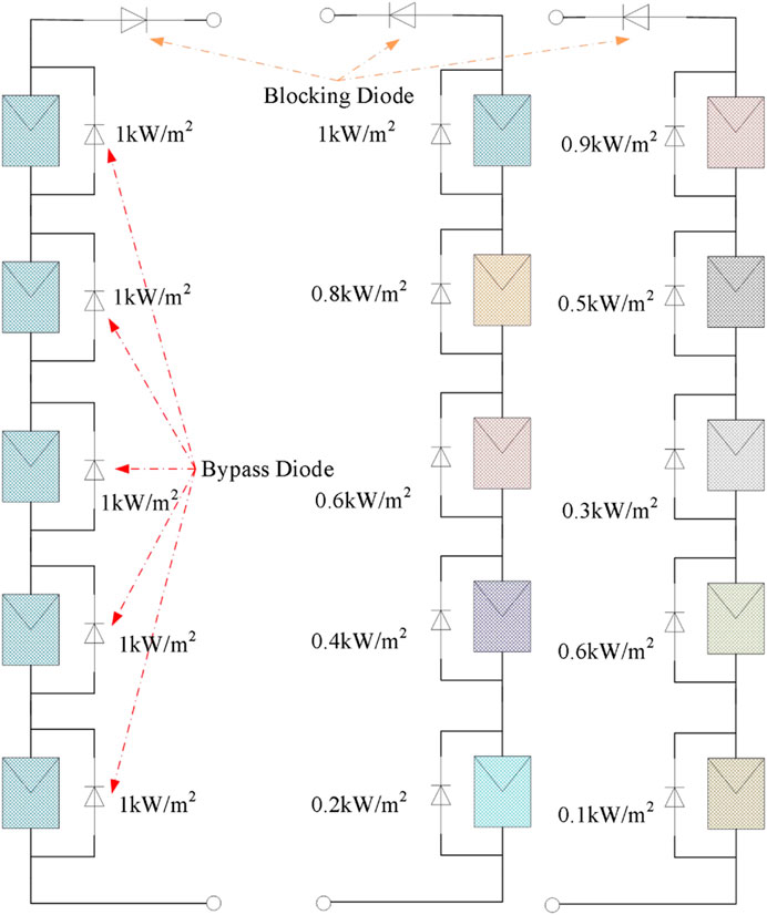
FIGURE 1. Photovoltaic string under STC and PSC.
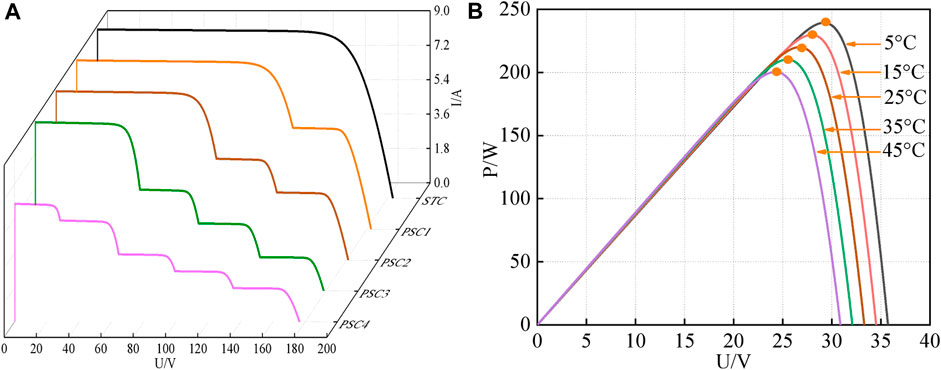
FIGURE 2. Characteristic curve of a photovoltaic panel (A) P-V curves of PV system under STC and 4 different light intensities (B) P-V curves of PV system at STC and 4 different temperatures.
The two P-V characteristic curves show that when the light radiant intensity changes, the power changes with the change, and there are multiple extreme points. Among these extreme points, only one point is the largest, which is GMPP. With the change in the temperature, the MPP value also changes, and the light radiant intensity has a greater impact on GMPP. Therefore, the P-V characteristic curve will show multi-peak under the shadow condition. To maximize the output power, the circuit must work at GMPP.
In this paper, the photovoltaic system structure shown in Figure 3 is adopted to demonstrate the performance of the GWO-VINC method, which mainly consists of a PV panel, boost circuit, MPPT controller, PI controller, and PWM driver circuit. In the boost circuit, C is the input filter capacitor, L is the energy storage inductor, V is the switching tube, VD is the diode, C0 is the output filter capacitor, and R is the load.
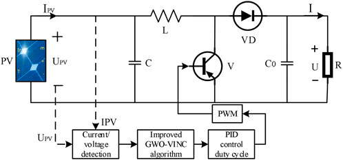
FIGURE 3. MPPT control schematic diagram based on the boost converter.
To design the closed-loop voltage control, the PV system needs to be modeled. In MATLAB/Simulink, the simulation model of Figure 4 was built according to the circuit schematic diagram of Figure 3, in which the output voltage of the PV cell was taken as the standard value of PID control.
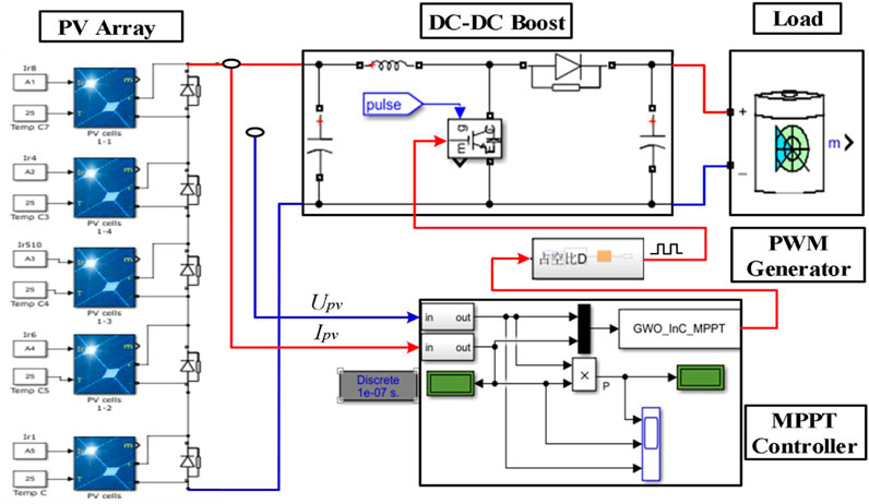
FIGURE 4. GWO-VINC algorithm simulation model.
The PV module of PV array 1 is shown in Figure 4. The PV module of TP250MBZ using Simulink software is selected as the research object. The basic parameters of the standard external environment provided by the manufacturer of the PV module are shown in Table 1. The parameters of the boost circuit were calculated according to the output voltage of the simulation circuit, and the frequency of the inductor, capacitor, load, and switch is calculated, as shown in Figure 3 and in Table 1.
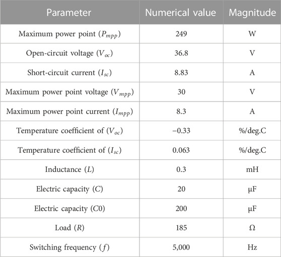
TABLE 1. Circuit parameter setting.
The characteristics of the PV battery pack are observed in 2.2, the PV string is connected to the built simulation circuit, and the light conditions of the string are changed to check the obtained characteristic curves to verify whether the simulation model is built correctly, which can be used for the simulation experiment of MPPT control technology with the improved algorithm at the later stage. The simulation under the conditions of Table 2 yields the curve graph shown in Figure 5.
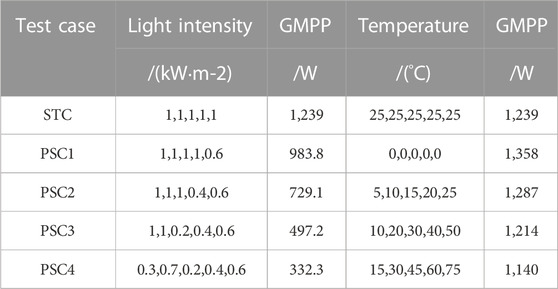
TABLE 2. Five different test conditions.
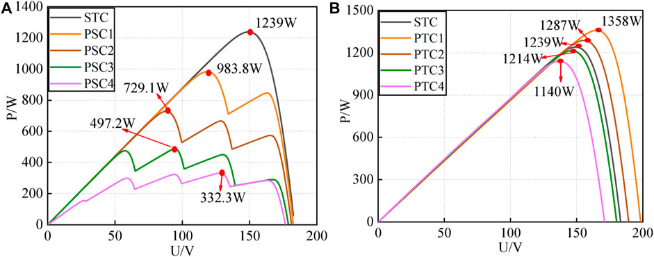
FIGURE 5. Characteristic curve of a photovoltaic panel (A) P-V curves of PV system under STC and 4 different light intensities (B) P-V curves of PV system at STC and 4 different temperatures.
Figure 5 shows that the output power is consistent with the theoretical light radiation intensity change and temperature change on the output power, and the output GMPP is consistent with the output power value under known conditions; thus, the simulation model can be used to conduct simulation experiments under different conditions.
The GWO algorithm is an optimization search method inspired by the management system of gray wolf hunting activities developed by the four layers
Equation 3 represents the distance between the individual and the prey, and is the current position of the gray wolf; Eq. 4 is the position updated formula of the gray wolf.
where
In Eq. 7,
Equation 8 defines the width and direction in which the
The schematic diagram of GWO position update is shown in the following Figure 6.
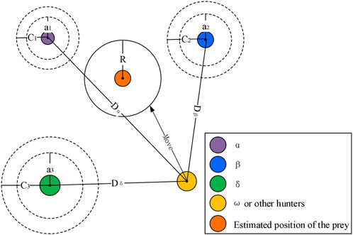
FIGURE 6. Schematic diagram of the GWO position update.
The traditional INC has a simple operation, which is easy to implement and is widely used in photovoltaic power generation systems, but many of the methods proposed to improve INC are more complicated, and there are currently disturbances and observation methods that improve the variable-step size into three different regions, before and after reaching MPP, and improve the step size in different ways (Liu et al., 2014). Gupta et al. (2021) proposed that P&O use different methods to improve the step size on both sides of the MPP, and then track (Gupta et al., 2021) and divide INC into two regions to change different step sizes for improvement. The methods proposed in the above references have achieved good tracking results. Furthermore, the principle of the INC method is to determine the change in the disturbance step size by
As can be seen in Figure 7, the traditional INC has a different magnitude of voltage change before and after the MPP non-linear region, with a large variation range on the left side and a small variation range on the right side. In the paper, the traditional INC method is separated based on the P-V curve apex, and different tracking step coefficients are set as
where
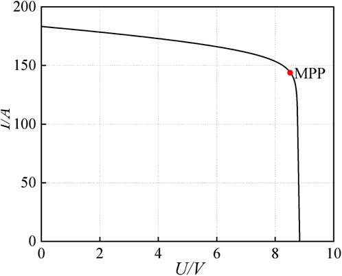
FIGURE 7. I–V characteristic curve of photovoltaic cells under STC.
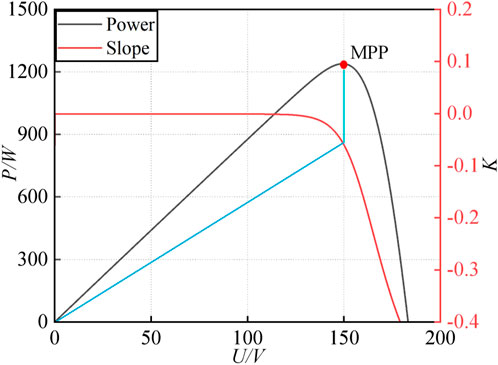
FIGURE 8. Slope and the P-V curve of the photovoltaic cell curve under STC.
The specific implementation flow chart is shown in Figure 9.
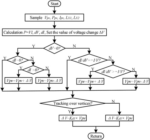
FIGURE 9. Flow chart of VINC.
In the PV power generation system, the MPPT strategy controls the duty cycle of the commutator in the boost circuit. Among them, the individual gray wolf is the duty ratio of GWO, and the global optimal value is the target prey. When the external environment changes, the MPPT control technology based on the GWO-VINC algorithm first starts GWO to complete the initialization of voltage/current and other parameters, power calculation, and comparison of global search; after several iterations, with the continuous updating of the location of individual gray wolves, when the location of the gray wolf population tends to be the same, the difference of the output power is decreasing, and the search approaches near the global maximum. As the value of GWO algorithm iterations increases, it reaches the maximum number of iterations, stops iterating, jumps out of the cycle, and enters the next level of the search process, and the VINC algorithm precisely searches and locates the maximum point to improve the accuracy of tracking, enhance the stability of the output voltage of the whole system, and increase the output power efficiency of the PV system. When external environmental factors cause the light intensity, temperature, and other conditions to change, the output power characteristics of the PV array also change. The duty cycle maintained at this time may no longer correspond to the MPP, and the algorithm needs to be restarted to search for a new MPP. When the system detects that the current power
The specific implementation flow chart is shown in Figure 10.
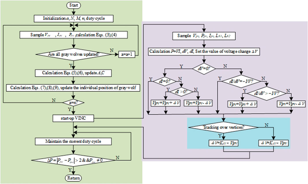
FIGURE 10. Flow chart of GWO-VINC.
To compare the tracking effect of GWO-VINC with GWO and VINC methods, to simulate the external environment change of PV power generation, and to verify that the proposed method can respond quickly to track GMPP under a variable environment, three modes are set as follows: the ideal no-shade state (as a reference), static shade state (the external environment changes slightly and is stable after one change), and dynamic shade state (the external environment changes strongly, and the temperature and light change at any time); the simulation and experimental verification are carried out in this mode.
To verify the effectiveness of the proposed method, GWO-VINC, GWO, and VINC methods were compared with it and simulated in both static and dynamic shading modes to track time and static tracking efficiency
where
The P-V curve of the PV system under STC is single-peaked. At this time, the light level received by the PV panel is all standard irradiance (1000 W/m2), the working temperature is all standard temperature (25°C), and the maximum power of the PV system is PSTC = 1239 W. In this case, the output power and voltage curves of the three algorithms are shown in Figures 11, 12.
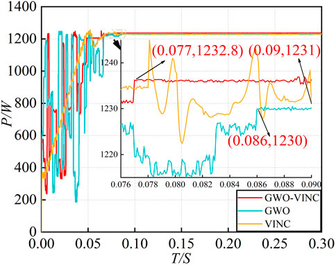
FIGURE 11. Tracking P-T curve under static non-shade conditions.
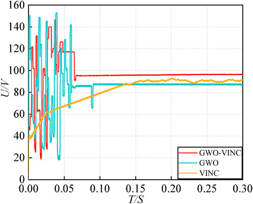
FIGURE 12. Tracking V-T curve under static non-shade conditions.
As can be seen from Figure 11, the tracking effect based on the GWO-VINC algorithm is more stable than both GWO and VINC methods, the GWO-VINC algorithm has a stable tracking power near 1232.8 W at 0.077 S with an accurate tracking efficiency of 99.50%, the GWO algorithm has a stable tracking power near 1230 W at 0.086 S with an accurate tracking efficiency of 99.27%, and the VINC algorithm tracked the power around 1231 W at 0.090 S with 99.35% accurate tracking efficiency.
According to the aforementioned analysis and simulation waveform, it can be seen that in this case, the tracking efficiency of all three methods is above 99%, and the GWO-VINC algorithm tracks faster and with higher accuracy; this is mainly because of the addition of GWO that accelerates the tracking speed, and the tracking accuracy of VINC is improved when it enters the vicinity of the MPP. It can also be seen from Figure 12 of the tracking voltage variation with the time that the GWO-VINC algorithm has a smaller voltage variation.
In the case of static PSC, the P-V curve of the PV module shows multiple peaks. The light irradiance received by the PV panel is set to 500, 400, 900, 800, and 1000 W/m2, and the operating temperature is set to 25, 5, 15, 30, and 35°C, respectively. The output power and voltage curves of the three algorithms are shown in Figures 13, 14.
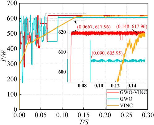
FIGURE 13. Tracking P-T curve under static shading conditions.
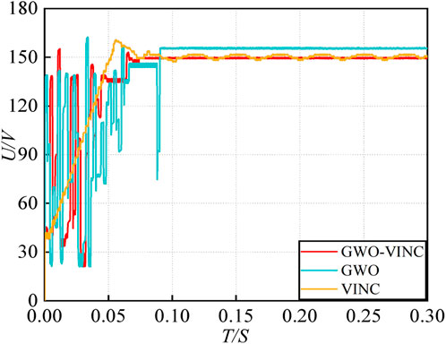
FIGURE 14. Tracking V-T curve under static shading conditions.
Figure 13 shows that the GWO-VINC algorithm has a stable tracking power near 617.96 W at 0.0667 S with an accurate tracking efficiency of 99.75%, the GWO algorithm has a stable tracking power near 605.95 W at 0.090 S with an accurate tracking efficiency of 97.93%, and the VINC method has a stable tracking power near 617.96 W at 0.148 S with an accurate tracking efficiency of 99.75%. Figures 13, 14 show that all the three methods respond rapidly at the instant of starting tracking, where the GWO-VINC algorithm reduces the tracking time by 124.2% compared with VINC and improves the tracking accuracy by 1.99% compared with GWO; the tracking accuracy of GWO-VINC and VINC is not much different, indicating that the tracking accuracy can be improved by adding VINC under shade conditions and produces smaller voltage oscillation amplitude, reduces the power loss, and improves the conversion efficiency of PV cells.
In the actual working environment, the local shadow may change with time, and the environment around the PV module, including light intensity, temperature, and shadow, may be different from the previous time, so this multi-peaked P-V curve is time-varying. In Simulink, the dynamic tracking effect of the PV module in three different environments, as shown in Table 3, is simulated; the PSC1–PSC2 switching time point is 0.2 s, and the PSC2–PSC3 switching time point is 0.4 s.

TABLE 3. Three working environment parameters.
The simulated waveforms of power tracking under dynamic PSC of the three methods are shown in Figures 15, 16. Under PSC1, the three methods took 0.092, 0.096, and 0.153 S to complete power tracking, and the final output values were 707.37, 705.88, and 706.87 W, with tracking efficiencies of 99.70, 99.49, and 99.63%, respectively. Under PSC2, the three methods took 0.103, 0.121, and 0.176 S to complete the power tracking, and the final output values were 474.35, 466.99, and 473.01 W, respectively, with tracking efficiencies of 99.32%, 97.78%, and 99.04% respectively. The final output values were 331.53, 326.7, and 326 W respectively, with tracking efficiencies of 99.26%, 95.81%, and 98.80% respectively. According to the aforementioned data, the tracking accuracy of GWO-VINC is above 99%, which is improved compared with the GWO method. The addition of the VINC method improves the tracking accuracy, and the tracking speed of GWO-VINC is increased by 67.96% at the maximum, which is better than that of GWO and VINC; the speed is faster than that of VINC because the access of GWO speeds up the tracking speed, the vibration is small, and the response speed is fast in the search process.
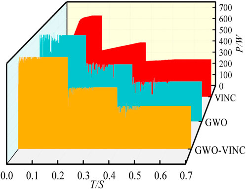
FIGURE 15. Tracking P-T curve under the dynamic shadow.
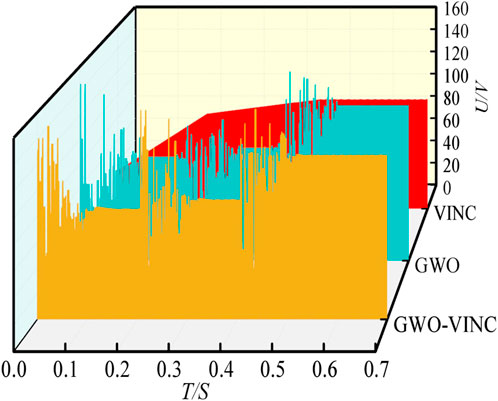
FIGURE 16. Tracking V-T curve under the dynamic shadow.
The verification is carried out on the hardware experiment platform based on Yanxu TMS320F28335 control. As shown in Figure 17, the experimental equipment mainly includes a PV analog source, MPPT controller, 50 Ω adjustable power resistor, digital multimeter, and digital oscilloscope. Among them, the PV analog source simulates the PV panel; the 50 Ω adjustable power resistor simulates the load.
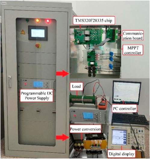
FIGURE 17. Experimental platform.
Figure 18 shows that the GWO-VINC method tracking time is 20.33% and 47.46%, which is less than the GWO and VINC tracking time, respectively, and the tracking accuracy of the three methods in this state is not much different, and they are all stable around 612 W. Figure 19 shows that the tracking voltage fluctuation of the GWO-VINC method is small, and the fluctuation enters a steady state soon with better stability.
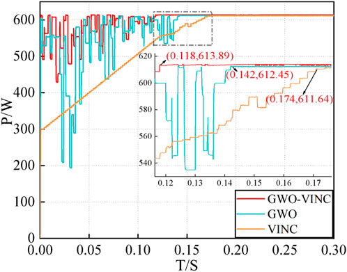
FIGURE 18. Tracking P-T curve under the static shadow.
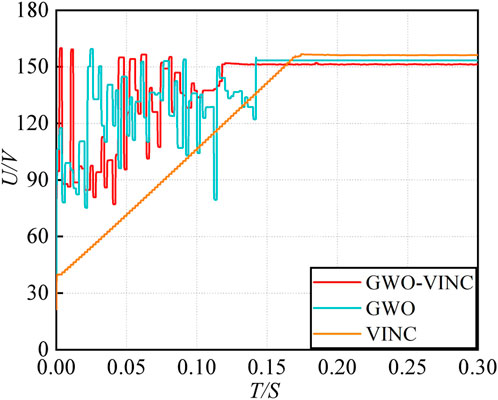
FIGURE 19. Tracking V-T curve under the static shadow.
The aforementioned figure shows that the PSC1–PSC2 switching time point is 0.2 s, the PSC2–PSC3 switching time point is 0.4 s, and the power tracking simulation waveforms under dynamic PSC of the three methods are shown in Figures 20, 21. Under PSC1, the three methods took 0.097, 0.131, and 0.160 S to complete the power tracking, and the final output values were 696.37, 694.74, and 678.85 W, with tracking efficiencies of 98.15%, 97.92%, and 95.68%, respectively. Under PSC1–PSC2, the three methods took 0.121, 0.154, and 0.035 S to complete the power tracking, and the final output values were 471.96, 462.03, and 456.97 W, with tracking efficiencies of 98.82%, 96.74%, and 95.68%, respectively. In this state, the tracking time of VINC is relatively short. The reason may be that VINC tracking has fallen into local optima. Because GMPP under PSC2 is the first extreme point on the P-V characteristic curve. When the external environment changes, the VINC method will restart tracking and stop tracking after completing the first point tracking, ending the entire tracking process. Therefore, in this state, VINC has the shortest tracking time. Under PSC2–PSC3, the three methods took 0.132, 0.163, and 0.036 S to complete the power track, where the final output values were 329.19, 326.78, and 320.78 W, and tracking efficiencies were 98.56%, 97.84%, and 96.04%; at this time, VINC time is the shortest, specifically because the voltage is increasing, and the change is small, although it can track the MPP in a short time; the voltage increase increases the loss of the circuit, and the actual long-term use of the production is not recommended to change the method. By combining the P-T and V-T diagrams and data, it can be seen that the overall tracking effect of GWO-VINC is the best, the tracking accuracy is guaranteed to be above 99%, and the oscillation amplitude is minimal.
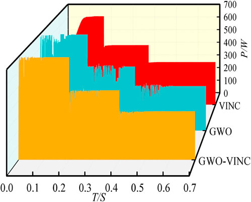
FIGURE 20. Tracking P-T curve under the dynamic shadow.
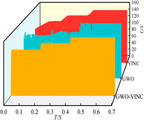
FIGURE 21. Tracking V-T curve under the dynamic shadow.
Based on the analysis of the aforementioned three sets of the experimental data, based on GWO, the tracking accuracy is improved due to the addition of VINC; based on VINC, the tracking speed is faster to some extent due to the addition of GWO.
The data under dynamic shading simulation and the experiment were calculated and summarized, as shown in Table 4.

TABLE 4. Correspondence table of simulation and experimental results.
According to Table 4, the tracking effect of the GWO-VINC method is the best among the three methods, with an average reduction of 50.01% in tracking time and an average improvement of 1.90% in tracking accuracy relative to GWO and VINC. Under a dynamic environment, the GWO-VINC method reacts quickly, has the highest tracking accuracy, and the least fluctuation, which is beneficial to reduce the power loss of the system, and it can be seen from the comparison of simulation and experimental conditions that although the superiority of GWO-VINC method is achieved by increasing the complexity of both GWO and VINC methods, the tracking accuracy and tracking time of GWO-VINC method are improved, which is more adaptable to the case of large changes in external conditions and matches the changing conditions of PV power generation systems in real life.
In this section, three different cases are studied after reading the literature and comparing the results of several simulation experiments, and the performance and tracking effect of the proposed algorithm are comprehensively expounded. The photovoltaic system simulation model with MPPT control technology was built using MATLAB/Simulink, and the tracking effect of three different MPPT control technologies in three cases was determined by writing C language code experiment, case 2 static shading, and case 3 dynamic shading. The tracking effect and advantages of the GWO-VINC method can be better than two cases. First, it can be clearly seen from the curves of P-T and V-T that the oscillation amplitude of GWO-VINC is smaller than that of GWO and VINC, and the tracking stability performance of GWO-VINC is better. Even under the dynamic and changeable condition, the curve of the GWO-VINC method is relatively smooth, indicating that the stability performance of the proposed method is better than that of the other two methods. Thus, the power loss caused by the oscillation of the circuit is less, which helps improve the power output efficiency of photovoltaic power generation. Second, from the tracking time data collected and calculated in Table 4, it can be seen that the tracking time of the proposed methods is the shortest when the VINC method does not fall into the local optimal case. This is mainly because when GWO is used to quickly locate near the maximum power point, the algorithm quickly enters VINC for accurate positioning. In order to reduce the time consumption of the more complex algorithm GWO in the final precise positioning stage, the tracking time is shortened. The simulation and experimental tracking time results are 46.49% and 89.34%, which are faster than GWO and VINC methods, respectively. Finally, it can also be seen from the tracking time data collected and calculated in Table 4 that GWO has the highest tracking efficiency, especially because the GWO can accurately locate the range of the GMPP. On this basis, VINC has a better ability to accurately track within the specified range. Therefore, the method combined with the two algorithms achieves better tracking effects and higher tracking accuracy, and the tracking efficiency of static shading and dynamic shading under simulation, and static shading and dynamic shading under experiment reaches 99.80%, 98.82%, 99.43%, and 98.51% respectively. Although the tracking stability, time, and efficiency of GWO-VINC are improved compared with those of GWO and VINC, the complexity of the GWO-VINC algorithm is higher than that of these two methods, and the requirements on hardware are also higher than those of these two methods. However, under the condition of considering the power generation cost and power generation efficiency factors, the tracking efficiency of GWO-VINC is 2.14%, which is higher than that of VINC, and GWO-VINC is 1.63%, which is higher than that of GWO.
Aiming at the problem that it is difficult for a photovoltaic power generation system to track GMPP in real time under the condition of the changeable external environment and local shadow, a photovoltaic power generation MPPT control strategy based on the integration of GWO and progressive VINC was proposed. In order to avoid falling into local optimization, GWO tracking is used at first. When it reaches the vicinity of GMPP, VINC tracking is started according to the conditions for starting VINC tracking. The two methods are combined to improve tracking accuracy and global search ability. By comparing with GWO and VINC methods using MATLAB simulation and hardware equipment experiments, it is verified that the GWO-VINC method has a faster tracking speed, and the power tracking accuracy can reach 99% under static, static shading, and dynamic shading conditions. The tracking time is the shortest among the three methods and can quickly adapt to changes in the external environment. Moreover, according to the V-T diagram, it can be seen that the overall stability of the GWO-VINC method is better, and the voltage fluctuation is smaller.
The original contributions presented in the study are included in the article/Supplementary Material; further inquiries can be directed to the corresponding author.
All authors listed have made a substantial, direct, and intellectual contribution to the work and approved it for publication.
This work was supported by the Natural Science Foundation Project of Chongqing Science and Technology Commission (grant numbers cstc2021jcyj-msxmX0301, cstc2020jcyj-msxmX0034, CSTB2022NSCQ-MSX1320, and 2022NSCQ-MSX4086), the Science and Technology Research Program of Chongqing Municipal Education Commission (grant numbers KJZD-K202101202 and KJZD-K202103401), the Chongqing Wanzhou District Science and Technology plan project (grant number: wzstc20220301), the Chongqing Three Gorges University graduate research and innovation project (grant number: YJSKY23044), and the Science and Technology Research Program of Chongqing Municipal Education Commission (grant number: KJZD-K202201203).
Author ZJ was employed by the company Chongqing Three Gorges Hydropower Co., Ltd.
The remaining authors declare that the research was conducted in the absence of any commercial or financial relationships that could be construed as a potential conflict of interest.
All claims expressed in this article are solely those of the authors and do not necessarily represent those of their affiliated organizations, or those of the publisher, the editors, and the reviewers. Any product that may be evaluated in this article, or claim that may be made by its manufacturer, is not guaranteed or endorsed by the publisher.
Abderrahim, Z. (2021). A new improved variable step size MPPT method for photovoltaic systems using grey wolf and whale optimization technique based PID controller. doi:10.18280/jesa.540120
Al-Tashi, Q., Md Rais, H., Abdulkadir, S. J., Mirjalili, S., and Alhussian, H. (2020). A review of grey wolf optimizer-based feature selection methods for classification. Evol. Mach. Learn. Tech. Algorithms Appl., 273–286. doi:10.1007/978-981-32-9990-0_13
Bai, J., Sun, L., Pachauri, R. K., and Wang, G. (2021). Investigation on photovoltaic array modeling and the MPPT control method under partial shading conditions. Int. J. Photoenergy 2021, 1–16. doi:10.1155/2021/8813717
Celikel, R., Yilmaz, M., and Gundogdu, A. (2022). A voltage scanning-based MPPT method for PV power systems under complex partial shading conditions. Renew. Energy 184, 361–373. doi:10.1016/j.renene.2021.11.098
Chellakhi, A., Beid, S. El, Abouelmahjoub, Y., and Mchaouar, Y. (2022). Optimization of power extracting from photovoltaic systems based on a novel adaptable step INC MPPT approach. IFAC Pap. 55 (12).
Chitransh, A., and Kumar, S. (2021). The different type of MPPT techniques for photovoltaic system. Indian J. Eng. Mater. Sci. 1 (4).
Dangi, P., Gawre, S. K., and Ojha, A. (2022). “Dynamic performance analysis of neural network based MPPT under varying climatic condition//Control,” in Applications in modern power systems: Select proceedings of EPREC 2021 (Singapore: Springer Nature Singapore), 163–176. doi:10.1007/978-981-19-0193-5_14
Doaa, Khodair, Saad, Motahhir, Mostafa Hazem, H., Ahmed, Shaker, Munim Hossam Abd El, , Mohamed, Abouelatta, et al. (2023). Modeling and simulation of modified MPPT techniques under varying operating climatic conditions. Energies 16 (1). doi:10.3390/EN16010549
Fapi, C. B. N., Wira, P., and Kamta, M. (2021). Real-time experimental assessment of a new MPPT algorithm based on the direct detection of the short-circuit current for a PV system. Parameters 145, 24. doi:10.24084/repqj19.358
Giurgi, G. I., Szolga, L. A., and Giurgi, D. V. (2022). Benefits of fuzzy logic on MPPT and PI controllers in the chain of photovoltaic control systems. Appl. Sci. 12 (5), 2318.
Gong, L., Hou, G., and Huang, C. (2023). A two-stage MPPT controller for PV system based on the improved artificial bee colony and simultaneous heat transfer search algorithm. ISA Trans. 132, 428–443. doi:10.1016/j.isatra.2022.06.005
Gupta, A. K., Pachauri, R. K., Maity, T., Chauhan, Y. K., Mahela, O. P., Khan, B., et al. (2021). Effect of various incremental conductance MPPT methods on the charging of battery load feed by solar panel. IEEE Access 9, 90977–90988. doi:10.1109/ACCESS.2021.3091502
Harrison, A., and Alombah, N. H. A new hybrid MPPT based on incremental conductance-integral backstepping controller applied to a PV system under fast-changing operating conditions. Int J Photoenergy, 2023. doi:10.1155/2023/9931481
Hassan, Aakash, Octavian, Bass, and Masoum Mohammad, A. S. (2023). An improved genetic algorithm based fractional open circuit voltage MPPT for solar PV systems. Energy Rep. 9. doi:10.1016/J.EGYR.2022.12.088
Hmidet, A., Subramaniam, U., Elavarasan, R. M., Raju, K., Diaz, M., Das, N., et al. (2021). Design of efficient off-grid solar photovoltaic water pumping system based on improved fractional open circuit voltage MPPT technique. Int. J. Photoenergy 2021, 1–18. doi:10.1155/2021/4925433
Ibrahim, M. H., Ang, S. P., Dani, M. N., Rahman, M. I., Petra, R., and Sulthan, S. M. (2023). Optimizing step-size of perturb & observe and incremental conductance MPPT techniques using PSO for grid-tied PV system. IEEE Access 11, 13079–13090. doi:10.1109/ACCESS.2023.3242979
Javed, M. Y., Mirza, A. F., Hasan, A., Rizvi, S. T. H., Ling, Q., Gulzar, M. M., et al. (2019). A comprehensive review on a PV based system to harvest maximum power. Electronics 8, 1480. doi:10.3390/electronics8121480
Katche, M. L., Makokha, A. B., Zachary, S. O., and Adaramola, M. S. (2023). A comprehensive review of maximum power point tracking (MPPT) techniques used in solar PV systems. Energies 16 (5), 2206. doi:10.3390/en16052206
Liu, Y. H., Chen, J. H., and Huang, J. W. (2014). Global maximum power point tracking algorithm for PV systems operating under partially shaded conditions using the segmentation search method. Sol. Energy 103, 350–363. doi:10.1016/j.solener.2014.02.031
Ludin, N. A., Affandi, N. A. A., Purvis-Roberts, K., Ahmad, A., Ibrahim, M. A., Sopian, K., et al. (2021). Environmental impact and levelised cost of energy analysis of solar photovoltaic systems in selected asia pacific region: A cradle-to-grave approach. Sustainability 13, 396. doi:10.3390/su13010396
Martinez Lopez, V. A., Žindžiūtė, U., Ziar, H., Zeman, M., and Isabella, O. (2022). Study on the effect of irradiance variability on the efficiency of the perturb-and-observe maximum power point tracking algorithm. Energies 15, 7562. doi:10.3390/en15207562
Mishra, J., Das, S., Kumar, D., and Pattnaik, M. (2021). A novel auto-tuned adaptive frequency and adaptive step-size incremental conductance MPPT algorithm for photovoltaic system. Int. Trans. Electr. Energy Syst. 31 (10), e12813. doi:10.1002/2050-7038.12813
Mokeddem, D. (2021). Parameter extraction of solar photovoltaic models using enhanced Levy flight based grasshopper optimization algorithm. J. Electr. Eng. Technol. 16 (1), 171–179. doi:10.1007/S42835-020-00589-1
Sarwar, S., Javed, M. Y., Jaffery, M. H., Arshad, J., Ur Rehman, A., Shafiq, M., et al. (2022). A novel hybrid MPPT technique to maximize power harvesting from pv system under partial and complex partial shading. Appl. Sci. 12 (2), 587. doi:10.3390/app12020587
Shinong, W., Qianlong, M., Jie, X., Yuan, G., and Shilin, L. (2020). An improved mathematical model of photovoltaic cells based on datasheet information. Sol. Energy 199, 437–446. doi:10.1016/j.solener.2020.02.046
Singh, P., Shukla, N., and Gaur, P. (2021). Modified variable step incremental-conductance MPPT technique for photovoltaic system. Int. J. Inf. Tecnol. 13, 2483–2490. doi:10.1007/s41870-020-00450-8
Suhardi, D., Syafaah, L., Irfan, M., Yusuf, M., Effendy, M., and Pakaya, I. (2019). “Improvement of maximum power point tracking (MPPT) efficiency using grey wolf optimization (GWO) algorithm in photovoltaic (PV) system,” in IOP conference series: Materials science and engineering, proceedings of the 2nd international conference on engineering and applied technology, aceh, Indonesia (Bristol, UK: IOP Publishing), 1–11. doi:10.1088/1757-899X/674/1/012038
Keywords: maximum power point tracking, variable environment, gray wolf optimization, variable-step incremental conductance, tracking efficiency
Citation: Yan C, Lei G, Cai L, He C, Dai N, Jiang Z, Wu J and Li S (2023) MPPT control technology based on the GWO-VINC algorithm. Front. Energy Res. 11:1205851. doi: 10.3389/fenrg.2023.1205851
Received: 14 April 2023; Accepted: 30 May 2023;
Published: 20 June 2023.
Edited by:
Tao Zhang, Shanghai University of Electric Power, ChinaReviewed by:
Chenglong Luo, Nanjing University of Science and Technology, ChinaCopyright © 2023 Yan, Lei, Cai, He, Dai, Jiang, Wu and Li. This is an open-access article distributed under the terms of the Creative Commons Attribution License (CC BY). The use, distribution or reproduction in other forums is permitted, provided the original author(s) and the copyright owner(s) are credited and that the original publication in this journal is cited, in accordance with accepted academic practice. No use, distribution or reproduction is permitted which does not comply with these terms.
*Correspondence: Nina Dai, RDE4NTk4NDcwODc0QG91dGxvb2suY29t
Disclaimer: All claims expressed in this article are solely those of the authors and do not necessarily represent those of their affiliated organizations, or those of the publisher, the editors and the reviewers. Any product that may be evaluated in this article or claim that may be made by its manufacturer is not guaranteed or endorsed by the publisher.
Research integrity at Frontiers
Learn more about the work of our research integrity team to safeguard the quality of each article we publish.