 Xiong Zheng
 Xianghui Lu*
- China Nuclear Power Technology Research Institute Co., Ltd., Shenzhen, China
Helical tubes are widely used in nuclear plants, heat recovery process, and refrigeration technology. The fluid is influenced by centrifugal force flow through the helical tube, accompanied by secondary flow which is conducive to the enhancement of heat transfer. However, the uneven circumferential heat transfer caused by the secondary flow was seldom reported, while the pressure drops and heat transfer characteristics of helical tubes under single-phase and two-phase flow conditions need to be supplemented. This paper investigated the friction pressure drop and circumferential heat transfer characteristics based on the experiments on helical tubes with the coil diameter to the tube diameter varying from 28.5 to 128.5 and lift angle varying from 3° to 10°. The results showed that the coil diameter was the key parameter affecting the pressure drop and non-uniform circumferential heat transfer, compared with the lift angle. At the same cross section, the heat transfer coefficient at the outside tube wall was the highest, which was more obvious under small coil diameter conditions. Correlations of flow resistance and heat transfer were proposed for the single-phase and saturated boiling two-phase flow, respectively, and the predicted values were improved compared with the prediction results of correlations in the existing literature.
1 Introduction
Helical tubes have been widely used in nuclear plants, heat recovery process, and refrigeration technology, by virtue of compact structure, high heat transfer efficiency, and free thermal expansion (Vashisth et al., 2008; Chung et al., 2013; Fsadni and Whitty, 2016). Affected by gravity and the centrifugal force, the fluid in helical tubes flows along the axial direction accompanied by local secondary flow. The secondary flow is helpful in enhancing the internal fluid blend and strengthening the heat transfer, which is one of the important reasons why the heat transfer efficiency in the helical tube is higher than that in the straight tube (Naphon and Wongwises, 2006). The secondary flow associated with the main flow direction in the helical tube makes the fluid flow and heat transfer process more complicated. Scholars have carried out studies on the flow resistance and heat transfer process in the helical tubes with different structural parameters and operating parameters.
Kong et al. (2017) studied the heat transfer in the helical tube with the diameter ratio (coil diameter to tube diameter, Di/d) varying from 27.5 to 47.5 and found that the heat transfer coefficient of subcooled boiling increased with the increase in pressure and decreased with the increase in inlet subcooling degree. Hardik et al. (2015) studied the local heat transfer characteristics of helical tubes whose diameter ratio varied from 13.1 to 67 and proposed correlations for the inner, outer, and overall average Nu of helical tubes under single-phase conditions. Chen et al. (2018) conducted an experimental study on the subcooled boiling heat transfer characteristics of helical tubes with a diameter ratio of 22.4–26.2, using water as the medium. The results showed that heat flux and system pressure had significant effects on the subcooled boiling heat transfer process, and heat transfer correlations were proposed. Nariai et al. (1982) studied the two-phase heat transfer characteristics of helical tubes heated by liquid sodium and found that the effect of the coiled tube on the average heat transfer coefficients was small. Seban and McLaughlin (1963) conducted experimental studies on helical tubes with a diameter ratio of 17–104 and obtained the flow resistance characteristics of oil in laminar flow and the heat transfer characteristics of water in turbulent flow. The results showed that the coil diameter had a significant impact on the heat transfer process in turbulent flow.
In general, current research studies on the flow and heat transfer characteristics of the helical tube focuses on the thermal parameters such as mass flow rate and pressure, as well as the structural parameters such as coil diameter and tube diameter. Flow resistance and heat transfer correlations were proposed based on the experimental results. However, there are few literature works to study the flow resistance and heat transfer characteristics under single-phase and two-phase conditions on the same experimental apparatus, and the non-uniform circumferential heat transfer, which was caused by the secondary flow, was seldom analyzed.
This paper conducted experiments under single-phase and two-phase conditions based on a helical tube flow resistance and heat transfer apparatus. The effects of coil diameter and lift angle on the circumferential non-uniformity heat transfer and friction pressure drop were analyzed.
2 Methodology
2.1 Helical tube thermal hydraulic apparatus
Figure 1 shows the schematic diagram of the experiment system and the physical diagram of the studied helical tube test section, while Figure 2 shows the position of temperature and pressure measuring point. The experiment system consists of the circulatory system and the measuring system. The deionized water from the water storage tank is first measured using the Venturi flowmeter and then heated to preset temperature using the reheater and preheater. After being heated in the test section, the backwater returns to the storage tank through the reheater and cooling heat exchanger.
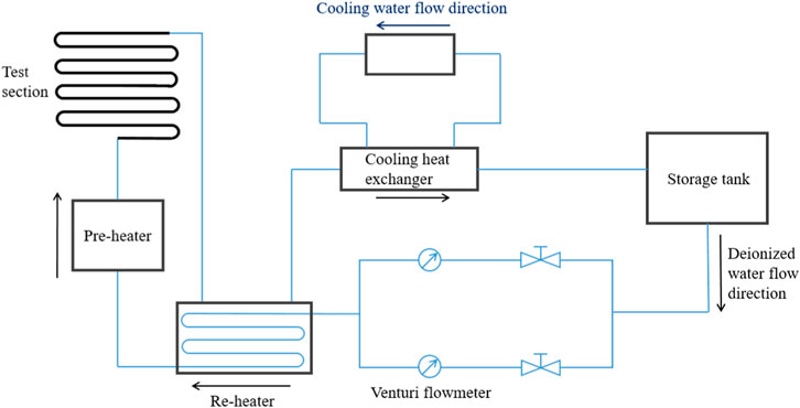
FIGURE 1. Schematic diagram of the experimental apparatus.

FIGURE 2. Schematic diagram of the temperature and pressure measuring point position.
Flow rate, pressure, and temperature were the three main parameters needed to be measured. The measuring accuracy of the Venturi flowmeter was 0.5. The pressure was measured using the differential pressure transmitter arranged along the helical tubes. Moreover, multiple armored N-type thermocouples were introduced to measure temperature at four different directions on the same measuring cross section, as shown in Figure 3.
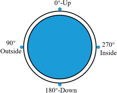
FIGURE 3. Schematic diagram of the measuring point position at the same cross section.
Parameters of helical tubes employed in the experiment are shown in Table 1. All helical tubes were made of S30408 stainless steel. The single-phase and two-phase experiments were carried out on each tube under different mass flow rates, heat flux, and pressure. The range of test condition was as follows: mass flow rate 100–1200 kg/(m2·s), pressure 2–7.6 MPa, and heat flux 100–500 kW/m2.
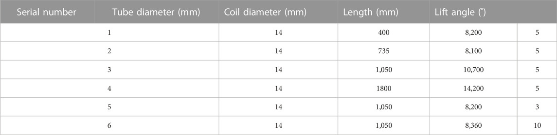
TABLE 1. Structural parameters of helical tubes.
2.2 Analysis methods
2.2.1 Typical reaction case analysis
The pressure drop of the steady flow in the helical tube consists of three parts: friction pressure drop, gravity pressure drop, and acceleration pressure drop:
Under the single-phase condition, the gravity pressure drop and acceleration pressure drop can be calculated as follows:
where
The single-phase friction pressure drop coefficient can be calculated as follows:
where Lij is the distance between i and j; and fc is the friction pressure drop coefficient.
Under the two-phase condition, based on the assumption of the homogeneous flow model, the gravity pressure drop and acceleration pressure drop can be calculated as follows:
where x is the void fraction.
The friction pressure drop of the two-phase flow could be expressed with a two-phase multiplier (Lockhart and Martinelli, 1949) based on the single-phase friction pressure drop coefficient:
where
2.2.2 Wall temperature and heat transfer coefficient
The calculation of wall temperature and heat transfer coefficient was processed on the following assumptions:
a. Ignore the axial heat conduction process.
b. The outside tube wall is insulated, and the whole heat conduction process is in the steady state.
c. The radial thermal conductivity stays constant.
Based on the aforementioned assumptions, the heat conduction process from the outside wall to the inside wall can be regarded as a two-dimensional steady heat conduction process. The heat conduction equation in polar coordinates is
The helical tube wall was divided into Ni × Nj blocks, and Eq. 8 was dispersed on the control body, as shown in Figure 4:
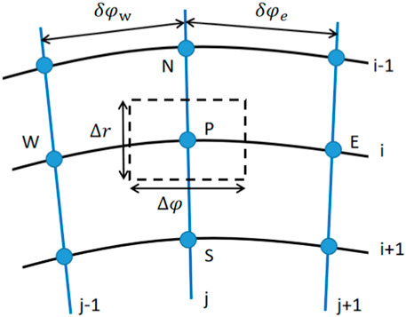
FIGURE 4. Schematic diagram of nodes.
where
The inside wall temperature of the tubes could be obtained by using the space node progression algorithm based on the measured outside wall temperature.
The resistivity of 304 stainless steel has a linear relationship with temperature in the experimental temperature range (Taler and Zima, 1999), which had been considered in the calculation of heat flux:
where qi is the heat flux at point i, W/m2; P is the heat power, W; I is the electricity, A; and η is the heating efficiency, which was obtained with the single-phase experiment before.
The average main flow enthalpy at the measurement point i can be calculated as follows:
where Hi is the enthalpy at point i, kJ/kg; and M is the mass flow rate, kg/s.
The main flow temperature at point i could be obtained from water property with pressure and enthalpy. Hence, the heat transfer coefficient can be calculated as
where hi is the heat transfer coefficient at point i, W/(m2·°C); Twi is the wall temperature inside the tube, °C; and Tfi is the main flow temperature, °C.
The heat transfer coefficient of each point on the same cross section (as shown in Figure 3) was switched to dimensionless h for the evaluation of circumferential heat transfer intensity:
where have is the average temperature of the cross section, which is calculated with the temperature at four section inner wall temperature.
It is worth mentioning that have is not equal to the average of hi at the four directions, and h* could reflect the relative value of the heat transfer coefficient of each side, to evaluate the heat transfer intensity.
3 Results and discussion
3.1 Friction pressure drop
Figure 5A shows the variation in the single-phase friction pressure drop with Re with different coil diameters. The friction coefficient fc of each tube is approximately negatively exponential with Re at Di<1800 mm, while the fc changes smoothly with Re at Di = 1800 mm. Moreover, the fc at Di = 1800 mm is smaller than that in other tubes at the same Re. This might be explained that helical tubes with large coil diameter has a similar flow pattern to the straight tubes, meaning that there is less secondary flow in large coil diameter tubes and smaller energy dissipation.
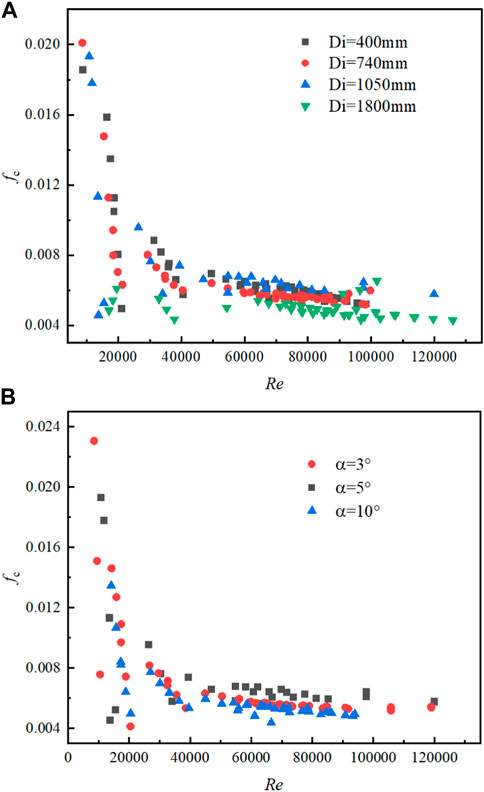
FIGURE 5. Variation in the single-phase friction pressure drop with Re. (A) Different coil diameters; (B) Different lift angles.
Figure 5B shows the variation in the single-phase friction pressure drop with Re at different lift angles. The friction coefficient of each tube is approximately negatively exponential with Re under the same coil diameter Di, which indicates that the lift angle has no significant effect on the friction pressure drop coefficient.
Figures 6A, B show the variation in the two-phase multiplier with void fraction x at different coil diameters and different lift angles, respectively, when p = 3.75 MPa and G = 405 kg/(m3·s). It could be seen that the two-phase multiplier shows a similar trend with the variation in the void fraction. A peak value of the two-phase multiplier appears at x = 0.75 when Di = 1800 mm, and a similar trend was reported by Santini et al. (2008).
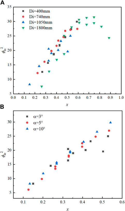
FIGURE 6. Variation in the two-phase friction pressure drop with Re. (A) Different coil diameters; (B) Different lift angles.
3.2 Single-phase circumferential non-uniformity characteristics
Figure 7 shows the variation in h* with a void fraction at different coil diameters when p = 3.75 MPa and G = 920 kg/(m3·s), and the heat transfer coefficient of the straight tube predicted by the Dittus–Boelter (D–B) equation (Heiss and Coull, 1951) is also provided. It can be seen that h* predicated by the D–B equation is smaller than 1.0, which confirms that the average heat transfer of the helical tube is stronger than that of the straight tube. Moreover, as the figure shows, the outside h* at the same cross section is the largest, while the up and down sides h* have similar values. The inside h* is the smallest and always less than the predicted value of the D–B equation. The outside h* decreases gradually with an increase in the coil diameter. When Di = 400 mm, the outside h* is more than 2.0, and the maximum h* is 2.58. When Di = 1800 mm, the outside h* decreases to less than 1.5, and the maximum h* is 1.35, which is 1.23 lower than that in the Di = 400 mm tube.
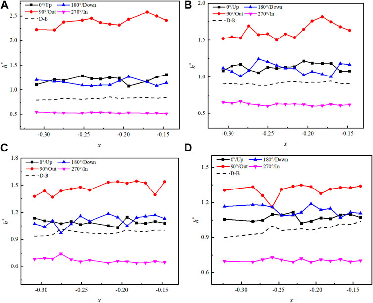
FIGURE 7. Variation in h* with a void fraction when p = 3.75 MPa and G = 920 kg/(m3·s). (A) Di = 400 mm; (B) Di = 735 mm; (C) Di = 1050 mm; and (D) Di = 1800 mm.
It might be explained from two points. One is that the cold fluid with higher density, affected by gravity and centrifugal force, tends to gather in the outside wall where the temperature difference between the outside fluid and wall is larger. The other is that the flow rate of the outside fluid is higher than that of the inside fluid, which benefits to improve the convection heat transfer. The smaller the coil diameter is, the stronger the centrifugal force effect on the fluid, meaning that the fluids with different temperatures and densities would be separated more completely. Hence, the phenomenon of larger outside h* at the same cross section is more obvious in the tubes with small coil diameter.
Figure 8 shows the variation in h* with a void fraction under different lift angle conditions when p = 3.75 MPa and G = 920 kg/(m3·s). It can be seen that the outside h* is the largest, and the inside h* is the smallest at different lift angles. Additionally, the maximum h* on the outside is 1.71 at α = 3°, which is only 0.17 higher than the maximum at α = 10°. The lift angle has no significant effect on the outside h*. It might be explained that the lift angle has slight influence on the distribution of fluid with different temperatures and densities, and the heat transfer coefficient in different directions was mainly affected by the coil diameter.
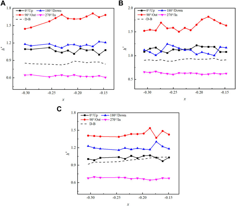
FIGURE 8. Variation in h* with a void fraction when p = 3.75 MPa and G = 920 kg/(m3·s). (A) α = 3°; (B) α = 5°; and (C) α = 10°.
3.3 Two-phase circumferential non-uniformity characteristics
Figure 9 shows the variation in h* with a void fraction under different coil diameter conditions when p = 3.75 MPa and G = 405 kg/(m3·s), and the heat transfer coefficient of the straight tube predicted by the Chen equation (Chen, 1962) is also provided. It can be seen that as the coil diameter increase from 400 to 1800 mm, the outside h* maintain the highest compared with h* in other three directions at the same cross section. This phenomenon is more significant at Di = 400 mm, and h* even exceeds 4.0 at x = 0.44, meaning that the outside h is four times the average h. Additionally, h* in each direction is higher than that predicted by the Chen correlation, except when x > 0.2 at Di = 400 mm.
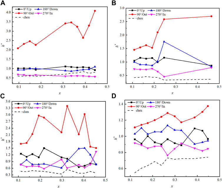
FIGURE 9. Variation in h* with a void fraction when p = 3.75 MPa and G = 920 kg/(m3·s). (A) Di = 400 mm; (B) Di = 735 mm; (C) Di = 1050 mm; and (D) Di = 1800 mm.
It might be explained that the density difference between the gas phase and liquid phase is larger than that in different liquid temperatures, and the gas tends to separate much completely from liquid under the same centrifugal force and gravity. Hence, the dense liquid gravitates to gather outside, and the bubble gravitates to gather inside, which leads to the significant difference of outside h* and inside h*. This phenomenon is weakened with the increase in the coil diameter contributing to the decrease in centrifugal force. The outside h* decreases to less than 1.4 when Di = 1800 mm.
Figure 10 shows the variation in h* with a void fraction under different lift angle conditions when p = 3.75 MPa and G = 405 kg/(m3·s). It can be seen that the lift angle shows no obvious regular influence on the distribution of h*. The similar opinion about the lift angle was proposed under single-phase conditions, further indicating that the lift angle is not the vital structural parameter affecting the temperature and heat transfer distribution in the helical tube.
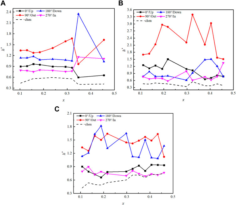
FIGURE 10. Variation in h* with the void fraction when p = 3.75 MPa and G = 920 kg/(m3·s). (A) α = 3°; (B) α = 5°; and (C) α = 10°.
3.4 Correlations between the friction pressure drop and heat transfer
3.4.1 Friction pressure drop
Figure11 shows the experimental single-phase friction pressure drop coefficient and the values predicated by the empirical correlations. It can be seen that fc-cal predicated by Ito (1959) and Srinivasan et al. (1968) all underestimates the experiment value when fc-exp >0.01, and there is still a maximum error of 81% (at fc-exp = 0.004, Srinivasan). The Blasius correlation was proposed with straight tube experiments, in which the predicated value is all smaller than the experimental value. The Ito and Srinivasan correlations were proposed with helical tube experiment, and different structural parameters and operating parameters might be the dominating factors contributing to errors.
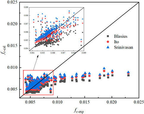
FIGURE 11. Comparison of the experimental value and the predicated value under single-phase conditions.
Based on the single-phase experimental pressure data, the correction of fc is shown in Eq. 14:
Figure 12 shows the experimental two-phase friction pressure drop coefficient and the values predicated by the empirical correlations. It can be seen that Hardik and Prabhu (2017) and Xiao et al. (2018) overestimated the pressure drop, while Ju et al. (2001) underestimated the pressure drop. Ju et al. found that the two-phase multiplier might be revised by the polynomial related to the void fraction:
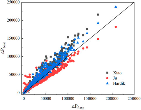
FIGURE 12. Comparison of the experimental value and the predicated value under two-phase conditions.
The mean error (ME), mean absolute error (MAE), and root mean square error (RMSE) were employed to evaluate the predicated value, which are calculated as follows:
The comparison between the predicated value and the experimental value is given in Table2 and Table3, respectively. It can be seen that the value calculated using Eq. 14 and Eq. 15 is more consistent with the experimental value, and the MAE and RMSE are smaller than the predicated value in the literature.
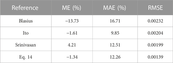
TABLE 2. Error between the experimental value and predicated value under single-phase conditions.
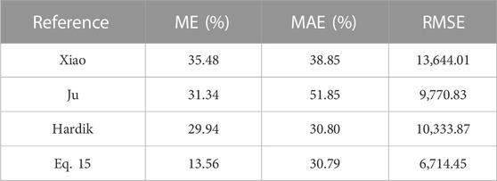
TABLE 3. Error between the experimental value and predicated value under two-phase conditions.
3.4.2 Heat transfer
Based on the classical D–B equation for a straight tube, considering the influence of the coil diameter and lift angle, the average heat transfer coefficient at the single phase could be fitted as follows:
However, according to the discussion on the circumferential non-uniformity of the aforementioned helical tubes, the heat transfer coefficient in different directions at the same cross section could be very different, and the outside h in small coil diameter tubes could reach 3–4 times the average heat transfer coefficient. Hence, only Eq. 20 cannot reflect the vital circumferential non-uniformity of the heat transfer in helical tubes. The factor λ was proposed to evaluate the circumferential heat transfer intensity, and it was considered to be the function of Re and diameter ratio Di/d:
Table 4 shows the deviation between the experimental value and the predicated value under single-phase conditions. It can be seen that the max MAE was 13.73%, while the max RMSE was 49.63.
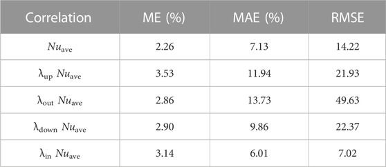
TABLE 4. Error between the experimental value and predicated value of Nu in different directions.
The λ fitted with experimental results in different directions is given as follows:
The modified Chen correlation considers that the saturated boiling heat transfer h in helical tubes could be divided into forced convection part hc and nucleate boiling part hNB:
Referring to the modified Chen correlation and the D–B equation, the forced convection hc is fitted as follows:
where
where
Table 5 shows the deviation between the experimental value and predicated value under two-phase conditions. It can be seen that compared with the modified Chen correlation, the value predicated by the correlation proposed by this paper is more consistent with the experimental value, of which the ME, MAE, and RMSE are greatly improved.
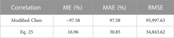
TABLE 5. Error between the experimental value and predicated value of Nu under two-phase conditions.
The correlations proposed in this paper have an applicable parameter range of Di/d = 28.6–128.6, G = 200–1,000 kg/(m2. s), and P = 2–7.6 MPa.
4 Conclusion
In order to study the flow resistance and the non-uniform characteristics of circumferential heat transfer in helical tubes, the experiments of helical tubes with different coil diameters and lift angles were carried out under single-phase conditions and saturated boiling two-phase conditions. The friction pressure drop and circumferential heat transfer coefficient were analyzed, and the empirical correlations of heat transfer and flow resistance were obtained based on the experimental results. The following conclusions were obtained:
(1) Increasing coil diameter is conducive to reducing the flow resistance, while the lift angle has no significant effect on the friction pressure drop.
(2) The outside heat transfer coefficient is the maximum at the same cross section, and the inside heat transfer coefficient is the minimum, which is more obvious under two-phase conditions or in the tubes with a small coil diameter.
(3) The lift angle has no obvious effect on circumferential heat transfer non-uniformity.
(4) λ was proposed to present the circumferential non-uniformity in helical tubes, which was fitted with the single-phase experimental results.
(5) Based on the experimental results of single-phase conditions and two-phase conditions, the flow resistance correlation and the heat transfer correlation are fitted, respectively.
Data availability statement
The original contributions presented in the study are included in the article/Supplementary Material; further inquiries can be directed to the corresponding author.
Author contributions
XL and YoH contributed to the conception. YM and YiH contributed to methodology. YG and XZ organized the database and performed the statistical analysis. XZ wrote the first draft of the manuscript. DJ and XZ wrote sections of the manuscript. All authors contributed to the article and approved the submitted version.
Funding
This research was funded by the National Natural Science Foundation of China (grant numbers U20B0211 and 52171085) and Department of Science and Technology of Guangdong Province (grant number 2017B020242001).
Conflict of interest
Authors XZ, XL, YG, DJ, YiH, YoH, and YM were employed by the company China Nuclear Power Technology Research Institute Co., Ltd.
Publisher’s note
All claims expressed in this article are solely those of the authors and do not necessarily represent those of their affiliated organizations, or those of the publisher, the editors, and the reviewers. Any product that may be evaluated in this article, or claim that may be made by its manufacturer, is not guaranteed or endorsed by the publisher.
References
Chen, J. C. (1962). Correlation for boiling heat transfer to saturated fluids in convective flow. Ind. Eng. Chem. Process Des. Dev. 5, 322–329. doi:10.1021/i260019a023
Chen, S., Hu, Z., Xiao, Y., and Gu, H. (2018). Experimental investigation of subcooled flow boiling heat transfer in helical coils. Nucl. Eng. Des. 327, 187–197. doi:10.1016/j.nucengdes.2017.12.014
Chung, Y.-J., Kim, H. J., Chung, B.-D., Lee, W. J., and Kim, M.-H. (2013). Thermo-hydraulic characteristics of the helically coiled tube and the condensate heat exchanger for SMART. Ann. Nucl. Energy 55, 49–54. doi:10.1016/j.anucene.2012.11.026
Fsadni, A. M., and Whitty, J. P. M. (2016). A review on the two-phase heat transfer characteristics in helically coiled tube heat exchangers. Int. J. Heat Mass Transf. 95, 551–565. doi:10.1016/j.ijheatmasstransfer.2015.12.034
Hardik, B. K., Baburajan, P. K., and Prabhu, S. V. (2015). Local heat transfer coefficient in helical coils with single phase flow. Int. J. Heat Mass Transf. 89, 522–538. doi:10.1016/j.ijheatmasstransfer.2015.05.069
Hardik, B. K., and Prabhu, S. V. (2017). Boiling pressure drop and local heat transfer distribution of helical coils with water at low pressure. Int. J. Therm. Sci. 114, 44–63. doi:10.1016/j.ijthermalsci.2016.12.004
Heiss, J. F., and Coull, J. (1951). Nomograph of dittus-boelter equation for heating and cooling liquids. Industrial Eng. Chem. 43, 1226–1229. doi:10.1021/ie50497a060
Ito, H. (1959). Friction factors for turbulent flow in curved pipes. Trans. ASME. J. Basic Eng. 81, 123–132. doi:10.1115/1.4008390
Ju, H., Huang, Z., Xu, Y., Duan, B., and Yu, Y. (2001). Hydraulic performance of small bending radius helical coil-pipe. J. Nucl. Sci. Technol. 38, 826–831. doi:10.1080/18811248.2001.9715102
Kong, L., Han, J., Chen, C., Xing, K., and Lei, G. (2017). An experimental study on subcooled flow boiling heat transfer characteristics of R134a in vertical helically coiled tubes. Exp. Therm. Fluid Sci. 82, 231–239. doi:10.1016/j.expthermflusci.2016.11.023
Lockhart, R. W., and Martinelli, R. C. (1949). Proposed correlation of data for isothermal two-phase two-component Flow in Pipes. Chem. Eng. Proc. 45.
Naphon, P., and Wongwises, S. (2006). A review of flow and heat transfer characteristics in curved tubes. Renew. Sustain. Energy Rev. 10, 463–490. doi:10.1016/j.rser.2004.09.014
Nariai, H., Kobayashi, M., and Matsuoka, T. (1982). Friction pressure drop and heat transfer coefficient of two-phase flow in helically coiled tube once-through steam generator for integrated type marine water reactor. J. Nucl. Sci. Technol. 19, 936–947. doi:10.1080/18811248.1982.9734239
Santini, L., Cioncolini, A., Lombardi, C., and Ricotti, M. (2008). Two-phase pressure drops in a helically coiled steam generator. Int. J. Heat Mass Transf. 51, 4926–4939. doi:10.1016/j.ijheatmasstransfer.2008.02.034
Seban, R. A., and Mclaughlin, E. F. (1963). Heat transfer in tube coils with laminar and turbulent flow. Int. J. Heat Mass Transf. 6, 387–395. doi:10.1016/0017-9310(63)90100-5
Srinivasan, P. S., Nandapurkar, S. S., and Holland, F. A. (1968). Pressure drop and heat transfer in coils. Chem. Eng. 218, 113–119.
Taler, J., and Zima, W. (1999). Solution of inverse heat conduction problems using control volume approach. Int. J. Heat Mass Transf. 42, 1123–1140. doi:10.1016/s0017-9310(98)00280-4
Vashisth, S., Kumar, V., and Nigam, K. D. P. (2008). A review on the potential applications of curved geometries in process industry. Industrial Eng. Chem. Res. 47, 3291–3337. doi:10.1021/ie701760h
Keywords: helical tube, circumferential distribution, heat transfer, pressure drop, two-phase flow
Citation: Zheng X, Lu X, Gao Y, Jin D, Hu Y, Hu Y and Mao Y (2023) Experimental study on friction pressure drop and circumferential heat transfer characteristics in helical tubes. Front. Energy Res. 11:1204850. doi: 10.3389/fenrg.2023.1204850
Received: 12 April 2023; Accepted: 24 May 2023;
Published: 13 June 2023.
Edited by:
Xiongbo Duan, Central South University, ChinaReviewed by:
Ruikun Wang, North China Electric Power University, ChinaHui Liang, Harbin Engineering University, China
Copyright © 2023 Zheng, Lu, Gao, Jin, Hu, Hu and Mao. This is an open-access article distributed under the terms of the Creative Commons Attribution License (CC BY). The use, distribution or reproduction in other forums is permitted, provided the original author(s) and the copyright owner(s) are credited and that the original publication in this journal is cited, in accordance with accepted academic practice. No use, distribution or reproduction is permitted which does not comply with these terms.
*Correspondence: Xianghui Lu, eC56aGVuZy50eUBmb3htYWlsLmNvbQ==