- 1Department of Electrical Engineering, Sukkur IBA University, Sukkur, Sindh, Pakistan
- 2Department of Electrical Engineering, College of Engineering, King Saud University, Riyadh, Saudi Arabia
- 3Energy and Climate Change Division, Sustainable Energy Research Group, Faculty of Engineering and Physical Sciences, University of Southampton, Southampton, United Kingdom
Modular multilevel converter (MMC) is a proven technology for HVDC applications due to its salient features such as modularity and excellent power quality. To ensure best possible grid support, recent grid codes require incorporating fault ride-through (FRT) strategies so that HVDC converter stations remain connected and maintain reliable operation under various symmetrical and asymmetrical AC faults. In this paper, a communication-free enhanced fault ride-through technique without the need of DC chopper has been proposed. The proposed FRT strategy ensures quick post fault recovery operation and can effectively manage DC link and capacitor voltages within safe limits. Along with proposed FRT strategy, in order to avoid high circulating current (CC) inside an MMC, this paper has proposed an optimal circulating current control approach based on proportional resonant and PI controllers in an abc reference frame. The suggested technique lowers the ripple in capacitor voltages while reducing the magnitude of the CC. Under both balanced and unbalanced ac grid conditions, the ripple in the dc link voltage is also reduced without the use of dual synchronous reference frame or any additional controllers. Simulation results confirm the effectiveness of the proposed FRT and CC suppression techniques for a 580-kV, 850-MW MMC-based HVDC system.
1 Introduction
Since power electronic devices and power converters have advanced so quickly, DC has reemerged and become preferable to AC. HVDC is a well-established technology that is chosen over HVAC for long-distance transmission (Soomro et al., 2022). Lists the MMC-based HVDC installations that have already been established around the world. The growth of HVDC projects has created the possibility for HVDC super-grids, which connect several HVDC systems. Continental super-grids are regarded as futuristic and are anticipated to materialize in 15 years (Gomis-Bellmunt et al, 2019).
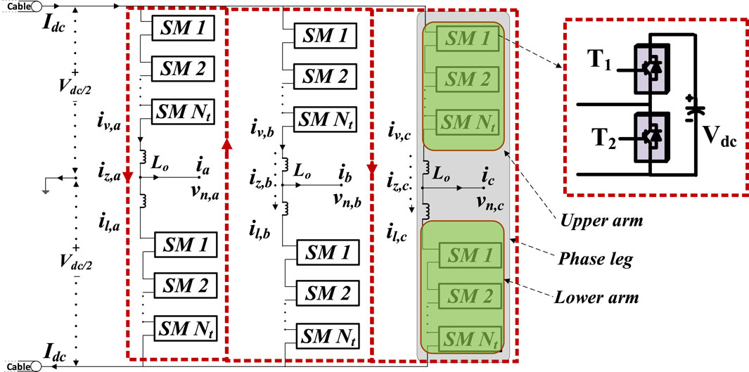
Different converter configuration have been employed in several HVDC projects. They are majorly classified into Line-commutated converters (LCC) and voltage source converter (VSC). Initially LCC were considered favored option. However, the voltage source converter (VSC) afterwards appeared and is dominating. MMC is recognized to be advanced version of VSC technology as shown in Figure 1. Due to key advantages such as scalability, modularity, FRT capability, improved power quality, compactness, black start capability, and better efficiency, MMC is preferred over other VSC topologies (Soomro et al., 2022).
Numerous PWM approaches, including sinusoidal pulse width modulation (SPWM), space vector PWM, selective harmonic elimination (SHE), and nearest level modulation (NLM), are suggested in the literature as being utilized to control the MMC. NLM operates at fundamental switching frequency (reduces switching losses) and is simple to implement (Ali et al., 2020; Soomro et al., 2021). NLM is favored among all PWM approaches for a greater number of sub-modules. Additionally, it provides desirable benefits including a natural voltage balancing method and avoids the need for challenging mathematical calculations, as in the case of SHE (Chandio et al., 2023). Due to the aforementioned advantages, NLM has been selected in the proposed system as a PWM.
In MMC-based HVDC systems, the issues of CC and capacitor voltage ripple (CVR) need to be closely examined. During MMC operation, the SMs capacitors will charge and discharge, which will cause a CVR issue. This could result in energy differences between the arms in a MMC. The potential difference (imbalance voltage) and internal current between the various phase legs and arms are brought on by this energy difference. CC, also known as internal current is shown in Figure 1 with red dotted lines. Under balanced grid settings, a CC is a negative sequence current with twice the fundamental frequency. However, along with negative sequence current, positive and zero-sequence current also show up in unbalanced grid situations (Cui et al, 2018). Although second order harmonics predominate in CC, if left unchecked, it may intensify 4th, 6th, 8th order harmonics and beyond. Furthermore, if unchecked, it could lead to higher CVR problem, power losses, poor power quality, inductor saturation, decreased efficiency, shorter equipment life, and general instability (Cui et al, 2015).
This research paper presents an integrated control strategy that not only suppresses CC but also tackles the issue of CVR. Through simulation results, we demonstrate that the proposed controller outperforms conventional PI and PR-based CC suppression methods in terms of dynamic response, steady-state error reduction, and converter loss mitigation. Additionally, the proposed method ensures well-regulated capacitor voltage across all arms of MMC, offering superior performance during fault conditions and maintaining stable converter operation. In addition to reduced CC and CVR, a communication-free enhanced FRT technique without the need for a DC chopper has also been proposed in this research work.
2 Comparison with previous research
CC suppression and capacitor voltage balancing approaches have been the subject of extensive investigation. In research work (Ud Din et al., 2019; Ishfaq et al, 2019; Uddin et al., 2019; Uddin et al, 2021) different CC suppression schemes have proposed for CC suppression. In (Uddin et al, 2021), authors proposed arm level control for controlling output and CC of MMC using vector current control principle. The CC is suppressed by using conventional proportional resonant (PR) controller. The validity of the suggested arm level control scheme is demonstrated in the paper by comparison findings of leg-level control based on PR controller. A three-phase, five-level MMC is proposed to evaluate how well the suggested CC approach works. It was suggested in (Ud Din et al., 2019) that a backstepping controller may be used to regulate the capacitor and CC voltage. Comparing the proposed backstepping controller to a PR controller, it was discovered that the backstepping controller outperformed the PR controller in terms of CC suppression and CVR reduction. The output current and CC are controlled using an adaptive proportional integral (API) controller in (Ishfaq et al, 2019). Results from MATLAB/Simulink are then compared for the PR and API controllers to demonstrate that the API controller outperform the PR controller in terms of suppressing CC. The sliding mode control (SMC) in (Uddin et al., 2019) is used to control the output current and CC. To confirm the effectiveness of the suggested control technique for suppressing CC, the results of the suggested controller are extensively compared with the traditional PR controller. On a unit-level MMC, each of the aforementioned methods for suppressing CC has been put into practice. However, their integration into networked systems like HVDC is not covered. Additionally, the suggested control methods’ resilience has not been examined in the context of various AC and DC fault scenarios. Sub-module (SM) CVR and CC reduction will become even more challenging in case of unbalanced grid conditions (AC fault). The CVR and CC can be rather significant and can exceed the established safe limits in case of unbalanced AC fault. If this happens, the converter will trip, which could cause major stability issues. Various strategies for addressing the MMC SM CVR and CC under unbalanced grid situations have been presented in literature (Ilves et al, 2011; Pou et al., 2014; Wang et al, 2018a; Li et al, 2019a; Wang et al, 2020a; Wang et al., 2020b; Wang et al, 2020c; Wang et al, 2021). The goal of the suggested compensation control strategies is to guarantee that, even when the grid is unbalanced, the CVR and CC of MMCs always operate within safe limits. However, the authors have only proposed control techniques for internal dynamic control of MMC such as CC and CVR. The studies presented did not focus the implementation of outer loop. Results were only limited to control of CC and CVR on a unit level MMC and transient analysis under different AC and DC faults were not part of the studies.
Traditional CC suppression schemes only focus on reducing CC without minimizing CVR. On the other hand few researchers prefer lowering CVR while slightly compromising CC. To suppress the CC and decrease the CVR simultaneously, several authors have proposed various enhanced CC control methods (Wang et al., 2018b; Hafeez et al, 2020; Isik et al, 2020; Hafeez et al, 2021; Isik et al, 2021). The research work in (Isik et al, 2020; Isik et al, 2021) focus on internal dynamics under only single-line-to-ground (SLG) fault on a MMC-HVDC test system. The robustness of the proposed HVDC is not tested against other AC fault scenarios such as symmetrical and asymmetrical faults. Whereas (Wang et al., 2018b; Hafeez et al, 2020; Hafeez et al, 2021) only limits the results for CC and CVR reduction, without verifying the behavior of proposed HVDC system for AC and DC fault scenarios.
The transient dynamics of HVDC systems during various AC and DC fault scenarios is also active research area. The HVDC system is considered to be robust if it has both AC FRT capability and internal dynamics control. Numerous researchers have suggested alternative control and protection measures, including those in (Zhou et al, 2019; Luscan et al, 2020; Malanda, 2020; Shah et al, 2020; Cheng et al, 2021; Xin et al, 2021), for the HVDC system’s ability to ride through an AC fault. The severe requirement of FRT for safe grid operation during faults with minimal power disruptions is the driving factor behind these problems. At the point of common connection (PCC) between the MMC stations and the faulty grid during the occurrence of a grid fault, there is a significant voltage drop. The output power of the MMC abruptly decreases as a result of this quick drop in AC voltage. The HVDC power mismatch results from the fact that one MMC fails to interchange power with the faulty grid while the other MMC, which is situated on the other side of the DC link, is still able to perform well (Tavakoli et al, 2021). Depending on the fault location (grid 1 or grid 2) and the pre-fault power direction, the capacitance of the DC cable is continually charged or discharged. During the fault, if the capacitance is not adequately managed, this can cause the DC voltage to rise or drop to an unacceptable level. This puts more strain on the HVDC equipment and may cause protective devices to trip; which would result in the converter station being disconnected from the AC grid too soon. To ensure the best possible grid support, current grid regulations mandate that HVDC converter stations remain connected to the grid and maintain stability under such PCC fault situations. The HVDC converter station’s FRT capabilities help to achieve this goal (Tzelepis et al, 2017; Wang et al, 2017).
For grid faults, a variety of FRT techniques have been proposed to keep DC voltage within acceptable limits. The most of them are with offshore wind (OW) penetration, where a DC over voltage results from an OW farm’s excess output and an issue with the onshore AC grid (Erlich et al, 2013; Kirakosyan et al., 2016; Li et al, 2019b). The following categories can be applied to the FRT procedures depending on how this excess power is managed.
a. Dissipation: A DC chopper is used to dissipate excess power generated during a brief time of fault (Pannell et al, 2013; Naderi et al, 2018). (Xu et al, 2019; Xu et al, 2020; Qi et al, 2021; Wu et al, 2021; Wang et al, 2023) proposed novel and enhanced DC chopper for MMC base(B)d HVDC applications.
b. Storage: Kinetic energy is produced out of the excess energy and kept in the rotor of the wind turbine (Yang et al, 2011) or a special flywheel (Daoud et al, 2015).
c. Power reduction: The excess power is decreased through the following methods: i) power reduction of individual OW turbines during onshore fault (Ramtharan et al, 2009), ii) reduction of the OW AC voltage by the offshore MMC (Erlich et al, 2013), and iii) an increase in the frequency of the AC voltage by the offshore MMC, which results in a reduction in OW power (Silva et al, 2014).
From the FRT design perspective, the interconnection of two AC grids present a unique set of challenges because the fault could occur in either grid or grid 2. As a result, the DC link may experience both DC under and over voltage. Be aware that while DC under voltage might cause over modulation problems (Jiang et al, 2023), DC overvoltage may have an impact on the HVDC equipment’s insulation level and MMC parts. Typically, slave MMC (referred to as MMC2) regulates the active power flow while master MMC (referred to as MMC 1) acts in DC voltage regulation (Wang et al, 2014). Therefore, 2 MMCs require different FRT mechanisms in order to stabilize DC voltage during fault.
Some of the recommended FRT systems, which focus on the connecting of two AC grids, depend on a communication channel. For instance, the research reported in (Adam et al, 2010) found that the observed PCC voltages on both sides of the DC link determine the active power set point of the slave terminal. As a result, the active power reference is automatically lowered if there is a voltage dip on either side of the DC link. The implementation of a communication link typically results in good DC voltage performance, but requires extra cost and there is a chance that communication may fail. The ability of master and slave stations to momentarily switch between performing DC voltage regulation is the basis for another class of FRT techniques. With these methods, communication between two MMC terminals is nonexistent. Similarly, the idea of voltage margin control has been proposed in (Nakajima and Irokawa, 1999). When the system experiences an abnormal DC voltage state, the slave converter station detects it and shifts from active power controller to DC voltage controller till everything returns to normal. As an alternative to voltage margin control, DC voltage droop control has been studied in (Oguma and Akagi, 2016) to regulate the DC link during a fault. A control technique to reduce transient voltage dips (AC FRT) for HVDC systems based on MMC was put forth in (Slettbakk, 2018; Hoehn et al., 2019; Khan et al, 2022). The objective was to use internal energy stored in MMC to supply the passive loads with steady power in the case of any dip at the grid. However, the studies were limited to only voltage sag fault and system stability were not tested against other different fault scenarios such as symmetrical, asymmetrical faults. Moreover, the CC and CVR problem were not focused. The same FRT approach has been extended for MTDC systems in (Ansari et al., 2022). The key drawback of proposed FRT in (Slettbakk, 2018; Hoehn et al., 2019; Ansari et al., 2022; Khan et al, 2022) is increased size of capacitor, increasing overall cost and weight of converter station.
The aforementioned issues are addressed in this study in such a way that not only does the HVDC link’s DC voltage is managed, but also the CC and CVR is successfully suppressed. In order to avoid high CC inside an MMC, this paper suggests an optimal CC control approach based on PR and PI controllers in an abc reference frame. The suggested technique lowers the CVR while reducing the magnitude of the CC. Under both balanced and unbalanced ac grid conditions, the ripple in the DC link voltage is also reduced without the use of dual synchronous reference frame (DSRF) or any additional controllers. Moreover, a communication-free improved voltage margin FRT technique without the need of DC chopper has been proposed. The capacitor and DC link voltages stay within safe limits during the FRT, and the DC voltage never exceeds the safe limit. Research is carried out on the efficacy of the proposed FRT and CC suppression techniques for symmetrical and asymmetrical faults at different fault locations (Grid 1 and 2).
3 Proposed enhanced CC suppression scheme and optimized voltage margin control
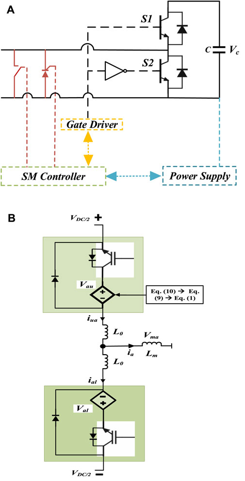
Although there are many other MMC SM configurations, the half-bridge is frequently used. The Half Bridge SM, seen in Figure 2A, is used in this study due to its low cost, reduced volume (weight) and simple controllability (Isik et al, 2020; Isik et al, 2021). In a half bridge SM, the SM capacitor is inserted into the arm, and if the top switch S1 conducts, the SM voltage changes to the capacitor voltage. The SM voltage is zero when the lower switch, S2, conducts. As a result, average arm voltage, which is composed of N separate SM voltages as shown in Figure 2B, can be thought of as a controlled voltage source (Isik et al, 2020; Isik et al, 2021).
Upper (Vau) and lower (Val) arm voltages can be expressed Eqs 1, 2 if KVL is applied to phase A in Figure 1; Eq. 3 can be used to construct a reference voltage for the output ac voltage for Phase A, where m is the modulation index, w is the angular frequency, and δx is the system’s initial phase angle; Eq. 4 represents phase voltage. The expressions for the arm currents of the upper (iu,a), lower (il,a), and differential current (iz,a) are (5), (6), and (7), respectively. As can be seen from Eq. 7 that differential current consists of dc component and ac component of CC. DC component is essential for reliable operation of the converter, however the CC need to be suppressed. If left uncontrolled, it will increase ripple component (Δvripple,ua) of SM upper arm capacitor voltage as expressed in Eq. 8. Therefore the primary job of proposed CC is to suppress icirc,a sin (nwt + ϕy) and (Δvripple,ua) simultaneously. Eq. 9 describes individual SM current. It can be seen from Eqs 10, 11 that total power and energy consists of even harmonics and switching frequency components. These components can be removed and the energy variation can be decreased through proper control of the CC. The transfer function of proposed CC suppression PR control is expressed in Eq. 12. In order to achieve symmetric operation throughout all phases, a compensating voltage is applied to the suppressed differential voltage (vz,ac) to provide a consistent imbalance voltage. Thus, CC is reduced by suppressing this differential voltage (imbalance voltage). Thus, Eqs 13, 14 for the upper and lower arms, respectively, can be used to estimate the number SM to be inserted, where (nz) is the differential insertion index and determined by the reference differential voltage vz,a∗.
Figure 3 shows the proposed CC control technique. The work in this research is based on an enhanced CC suppression strategy. As a result of this method’s elimination of DSRF and dependence on PLL, the controller’s processing time is reduced, making it faster. At twice the fundamental frequency, it can reduce the positive, negative, and zero sequence components of the CC. The suggested approach of controlling the CC avoids ripple components from entering the dc connection without any additional controller.
With coordination between two terminals and the use of the DC link voltage as a reference signal, enhanced AC FRT is presented. With the proposed AC FRT scheme, the use of DC chopper and direct communication between two stations can be avoided. In fact, the idea of voltage margin control was initially put forth in (Nakajima and Irokawa, 1999), which was a development of the LCC-HVDC’s current margin control (Cui et al, 2014). Figure 4A shows the LCC-current margin control principle (Cui et al, 2018). In the LCC-HVDC, the rectifier controls the line current and the inverter controls the DC link voltage. When there is a fault in the grid on the rectifier side, the rectifier loses its capacity to control the line current, and the inverter assumes control over line current regulation. Figure 4B illustrates the voltage margin basic operating concept (Cui et al, 2018). If the master station fails to control the dc voltage due to fault on the ac grid side, then the slave station has to take over the responsibility of DC link regulation.

FIGURE 4. (A) V-I Characteristics in LCC based HVDC system (B) Voltage Margin control in VSC based HVDC system.
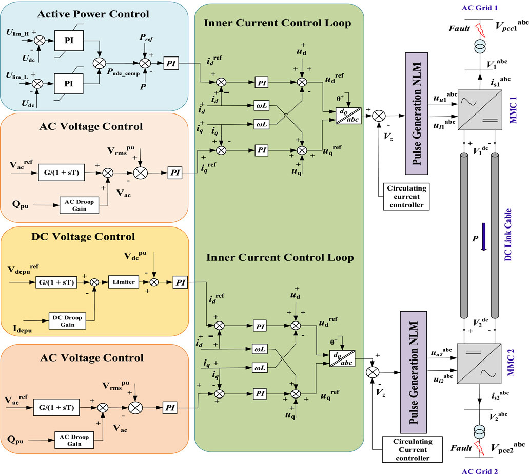
Optimized DC voltage margin control has been implemented to ensure robust AC FRT as shown in Figure 5 under proposed system description section. It will momentarily lose control of the DC voltage in the event of a fault at the AC Grid station (connected to the DC voltage control). When DC voltage disturbances reach the threshold DC voltage, the slave station can immediately take over the regulation of the DC voltage without the requirement to determine the type and depth of the AC fault. Under normal operating circumstances, the active power control station helps to stabilize the power at reference power while the dc voltage control regulates the dc voltage at reference value. The DC link voltage hits either the maximum threshold (Ulim_H) or the minimum threshold (Ulim_L) in the case of a fault. As a result, the active power control station regulates its own power level in order to stabilize the dc voltage.
4 Proposed system description
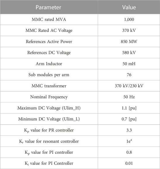
To verify the effect of proposed enhanced CC suppression scheme and optimized AC FRT strategy, the interconnection of two AC grids via MMC-HVDC system was studied on a PSCAD/EMTDC software. The detailed control system applied on MMC 1 and MMC 2 station on a point to point grid connected HVDC system is shown in Figure 5. The control system includes active power control, dc voltage control, alternative voltage control, CC suppression control, NLM control, and inner current control. A widely used SRF approach is used. The SRF scheme’s mathematical equations and implementation procedure are fully explained in (Adam et al, 2010; Silva et al, 2014; Wang et al, 2014; Jiang et al, 2023). The objective of the developed control system is to manage DC and AC voltages at the MMC1 converter station while active power and AC voltage are controlled at the MMC2 converter station. Furthermore, to guarantee a low CC and a balanced SMs capacitor voltage, the proposed CC suppression control is employed at both MMC converter stations. Finally, optimized AC FRT scheme has been implemented to ensure robust AC FRT during various symmetrical and asymmetrical ac faults. The parameters used in proposed system is described in Table 1.
Essentially, the control mechanism consists of two control loops: outer control loops and inner control loops. The outer loop controls either active power or DC voltage, as well as AC voltage or reactive power. The output from the outer control loop, which includes idref and iqref, is supplied to the inner loop, serving as the reference signal for the inner current control loop. In the proposed system description, outer control loops for MMC1, including active power and AC voltage control, provide idref and iqref to the inner current control loop. On the other hand, for MMC2, outer control loops such as DC voltage and AC voltage control deliver idref and iqref to the inner current control loop. In the inner current control loop, the actual values of id and iq are compared with the reference signals, such as idref and iqref, and the error is fed to a PI controller, which minimizes the error. The output of the inner controller is further fed to the NLM for generating gate pulses for the MMC.
The control loops, including the active power control loop, AC voltage control loop, DC voltage control loop, and inner current control loop, can be represented by Eqs 15–18 respectively.
5 Case studies
Multiple fault scenarios must be addressed by an effective FRT mechanism. The robustness of system has been tested against various fault types such as three phase fault (LLL-G), SLG fault, line to line (LL) and double-line-to-ground (LLG) fault. All the scenarios cannot be covered in this paper. As a result, this section presents a detailed evaluation of two chosen fault scenarios.
• Scenario 1: The LLL-G fault happens at AC grid 2 at t = 3 s and cleared at t = 3.3 s.
• Scenario 2: The SL-G occurs at AC grid 1 at t = 3 s and cleared at t = 3.3 s.
5.1 Simulation results for scenario 1 at AC grid 2 connected to MMC 2
On the AC side of MMC converter station 2, LLL-G symmetrical fault is simulated in order to assess how well proposed AC FRT strategies operate. In this part, the simulation results for both of the converter stations are discussed. The fault has a total duration of 0.3 s (300 milliseconds). It is switched at time t = 3 s and is supposed to be cleared at time t = 3.3 s. The FRT mechanism are influenced by the direction of the prefault power flow via the HVDC link. Here, it is assumed that the direction of the positive power flow is from MMC 1 to MMC 2 station. The excess power in the DC link causes DC over voltage when a failure in AC grid 2 happens and the power flow direction prior to the fault is positive. Figure 6A shows simulation results for DC link voltages at both MMC terminals. The proposed CC suppression scheme has been employed, which ensures smoother DC link voltages. Without using an additional controller, the proposed CC control method avoids ripple components from entering the DC link voltages at MMC 1 and MMC 2 station. It has been shown in Figure 6D that throughout the fault period, the phase voltages at terminal 2 (connected to MMC 2) drops to zero. While MMC 1, which is connected to AC grid 1, has no significant impact on their phase voltages as shown in Figure 6C, regardless of whether a fault occurs at AC Grid 2, which is connected to MMC 2. As the phase voltages at terminal 2 collapse during a fault, it is evident in Figure 6B that the power supplied by MMC 2 drops to zero. The proposed AC FRT scheme performs in a robust way by reducing the power by MMC 1 to zero as soon as the maximum DC voltage (Ulim_H) is detected as shown in Figure 6.
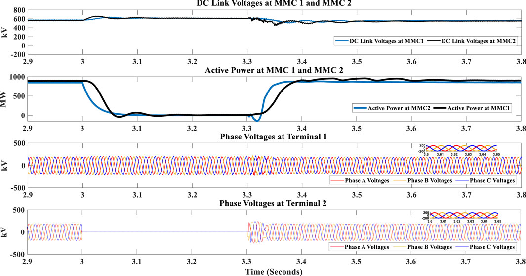
FIGURE 6. (A) DC Link Voltages at MMC 1 and MMC 2 (B) Active Power at MMC 1 and MMC 2 (C) Phase Voltages connected to MMC 1 (D) Phase Voltages connected to MMC2.
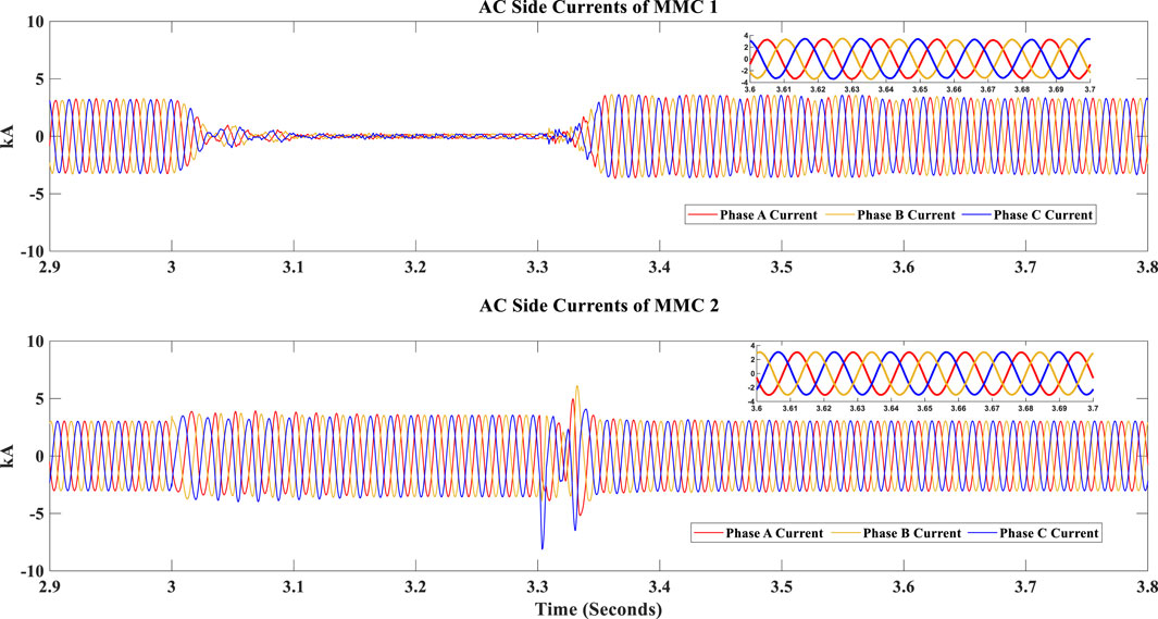
The phase voltages (connected to MMC 2) drops to zero during the entire fault period, and the MMC 2 converter station contributes limited current to the fault as shown in Figure 7B. Therefore, the proposed AC FRT ensures reduced di/dt stress on the power semiconductor devices. Moreover, it can be seen from Figure 7A that during the entire fault, the MMC 1 station reduces the current to zero so that power imbalance and dc overvoltage can be avoided. The phase voltages and AC side currents of MMC 1 and MMC 2 have improved power quality and reduced THD following IEEE standards, as shown in zoomed-in portion of Figures 6, 7.
The proposed MMC-based HVDC system not only ensures optimized AC FRT but also manages CC and CVR issues. The proposed CC scheme successfully suppresses the magnitude of the CC, as shown in Figure 8A. The magnitude of the differential current is 0.5 PU, which is less than 10% of the nominal current according to grid codes. The simulation results of the proposed controller are compared with conventional PI and PR-based CC suppression control methods to validate the effectiveness of the suggested control strategy. The proposed controller achieves a quicker dynamic response and reduces steady-state error in comparison. The proposed CC controller ensures the efficient suppression of the second harmonic current in each leg of the converter, leading to decreased converter losses and reduced current stresses on the switches. Figure 8 shows the dynamic response of CC using the proposed controller, along with PI and PR controllers. The response of the proposed CC controller is swift and effective, reaching a steady state at nearly 3.6 s (within 0.3 s after the fault disappears), while the PI and PR controllers attain a steady state at approximately 3.7 s (within 0.4 s after the fault disappears). This indicates that the proposed CC method responds more quickly than the PI and PR in terms of circulating current control. The efficiency of the proposed CC controller is maintained in the steady state as well. The CC current converges perfectly at the reference value in the case of the proposed method, while the PI and PR controllers fail to fully suppress the second harmonic current, as shown in Figures 8B, C respectively. This leads to increased converter losses and current stress in devices with the same size and rating as the converter. Lastly, Figure 8 clearly demonstrates that the response of the proposed CC method is significantly better than the PI and PR-based CC methods during a fault. The PI and PR-based methods display inferior performance during the fault, and when the fault occurs at 3 s, the differential current reaches 1.8 PU.
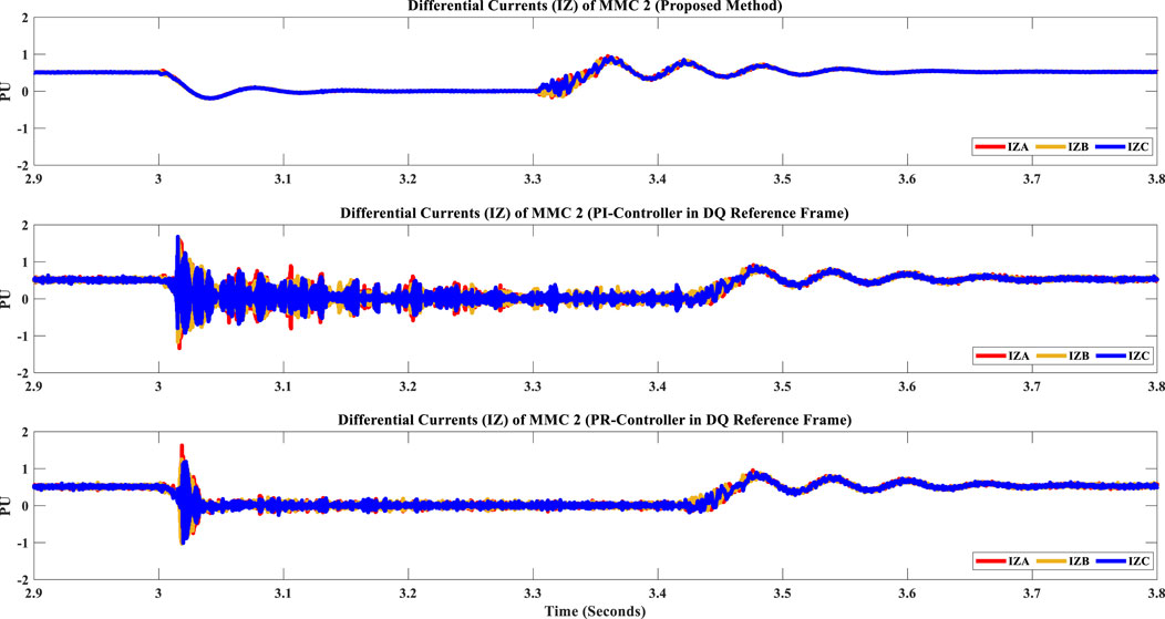
FIGURE 8. Differential Currents of MMC 2: (A) proposed controller (B) PI controller (C) PR controller.
As depicted in Figure 9A, the proposed control strategy not only suppresses CC but also addresses the issue of CVR. The CVR of MMCs consistently operates within safe limits throughout the fault, preventing the converter from tripping. Moreover, the capacitor voltages are balanced and display a reduced CVR during and after the fault. Figures 9B, C illustrate the capacitor voltage in the case of the PI and PR-based CC controllers, respectively. Both the PI and PR-based CC suppression schemes focus solely on reducing CC without minimizing CVR. Consequently, the ripple magnitude of capacitor voltages in both methods is nearly the same (higher). In comparison to the PI and PR-based methods, the proposed method ensures well-regulated capacitor voltage for all upper and lower arms of MMC, as seen in Figure 9.
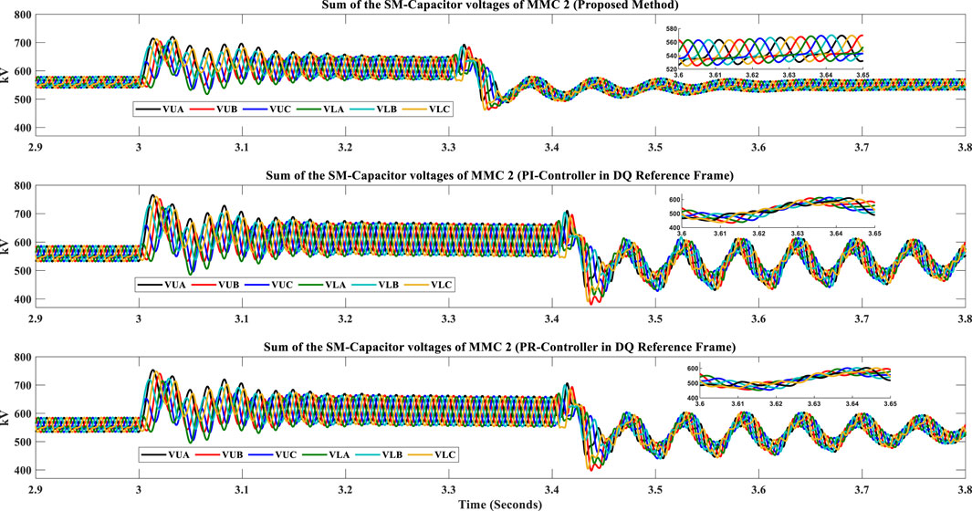
FIGURE 9. Sum of the SM-Capacitor voltages of MMC 2: (A) proposed controller (B) PI controller (C) PR controller.
5.2 Simulation results for scenario 2 at AC grid 1 connected to MMC 1
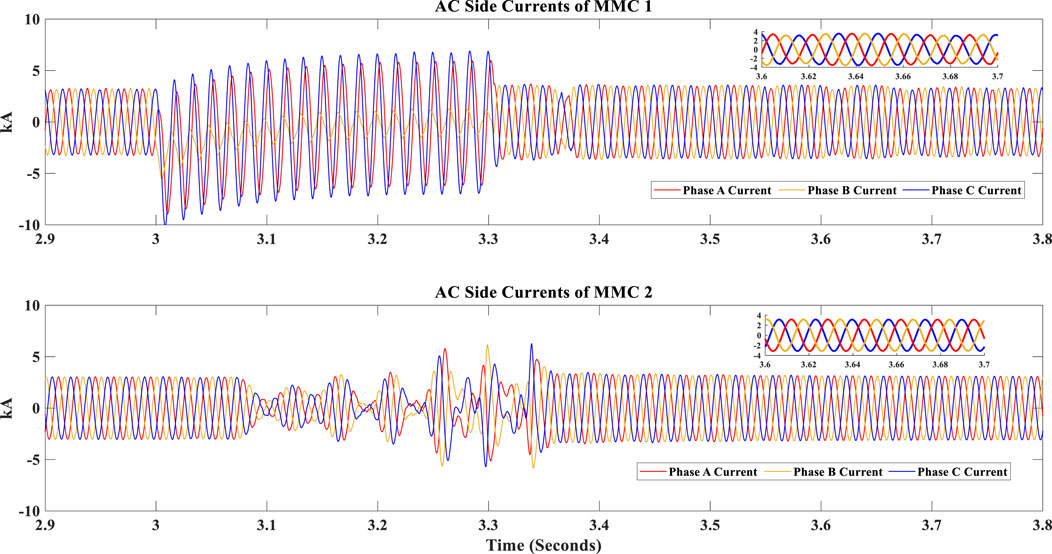
As already discussed in scenario 1, it is assumed that the direction of the positive power flow is from MMC 1 to MMC 2. To examine the robustness of the proposed HVDC system, an SLG fault has been applied at AC Grid 1 in this section. The lack of power in the DC link causes DC under-voltage when a failure in grid 1 occurs and the power flow direction prior to the fault is positive. In a HVDC system, a SLG fault causes a voltage sag on the ac side MMC, which immediately reduces the MMC’s power capacity, as shown in Figure 10B. The proposed FRT approach must be used to coordinate two MMC terminals in order to protect the MMCs from SM capacitor overvoltage and power imbalance in the event of an SLG fault. In order to ensure the stability of the power system during the FRT, the system is predicted to closely match the prefault active power. Results from the simulation for the DC link voltages at MMC 1 and MMC 2 stations are shown in Figure 10A. Power and DC link voltages at both MMC stations have negligible deviations from reference value after the fault is cleared, as shown in Figure 10 Phase A voltages (connected to MMC 1) reaches to zero during the fault period, as shown in Figure 10C. This results into slight increase in AC side currents of MMC 1, as shown in Figure 11A. However, phase voltages (connected to MMC 2) goes through negligible disturbance during this fault, as shown in Figure 10D. It can be observed from Figure 11B that AC side currents of MMC 1 and MMC 2 fluctuates within permissible limits during the fault and as soon as fault is cleared, the currents reach their desired value. Phase voltages and AC side currents of both MMC stations are purely sinusoidal (having reduced THD) following standard grid codes as shown in zoomed-in portion of Figures 9, 10
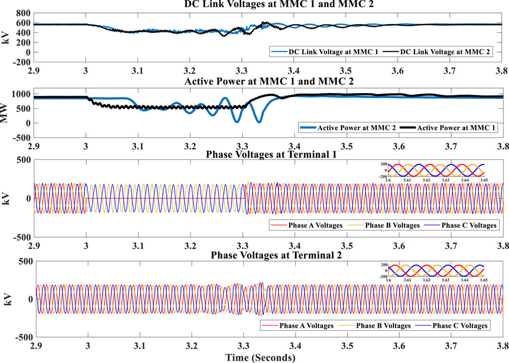
FIGURE 10. (A) DC Link Voltages at MMC 1 and MMC 2 (B) Active Power at MMC 1 and MMC 2 (C) Phase Voltages connected to MMC 1 (D) Phase Voltages connected to MMC2.
Compared to Scenario 1, addressing CVR and CC reduction becomes even more challenging in the case of an unbalanced grid (SLG fault). It is worth noting that arm capacitors are typically designed to withstand twice the rated DC voltage (Prieto-Araujo et al, 2017). In Scenario 2, similar to Scenario 1, the proposed controller outperforms conventional PI and PR-based CC suppression methods, demonstrating a faster dynamic response and reduced steady-state error, as illustrated in Figure 12. The controller effectively suppresses the second harmonic current, decreasing converter losses and reducing current stresses on switches. It also tackles the CVR issue, ensuring balanced capacitor voltages and maintaining safe operational limits throughout the fault, as depicted in Figure 13A. In contrast, PI and PR-based methods mainly concentrate on reducing CC, resulting in higher ripple magnitudes and unbalanced capacitor voltages, as shown in Figures 13B, C, respectively. Consequently, the proposed method excels in circulating current control and capacitor voltage regulation compared to PI and PR controllers. The superiority of the proposed controller over the PI and PR controllers is summarized in Table 2.
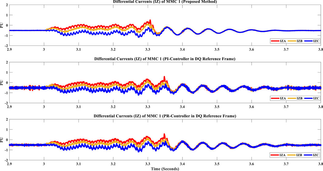
FIGURE 12. Differential Currents of MMC 1: (A) proposed controller (B) PI controller (C) PR controller.
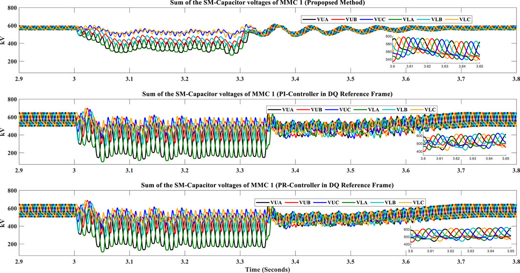
FIGURE 13. Sum of the SM-Capacitor voltages of MMC 1: (A) proposed controller (B) PI controller (C) PR controller.
From the above detailed discussions, it is clear that the proposed communication-free AC FRT scheme ensures comprehensive FRT capability without the need for additional expensive DC choppers. Moreover, the optimized CC suppression method properly manages the CC and CVR within allowable limits. The system ensures quick post fault recovery operation and exhibits reduced oscillations (THD).
6 Conclusion
This research paper has presented a comprehensive analysis of the reliability and stability of MMC-based HVDC systems, addressing significant challenges such as FRT, CC suppression, and CVR reduction. The proposed communication-free FRT strategy developed in this study effectively guarantees stable operation during both balanced and unbalanced AC faults, eliminating the need for an additional DC chopper. The proposed CC control strategy proficiently reduces the CC magnitude to less than 10% of the nominal current, meeting grid code requirements. A comparative analysis between the proposed CC controller and traditional PI and PR-based controllers highlights the superiority of the proposed method. The dynamic response time of the proposed controller achieves a steady state at nearly 3.6 s (within 0.3 s after the fault disappears), while the PI and PR controllers reach a steady state at approximately 3.7 s (within 0.4 s after the fault disappears). This indicates a faster response in circulating current control for the proposed controller. Moreover, the proposed CC controller ensures efficient second harmonic current suppression, an area in which the PI and PR controllers are inadequate. Lastly, the proposed method effectively addresses CVR, ensuring that capacitor voltages remain within safe limits during rapid post-fault recovery operations. The results of this thorough investigation underscore the potential of the proposed strategies in enhancing the performance and resilience of MMC-based HVDC systems, paving the way for more dependable and efficient power transmission in future grid networks.
Data availability statement
The original contributions presented in the study are included in the article/supplementary material, further inquiries can be directed to the corresponding author.
Author contributions
All authors listed have made a substantial, direct, and intellectual contribution to the work and approved it for publication.
Acknowledgments
This work was supported by the Researchers Supporting Project number (RSPD 2023R646), King Saud University, Riyadh, Saudi Arabia.
Conflict of interest
The authors declare that the research was conducted in the absence of any commercial or financial relationships that could be construed as a potential conflict of interest.
Publisher’s note
All claims expressed in this article are solely those of the authors and do not necessarily represent those of their affiliated organizations, or those of the publisher, the editors and the reviewers. Any product that may be evaluated in this article, or claim that may be made by its manufacturer, is not guaranteed or endorsed by the publisher.
References
Adam, G. P., AhmedFinney, K. H. S. J., and Williams, B. W. (2010). “AC fault ride-through capability of a VSC-HVDC transmission systems,” in 2010 IEEE Energy Conversion Congress and Exposition, Atlanta, United States, September 2010, 3739–3745.
Ali, S., Soomro, J. B., Mughal, M., Chachar, F. A., Bukhari, S. S. H., and Ro, J. S. (2020). Power quality improvement in HVDC MMC with modified nearest level control in real-time HIL based setup. IEEE Access 8, 221712–221719. doi:10.1109/access.2020.3043811
Ansari, J. A., Liu, C., and Zheng, L. (2022). “An enhanced fault ride-through capability for MTDC systems using vector current control and inherent energy of submodules of MMC,” in 2022 9th International Conference on Electrical and Electronics Engineering (ICEEE), Alanya, Turkey, March 2022 (IEEE), 190–197.
Chandio, R. H., Chachar, F. A., Soomro, J. B., Ansari, J. A., Munir, H. M., Zawbaa, H. M., et al. (2023). Control and protection of MMC-based HVDC systems: A review. Energy Rep. 9 (2023), 1571–1588. doi:10.1016/j.egyr.2022.12.056
Cheng, F., Yao, L., Xu, J., Chi, Y., Sun, Y., Wang, Z., et al. (2021). A comprehensive AC fault ride-through strategy for HVDC link with serial-connected LCC-VSC hybrid inverter. CSEE J. Power Energy Syst. 8 (1), 175–187. doi:10.17775/CSEEJPES.2020.03510
Cui, S., Kim, S., Jung, J.-J., and Sul, S.-K. (2014). “A comprehensive cell capacitor energy control strategy of a modular multilevel converter (MMC) without a stiff DC bus voltage source,” in 2014 IEEE Applied Power Electronics Conference and Exposition-APEC 2014, Texas, United States, March 2014, 602–609.
Cui, S., Lee, H.-J., Jung, J.-J., Lee, Y., and Sul, S.-K. (2015). “A comprehensive AC side single line to ground fault ride through strategy of a modular multilevel converter for HVDC system,” in 2015 IEEE Energy Conversion Congress and Exposition (ECCE), Montreal, Canada, September 20 – 24, 2015, 5378–5385.
Cui, S., Lee, H.-J., Jung, J.-J., Lee, Y., and Sul, S.-K. (2018). A comprehensive AC-side single-line-to-ground fault ride through strategy of an MMC-based HVDC system. IEEE J. Emerg. Sel. Top. Power Electron. 6 (3), 1021–1031. doi:10.1109/jestpe.2018.2797934
Daoud, M. I., Massoud, A. M., Abdel-Khalik, A. S., Ahmed, E., and Ahmed, S. (2015). A flywheel energy storage system for fault ride through support of grid-connected VSC HVDC-based offshore wind farms. IEEE Trans. Power Syst. 31 (3), 1671–1680. doi:10.1109/tpwrs.2015.2465163
Erlich, I., Feltes, C., and Shewarega, F. (2013). Enhanced voltage drop control by VSC–HVDC systems for improving wind farm fault ridethrough capability. IEEE Trans. Power Deliv. 29 (1), 378–385. doi:10.1109/tpwrd.2013.2285236
Gomis-Bellmunt, O., Sau Bassols, J., Prieto-Araujo, E., and Cheah-Mane, M. (2019). Flexible converters for meshed HVDC grids: From flexible AC transmission systems (FACTS) to flexible DC grids. IEEE Trans. Power Deliv. 35 (1), 2–15. doi:10.1109/tpwrd.2019.2939588
Hafeez, K., Khan, S. A., Alex Van den Bossche, , and Kamel Djamel Eddinne, (2020). Capacitor energy variations in MMC using harmonics injection. Power Electron. Drives 5, 97–107. doi:10.2478/pead-2020-0007
Hafeez, K., Khan, S. A., Alex Van Den Bossche, , and Ul Hasan, Q. (2021). Capacitor voltage ripple reduction in MMC-HVDC system using flat bottom current method. Electr. Eng. 103 (3), 1483–1492. doi:10.1007/s00202-020-01169-2
Hoehn, T., Slettbakk, T., Blanquez, F., Kahle, K., and Burnet, J. P. (2019). “Back-to-Back HVDC modular multilevel converter for transient voltage dip mitigation in passive networks,” in 2019 21st European Conference on Power Electronics and Applications (EPE'19 ECCE Europe), Genova, Italy, September 2019 (IEEE), 1.
Ilves, K., Antonopoulos, A., Harnefors, L., Norrga, S., Ängquist, L., and Nee, H.-P. (2011). “Capacitor voltage ripple shaping in modular multilevel converters allowing for operating region extension,” in In IECON 2011-37th Annual Conference of the IEEE Industrial Electronics Society, Victoria, Australia, November 2011, 4403–4408.
Ishfaq, M., Uddin, W., Zeb, K., Khan, I., Ul Islam, S., Khan, M. A., et al. (2019). A new adaptive approach to control circulating and output current of modular multilevel converter. Energies 12 (6), 1118. doi:10.3390/en12061118
Isik, S., Alharbi, M., and Bhattacharya, S. (2021). An optimized circulating current control method based on PR and PI controller for MMC applications. IEEE Trans. Industry Appl. 57 (5), 5074–5085. doi:10.1109/tia.2021.3092298
Isik, S., Alharbi, M., and Bhattacharya, S. (2020). “Optimized circulating current control method based on proportional resonant and proportional integral controllers for modular multi-level converter applications,” in 2020 IEEE Energy Conversion Congress and Exposition (ECCE), Detroit, Michigan, October 2020, 5709–5715.
Jiang, Y., Shu, H., and Liao, M. (2023). Fault-tolerant control strategy for sub-modules open-circuit fault of modular multilevel converter. Electronics 12 (5), 1080. doi:10.3390/electronics12051080
Khan, S. A., Ansari, J. A., Chandio, R. H., Munir, H. M., Alharbi, M., and Alkuhayli, A. (2022). AI based controller optimization for VSC-MTDC grids. Front. Energy Res. 10. doi:10.3389/fenrg.2022.1008099
Kirakosyan, A., El Moursi, M. S., and Khadkikar, V. (2016). Fault ride through and grid support topology for the VSC-HVDC connected offshore wind farms. IEEE Trans. Power Deliv. 32 (3), 1592–1604. doi:10.1109/tpwrd.2016.2624503
Li, J., Konstantinou, G., Wickramasinghe, H. R., Townsend, C. D., and Pou, J. (2019). Capacitor voltage reduction in modular multilevel converters under grid voltages unbalances. IEEE Trans. Power Deliv. 35 (1), 160–170. doi:10.1109/tpwrd.2019.2919788
Li, W., Zhu, M., Chao, P., Liang, X., and Xu, D. (2019). Enhanced FRT and postfault recovery control for MMC-HVDC connected offshore wind farms. IEEE Trans. Power Syst. 35 (2), 1606–1617. doi:10.1109/tpwrs.2019.2944940
Luscan, B., Bacha, S., Benchaib, A., Bertinato, A., Chédot, L., Gonzalez-Torres, J. C., et al. (2020). A vision of HVDC key role toward fault-tolerant and stable AC/DC grids. IEEE J. Emerg. Sel. Top. Power Electron. 9 (6), 7471–7485. doi:10.1109/jestpe.2020.3037016
Malanda, S. C. (2020). “Innocent E. Davidson, and grain A. Adam. "Comparison of DC voltage control strategies for multi-terminal HVDC network during AC faults,” in 2020 International SAUPEC/RobMech/PRASA Conference, Cape Town, South Africa, January 2020, 1–6.
Naderi, S. B., Negnevitsky, M., and Muttaqi, K. M. (2018). A modified DC chopper for limiting the fault current and controlling the DC-link voltage to enhance fault ride-through capability of doubly-fed induction-generator-based wind turbine. IEEE Trans. Industry Appl. 55 (2), 2021–2032. doi:10.1109/tia.2018.2877400
Nakajima, T., and Irokawa, S. (1999). “A control system for HVDC transmission by voltage sourced converters,” in 1999 IEEE Power Engineering Society Summer Meeting. Conference Proceedings (Cat. No. 99CH36364), Edmonton, Canada, July 1999, 1113–1119.
Oguma, K., and Akagi, H. (2016). Low-voltage-ride-through (LVRT) control of an HVDC transmission system using two modular multilevel DSCC converters. IEEE Trans. Power Electron. 32 (8), 5931–5942. doi:10.1109/tpel.2016.2615048
Pannell, G., Zahawi, B., Atkinson, D. J., and Missailidis, P. (2013). Evaluation of the performance of a DC-link brake chopper as a DFIG low-voltage fault-ride-through device. IEEE Trans. energy Convers. 28 (3), 535–542. doi:10.1109/tec.2013.2261301
Pou, J., Ceballos, S., Konstantinou, G., Agelidis, V. G., Picas, R., and Zaragoza, J. (2014). Circulating current injection methods based on instantaneous information for the modular multilevel converter. IEEE Trans. Industrial Electron. 62 (2), 777–788. doi:10.1109/tie.2014.2336608
Prieto-Araujo, E., Junyent-Ferré, A., Collados-Rodríguez, C., Clariana-Colet, G., and Gomis-Bellmunt, O. (2017). Control design of Modular Multilevel Converters in normal and AC fault conditions for HVDC grids. Electr. Power Syst. Res. 152, 424–437. doi:10.1016/j.epsr.2017.06.020
Qi, L., Wu, S., Zhang, X., Zhang, M., Liu, C., Wang, H., et al. (2021). A low-cost DC chopper with coupling transformer for offshore wind VSC-HVdc system. IEEE Trans. Power Electron. 37 (5), 4979–4984. doi:10.1109/tpel.2021.3135286
Ramtharan, G., Arulampalam, A., Janaka Bandara Ekanayake, , Hughes, F. M., and Jenkins, N. (2009). Fault ride through of fully rated converter wind turbines with AC and DC transmission systems. IET Renew. Power Gener. 3 (4), 426–438. doi:10.1049/iet-rpg.2008.0018
Shah, R., Islam, S., and Islam, Md R. (2020). “Impact of MMC-HVDC control parameter selection on the dynamic performance of AC system,” in 2020 IEEE International Conference on Applied Superconductivity and Electromagnetic Devices (ASEMD), Tianjin, China, October 2020, 1–2.
Silva, B., Leal Moreira, C., Leite, H., and Lopes, J. A. P. (2014). Control strategies for AC fault ride through in multiterminal HVDC grids. IEEE Trans. Power Deliv. 29 (1), 395–405. doi:10.1109/tpwrd.2013.2281331
Slettbakk, T. E. (2018). “Development of a power quality conditioning system for particle accelerators,”. PhD diss (Trondheim Ålesund Gjøvik , Norway: Norwegian U. Sci. Tech).
Soomro, J. B., Akhter, F., Ali, S., Bukhari, S. S. H., Sami, I., and Ro, J. S. (2021). Modified nearest level modulation for full-bridge based HVDC MMC in real-time hardware-in-loop setup. IEEE Access 9 (2021), 114998–115005. doi:10.1109/access.2021.3105690
Soomro, J. B., Akhtar, F., Hussain, R., Ahmed Ansari, J., and Munir, H. M. (2022). A detailed review of MMC circuit topologies and modelling issues. Int. Trans. Electr. Energy Syst. 2022, 1–17. doi:10.1155/2022/8734010
Tavakoli, S. D., Prieto-Araujo, E., and Gomis-Bellmunt, O. (2021). AC fault ride through in MMC-based HVDC systems. IEEE Trans. Power Deliv. 37, 2775–2786. doi:10.1109/tpwrd.2021.3116508
Tzelepis, D., Oulis Rousis, A., Dyśko, A., Booth, C., and Strbac, G. (2017). A new fault-ride-through strategy for MTDC networks incorporating wind farms and modular multi-level converters. Int. J. Electr. Power and Energy Syst. 92, 104–113. doi:10.1016/j.ijepes.2017.04.015
Ud Din, W., Zeb, K., Ishfaq, M., Ul Islam, S., Khan, I., and Kim, H. J. (2019). Control of internal dynamics of grid-connected modular multilevel converter using an integral backstepping controller. Electronics 8 (4), 456. doi:10.3390/electronics8040456
Uddin, W., TiagoBusarello, D. C., Zeb, K., Khan, M. A., Kumar Yedluri, A., and Kim, H.-J. (2021). Control strategy based on arm-level control for output and circulating current of MMC in stationary reference frame. Energies 14, 4160. doi:10.3390/en14144160
Uddin, W., Zeb, K., Adil Khan, M., Ishfaq, M., Khan, I., Islam, S. U., et al. (2019). Control of output and circulating current of modular multilevel converter using a sliding mode approach. Energies 12 (21), 4084. doi:10.3390/en12214084
Wang, H., Wang, Y., Duan, G., Hu, W., Wang, W., and Chen, Z. (2017). An improved droop control method for multi-terminal VSC-HVDC converter stations. Energies 10 (7), 843. doi:10.3390/en10070843
Wang, S., Bao, D., Gontijo, G., Chaudhary, S., and Teodorescu, R. (2021). Modeling and mitigation control of the submodule-capacitor voltage ripple of a modular multilevel converter under unbalanced grid conditions. Energies 14 (3), 651. doi:10.3390/en14030651
Wang, S., Dragicevic, T., Gao, Y., and Teodorescu, R. (2020). Neural network based model predictive controllers for modular multilevel converters. IEEE Trans. Energy Convers. 36 (2), 1562–1571. doi:10.1109/tec.2020.3021022
Wang, S., Dragicevic, T., Gontijo, G. F., Sanjay, K., and Teodorescu, R. (2020). Machine learning emulation of model predictive control for modular multilevel converters. IEEE Trans. Industrial Electron. 68 (11), 11628–11634. doi:10.1109/tie.2020.3038064
Wang, S., Dragicevic, T., and Teodorescu, R. (2020). “Learning based capacitor voltage ripple reduction of modular multilevel converters under unbalanced grid conditions with different power factors,” in 2020 IEEE 11th International Symposium on Power Electronics for Distributed Generation Systems (PEDG), Dubrovnik, Croatia, September 2020, 531–535.
Wang, S., Teodorescu, R., and Chaudhary, S. K. (2018). “Capacitor voltage ripple reduction methods of modular multilevel converter under unbalanced fault conditions: A comparison,” in 2018 IEEE International Power Electronics and Application Conference and Exposition (PEAC), Shenzhen, China, November 4-7, 2018, 1–6.
Wang, W., Antony, B., Barnes, M., and Marjanovic, O. (2014). Analysis of active power control for VSC–HVDC. IEEE Trans. Power Deliv. 29 (4), 1978–1988. doi:10.1109/tpwrd.2014.2322498
Wang, X., Zou, J., Zhao, J., Xie, C., Li, K., Munir, H. M., et al. (2018). A novel model predictive control strategy to eliminate zero-sequence circulating current in paralleled three-level inverters. IEEE J. Emerg. Sel. Top. Power Electron. 7 (1), 309–320. doi:10.1109/jestpe.2018.2879645
Wang, Y., Shi, X., Chen, M., Jing, L., Li, X., Zhang, Z., et al. (2023). Peak arm current minimization of modular multilevel converter using multiple circulating current injection. Electronics 12, 1695. doi:10.3390/electronics12071695
Wu, S., Zhang, X., Jia, W., Zhu, Y., Qi, L., Guo, X., et al. (2021). A modular multilevel converter with integrated energy dissipation equipment for offshore wind VSC-HVDC system. IEEE Trans. Sustain. Energy 13 (1), 353–362. doi:10.1109/tste.2021.3111751
Xin, Y., Lou, W., Li, G., Jiang, S., Wang, T., and Yang, Y. (2021). AC fault ride-through coordinated control strategy of LCC-MMC hybrid DC transmission system connected to passive networks. Int. J. Electr. Power and Energy Syst. 131, 107076. doi:10.1016/j.ijepes.2021.107076
Xu, B., Gao, C., Zhang, J., Yang, J., Xia, B., and He, Z. (2020). A novel DC chopper topology for VSC-based offshore wind farm connection. IEEE Trans. Power Electron. 36 (3), 3017–3027. doi:10.1109/tpel.2020.3015979
Xu, C., Zhang, X., Yu, Z., Zhao, B., Chen, Z., and Zeng, R. (2019). A novel DC chopper with MOV-based modular solid-state switch and concentrated dissipation resistor for±400 kV/1100 MW offshore wind VSC-HVDC system. IEEE Trans. Power Electron. 35 (5), 4483–4488. doi:10.1109/tpel.2019.2950706
Yang, L., Zhao, X., Jacob, O., ZhaoDong, Y., and Wong, K. P. (2011). Advanced control strategy of DFIG wind turbines for power system fault ride through. IEEE Trans. power Syst. 27 (2), 713–722. doi:10.1109/tpwrs.2011.2174387
Keywords: HVDC, fault ride-through (FRT), modular multilevel converter (MMC), circulating current control circuit, stability
Citation: Badar J, Akhtar F, Kumar D, Munir HM, Ali KH, Alsaif F and Alsulamy S (2023) An MMC based HVDC system with optimized AC fault ride-through capability and enhanced circulating current suppression control. Front. Energy Res. 11:1190975. doi: 10.3389/fenrg.2023.1190975
Received: 22 March 2023; Accepted: 16 May 2023;
Published: 24 May 2023.
Edited by:
Ningyi Dai, University of Macau, ChinaReviewed by:
Daniel Fodorean, Technical University of Cluj-Napoca, RomaniaJianhang Zhu, The University of Hong Kong, Hong Kong SAR, China
Copyright © 2023 Badar, Akhtar, Kumar, Munir, Ali, Alsaif and Alsulamy. This is an open-access article distributed under the terms of the Creative Commons Attribution License (CC BY). The use, distribution or reproduction in other forums is permitted, provided the original author(s) and the copyright owner(s) are credited and that the original publication in this journal is cited, in accordance with accepted academic practice. No use, distribution or reproduction is permitted which does not comply with these terms.
*Correspondence: Faisal Alsaif, RmFhbHNhaWZAa3N1LmVkdS5zYQ==
 Jahangeer Badar
 Faheem Akhtar1
 Dileep Kumar
 Hafiz Mudassir Munir
 Faisal Alsaif