 Lin Zhu
 Leke Chen1
 Min Xu
95% of researchers rate our articles as excellent or good
Learn more about the work of our research integrity team to safeguard the quality of each article we publish.
Find out more
ORIGINAL RESEARCH article
Front. Energy Res. , 23 May 2023
Sec. Process and Energy Systems Engineering
Volume 11 - 2023 | https://doi.org/10.3389/fenrg.2023.1184119
This article is part of the Research Topic Advanced Technologies of Integrated Energy System for Carbon Neutrality View all 7 articles
Grid-connected permanent magnet synchronous generator (PMSG) wind farms may be susceptible to oscillation when connected to weak grids. This paper explores the root causes of the oscillations from two perspectives: the model and the oscillation frequency band. First, the small signal model of PMSG wind farm grid-side system is established, and the small disturbance comparison with the PMSGA full-order electromagnetic transient model in MATLAB/Simulink is carried out. Then, we calculatue the eigenvalues of the small signal model and use model analysis techniques such as participation factors calculation and root locus method to identify the critical factors that cause the oscillation modes to be dominant. Finally, time-domain simulation is used to verify the theoretical analysis. Two dominant modes are identified: the subsynchronous oscillation mode and the low-frequency oscillation mode. The subsynchronous oscillation mode is closely related to the direct current (DC) voltage control and the dynamics of DC link. The low-frequency oscillation is significantly weakened with the decrease in grid strength, and it is closely related to the phase-locked loop (PLL) control. The conclusions can provide a reference for tuning the control parameters of PMSG converter.
The rapid development of renewable energy grid-connected power generation technology, represented explicitly by wind power, has played a crucial role in addressing the energy crisis. We believe that integrating renewable energy can significantly contribute to achieving the goal of carbon neutrality. Direct-drive permanent magnet synchronous generators (PMSGs) are widely used because of their high efficiency and low failure rate. However, there is a risk of oscillations in wind farms with weak grid interconnections, which poses a severe threat to the safe and stable operation of the power system (Strachan and Jovcic, 2010; Fan and Miao, 2018). Consequently, further study of the oscillation problem caused by PMSG connected to the power grid is imperative.
In traditional power systems, oscillations can be classified into local mode and global mode according to the different forms and mechanisms of oscillations (Kundur, 1994). Similarly, PMSG oscillations can be broadly categorized into two situations based on reported incidents: subsynchronous oscillations and low-frequency oscillations. For example, a PMSG wind farm in Xinjiang, China, experienced a subsynchronous oscillation accident in 2015 due to the low short-circuit ratio (SCR) of the point of common coupling (PCC) (Xie et al., 2016). In the low-frequency range, an accident occurred in Texas, United States, in 2011 with an oscillation frequency of 4 Hz, which is slightly higher than the low-frequency oscillations of the traditional power system (Fan and Miao, 2018; Li et al., 2020b; Cheng et al., 2023). The problem of PMSG grid-connected oscillation has caught the attention of many researchers.
Various analysis methods have been employed, among which the most common ones are impedance analysis and eigenvalue analysis. These methods are widely recognized for their effectiveness in shedding light on the underlying causes of the oscillation problem and identifying potential solutions (Li et al., 2020a; Xu et al., 2020; Liu et al., 2021; Shao et al., 2021; Xu et al., 2021; Liu et al., 2022).
As one of the powerful tools for oscillation analysis, the impedance analysis method establishes the transfer function of each link of the system and integrates them to obtain the impedance model of the whole system, and then combines with the impedance stability criterion to analyze the stability of the impedance model (Li et al., 2020a; Xu et al., 2021). (Li et al., 2020a) established the dq impedance model of the grid-connected inverter and analyzed the impact of grid impedance and inner current loop on the stability of the system. (Xu et al., 2021) established the single-input single-output transfer function of the PMSG grid-connected system, which can be combined with the generalized Nyquist stability criterion and the eigenvalue sensitivity matrix to analyze the relevant influencing factors of the oscillation. While the impedance analysis method is a practical approach, it may be limited in its ability to analyze the internal interaction between two dynamic components within the system and explain the coupling mechanism of the oscillation mode between the internal states (Liu et al., 2021).
In order to study the complex mechanism of PMSG grid-connected oscillation in-depth, many scholars have adopted the eigenvalue analysis method to calculate the primary information of each oscillation mode of the system, including the participation factors related to each eigenvalue (Shao et al., 2021). Considering the control loops such as the active power outer loop, current inner loop, and Phase Locked Loop (PLL), (Xu et al., 2020) established a state-space model of voltage source converter and analyzed the model eigenvalues. (Liu et al., 2022) ignored the dynamics of the PMSG machine side system because the converters on both sides of the PMSG grid-connected system are separated by the DC link, taking into account the effects of the control delay when establishing the grid-side system state space model of PMSG. However, building a state-space model for a large-scale system will face the curse of dimensionality. The above literature uses a simplified reduced-order inverter model to replace the PMSG grid-connected system to avoid this problem and does not compare the performance difference between the research model and the full-order detailed model.
In fact, many scholars simplified the research model in different details, leading to different conclusions on the attribution of the oscillations of grid-connected PMSG systems (Xu and Cao, 2018; Xiao and Xu, 2022; Wang et al., 2023). (Wang et al., 2023) pointed out that the negative impedance introduced by PLL, the negative impedance, and the capacitive impedance introduced by grid voltage feed-forward are the critical factors of system instability. (Xu and Cao, 2018) found that subsynchronous oscillation is closely related to PLL parameters, current inner loop parameters, and grid strength, but the study model ignored the influence of outer voltage control. Meanwhile, after analyzing the impact of outer voltage control and phase-locked loop parameters on stability, (Xiao and Xu, 2022) found that the improper setting of voltage outer loop parameters is the most critical factor for the instability of the system. The above work is of value, but there are still evident differences in the oscillation influencing factors. Unfortunately, the above studies have not reached a consensus on the mechanism of oscillations.
On the other hand, using the idea of classification discussion to divide the oscillations induced by PMSG into two categories according to the frequency band is an effective means to make the analysis of oscillation causes more accurate. A recent study (Li et al., 2020b) investigated the influencing factors of low-frequency oscillation and subsynchronous oscillation in PMSG. Their findings suggest that different PLL bandwidths may be the possible cause of different types of oscillations and that the influencing factors of both types of oscillations change with the alteration of PLL bandwidth. However, their analysis did not delve into the impact of other factors on oscillation. To address this gap, we propose to take a two-pronged approach, focusing on the model and oscillation frequency band. Specifically, we will first analyze the performance of the established model in terms of small disturbance stability and then use this model to investigate the influencing factors that induce oscillations in different frequency bands.
This paper aims to make a significant contribution to the analysis of PMSG grid-connected systems in various grid conditions by comparing the performance of the grid-side small signal model and the full-order electromagnetic transient model in terms of small-disturbance stability. By analyzing the eigenvalues of the small signal model, two distinct types of oscillation modes are identified: subsynchronous oscillation mode and low-frequency oscillation mode. The study also investigates the critical factors that cause the oscillation modes to be dominant, revealing that subsynchronous oscillation is related to DC voltage control. In contrast, low-frequency oscillation is closely related to PLL control and is more sensitive to changes in grid strength. The proposed findings are rigorously tested and verified using a MATLAB/Simulink-based test platform.
The rest of this paper is structured as follows: Section 2 establishes the small signal model of the grid-side system of the PMSG grid-connected wind farm. Section 3 compares the time-domain responses from the small signal model of the grid-side system and the detailed electromagnetic transient model of MATLAB/Simulink. We analyze the eigenvalues of the PMSG grid-connected system and compare the calculation results of the oscillation frequency with the waveform spectrum analysis obtained from the time-domain simulation to verify the accuracy of the small signal modeling. Section 4 gives the critical influencing factors of the dominant two oscillation modes and conducts time-domain simulation verification. Section 5 concludes the paper.
A complete PMSG wind turbine includes synchronous generator (SG) dynamics, machine-side converter (MSC), DC link dynamics, grid-side converter (GSC), PLLs, etc., (Bao et al., 2022). A single PMSG grid-connected structure is shown in Figure 1.
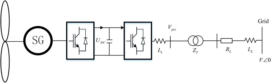
FIGURE 1. Basic structure diagram of a PMSG.
The following subsections will introduce the dynamic model, including DC link, GSC vector control, PLL, and AC grid. In the dynamic model, there are the DQ synchronous reference frame for power flow calculation and the dq reference frame for converters. The former has its D-axis aligned with the grid voltage space vector, while the latter has its d-axis aligned with the PCC voltage space vector. The relationship between the two coordinate systems is shown in Figure 2.
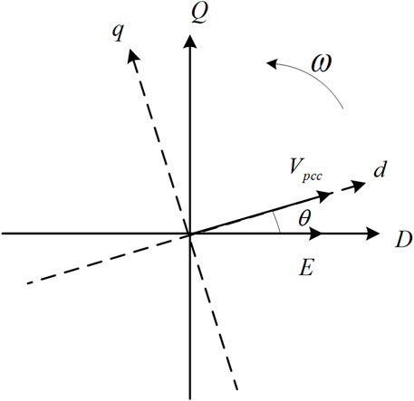
FIGURE 2. Relationship of the dq reference frame and the DQ reference frame.
The power flowing through the DC capacitor is
When the machine-side dynamics are ignored, it is assumed that the MSC rectifies to obtain a constant DC current
Also, under the condition of ignoring the line and converter loss, when the reactive power output of the GSC is close to 0, the active power delivered by the DC capacitor to the GSC is equal to the active power of the GSC at PCC:
where
The grid-side converter employs a double closed-loop control structure. The d-axis outer loop adopts constant DC voltage control, and the q-axis outer loop adopts constant AC voltage and reactive power control. The block diagram of the GSC control is shown in Figure 3.
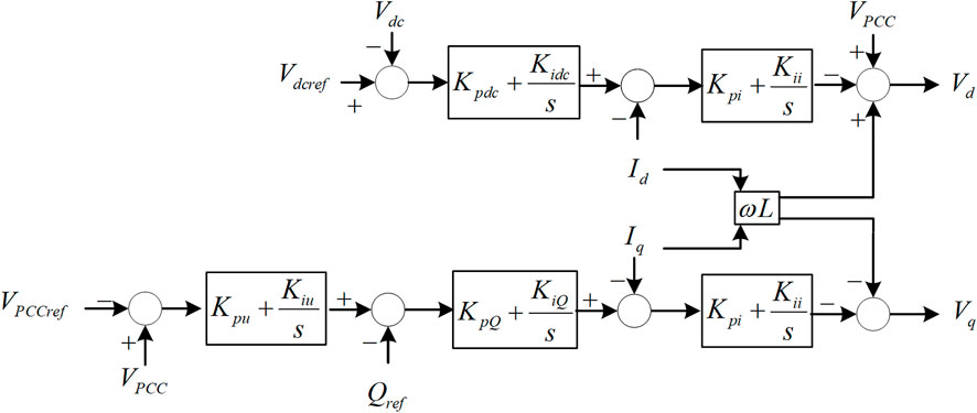
FIGURE 3. Block diagram for the GSC control.
Its governing equations are:
where the reactive power output of the GSC
The PLL takes the PCC voltage as the input and outputs the phase, frequency, and amplitude of the PCC voltage, which is the key to synchronizing the converter with the grid. Take the direction of the PCC voltage as the d-axis direction of the dq reference frame of the converter. The block diagram of the PLL used in this paper is shown in Figure 4:
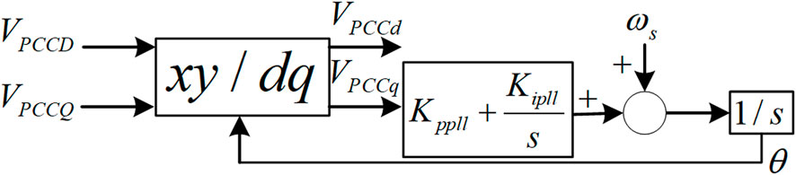
FIGURE 4. Block diagram of PLL.
The PLL dynamics are as follows:
where
The mathematical model of the Grid-side filter inductance is as follow:
where
As can be seen from Figure 1, the impedance is connected in series between the grid-side converter and the infinite bus representing the ideal AC grid in the paper, and different short-circuit ratios are set by adjusting the impedance. The mathematical model of the grid is:
where
Combined with the mathematical models of the DC link, GSC vector control, PLL, filter, AC grid, etc., the state space equation set of the PMSG grid-connected wind farm system is obtained. The state space equation is linearized at the steady-state operating point to obtain the entire small signal model of the system, which is shown as:
where
To verify the accuracy of the developed small signal model effectively, we build a detailed electromagnetic transient simulation model of the PMSG grid-connected wind farm in MATLAB/Simulink, including the machine-side and grid-side systems. The accuracy of the linearized small signal model is assessed by comparing the time-domain responses obtained from the small signal model, which retains only the grid-side system, with the detailed electromagnetic transient simulation. The circuit and control parameters of the PMSG grid-connected wind power system are listed in Table 1.
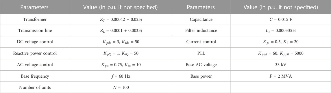
TABLE 1. Circuit and control parameters of PMSG grid-connected wind power system.
Initially, the system operates at the nominal operating point (the reference of the DC link voltage
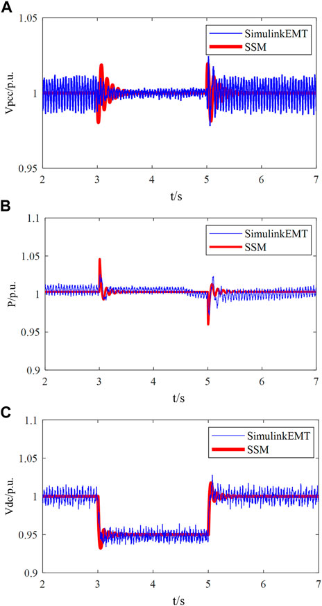
FIGURE 5. Time-domain responses under step-change of
The results presented in Figure 5 show that the overall system exhibits satisfactory dynamic behavior when controlled using the parameters outlined in Table 1. In addition, the close agreement between the dynamic responses obtained from the small signal model and the detailed EMT simulations provides compelling evidence of the nearly identical performance. This validation strengthens confidence in the accuracy and reliability of both models.
Based on the small signal model of the PMSG grid-connected system, this subsection calculates the system eigenvalues under different grid strengths. Then it analyses the oscillation frequency and the damping ratio of the oscillation modes. Meanwhile, under the same grid-connected conditions, the spectrum analysis of the current waveform of the Simulink time-domain simulation is performed, and the correctness of the eigenvalue calculation is verified by comparing the oscillation frequencies of the oscillation modes with the spectrum analysis results.
The grid strength of the power system can be expressed by short-circuit ratio (SCR). The SCR of the grid-connected wind farm system is the ratio of the AC grid short-circuit capacity to the wind farm capacity. The grid strength increases with the increase of SCR. Grid strength will not only affect the steady-state operating point of the power system but also affect the recovery ability of the power system after a disturbance. The calculation formula of the short-circuit ratio of the grid-connected system of the wind farm is:
where
Adjust the line impedance
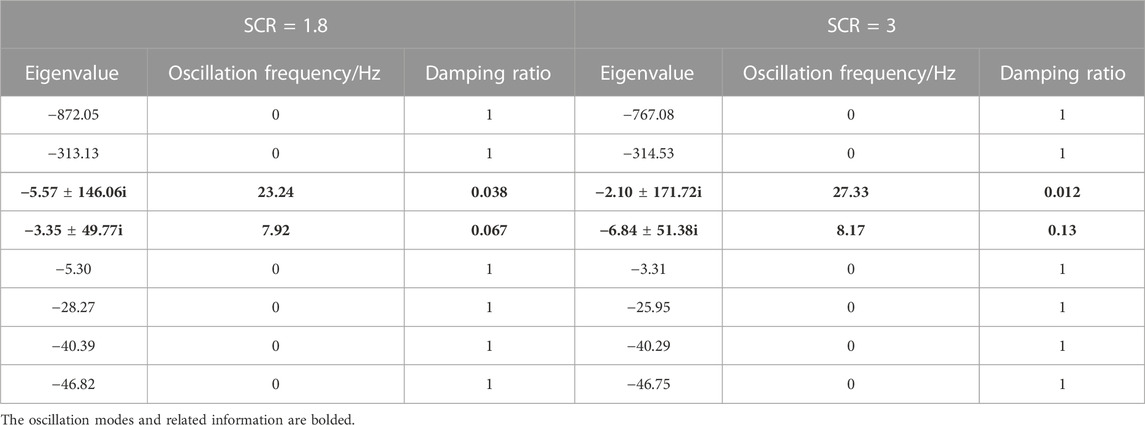
TABLE 2. Eigenvalue calculation results under different SCR.
It can be seen from Table 2 that when the system parameters of the PMSG grid-connected wind farm are set as shown in Table 1, the small signal system has two oscillation modes under both SCR conditions. The oscillation frequencies of the first oscillation mode (Mode 1) are 23.24 or 27.33 Hz in the case of SCR = 1.8 or 3, respectively, which is a subsynchronous oscillation mode; the oscillation frequencies of the second oscillation mode (Mode 2) are 7.92 or 8.17 Hz in the case of SCR = 1.8 or 3 respectively, which is regarded as a low-frequency oscillation mode because the oscillation frequency of Mode 2 is lower than the subsynchronous frequency that is commonly believed. However, it is higher than the frequency of the low-frequency oscillation of the traditional power system slightly. Besides, it is worth mentioning that the damping ratio of the subsynchronous oscillation mode is hardly affected by SCR since it decreases slightly with the increase of SCR. In contrast, the damping ratio of the low-frequency oscillation mode is greatly affected by SCR and significantly improved with the rise of SCR. It indicates that the weakening of grid strength may make the low-frequency oscillation mode dominant, resulting in the low-frequency oscillation of the system, which is consistent with the research results (Fan, 2018).
In addition, the oscillation mode with a smaller damping ratio plays a more significant role in system stability. Therefore, under the condition of SCR = 1.8, if the system suffers a small disturbance at the stable operating point, 23.24 Hz harmonic is the most significant harmonic component of the related electrical output waveform, followed by 7.92 Hz harmonic. Under the condition of SCR = 3, if the system suffers a small disturbance at the stable operating point, the most significant harmonic component of the relevant electrical output waveform should be 27.33 Hz harmonic, and the content of 8.17 Hz harmonic may be unimpressive because the damping ratio of Mode 2 is large in this scenario.
In order to verify the correctness of the eigenvalue calculation, under the conditions of SCR = 1.8 or SCR = 3, a 0.05 pu disturbance is set for the reference of DC voltage, and the spectrum analysis is performed on the waveform of the grid-side output current of the time-domain simulation model. The spectrum analysis results are shown in Figure 6.
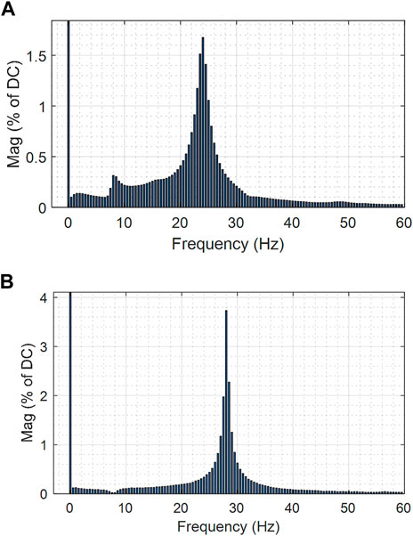
FIGURE 6. Spectrum analysis results of grid-side output current waveform under conditions (A) SCR = 1.8 (B) SCR = 3.
In the condition of SCR = 1.8, the system mainly focuses on the frequency of 8 and 24 Hz, and the harmonic content of 24 Hz is prominent. In the situation of SCR = 3, the system primarily focuses on the frequency of 28 Hz. The close agreement between the oscillation frequency analysis results obtained from the eigenvalue calculation and the spectrum analysis results of the time-domain simulation waveform confirms the accuracy of the eigenvalue calculation.
To identify the states with the highest relevance to the subsynchronous-frequency and low-frequency modes, participation factors are calculated for each eigenvalue, as shown in Table 2. The participation factors for the subsynchronous mode (Mode 1) and the low-frequency mode (Mode 2) are listed in Table 3. The participation factors with high significance are highlighted in bold.
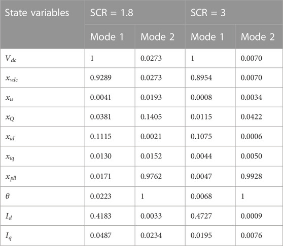
TABLE 3. Participation factor calculation results.
According to the results, we find that the subsynchronous oscillation mode (Mode 1) is related to the d-axis dynamics of GSC, especially the dynamics of DC, the outer DC voltage control and the d-axis component of line current. This finding concurs with the finding in (Liu et al., 2017). On the other hand, the low-frequency oscillation mode (Mode 2) is closely related to PLL, and this finding concurs with the finding in (Li et al., 2020b). In addition, the above two oscillating modes have little to do with inner current control. The stability analysis in Sections 4.2 and Section 4.3 examines the effects of the control links with large participation factors on each oscillation mode.
This section utilizes the developed small signal model, in the case of SCR = 1.8, to analyze the effects of relevant parameters on the damping ratio and oscillation frequency of the subsynchronous oscillation mode. Specifically, the root locus method is employed to investigate the influence of three factors: the proportional coefficient of the DC voltage control, the integral coefficient of the DC voltage control, and the DC capacitance.
To analyze the effect of the proportional coefficient of the outer DC voltage control on the subsynchronous oscillation mode, the proportional coefficient
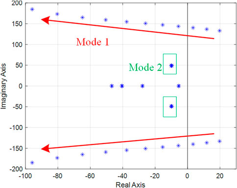
FIGURE 7. Root locus when
It can be seen from Figure 7 that the subsynchronous oscillation mode (Mode 1) is significantly affected by the proportional coefficient of the outer DC voltage control. As the proportional coefficient of the outer DC voltage control increases, the oscillation frequency of this mode increases and is in the subsynchronous frequency band. The damping ratio of this mode increases gradually with the rise of the proportional coefficient. As the proportional coefficient increases, the eigenvalue corresponding to Mode 1 moves toward the left half-plane. The critical condition for the instability of the study system is
Increase the integral coefficient
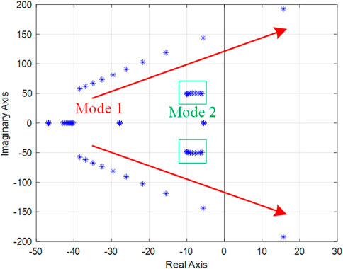
FIGURE 8. Root locus when
It can be seen from Figure 8 that the changes in the proportional coefficient of the outer DC voltage control have a significant impact on the subsynchronous oscillation mode. As the outer DC voltage control integral coefficient gradually increases, the frequency in this oscillation mode rises gradually. In addition, as the integral coefficient of the outer DC voltage control gradually increases, the damping ratio of this mode gradually decreases, and the corresponding eigenvalue gradually moves from the left half-plane to the right half-plane,
The PMSG wind turbines are connected to the grid through back-to-back converters. The DC capacitance between the two converters maintains power stability by charging and discharging. Moreover, the larger the DC capacitance, the less the dynamic impact of the PMSG machine side dynamics on stability. However, the DC capacitance cannot be infinitely large due to the limitation of actual conditions. The above analysis shows that the subsynchronous oscillation mode is closely related to the dynamic of the DC link. To investigate the impact of DC capacitance on the subsynchronous oscillation mode under weak AC grid conditions, we gradually increase the DC capacitance value from 10,000 to 50,000 μF while keeping other parameters constant (as listed in Table 1). Figure 9 shows the root locus of the study system:
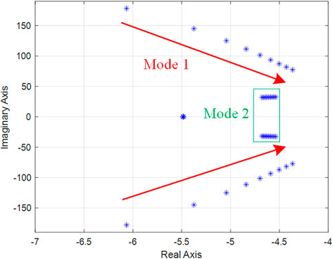
FIGURE 9. Root locus when DC Capacitance changes.
It can be seen from Figure 9 that the subsynchronous oscillation mode is significantly affected by the value of the DC capacitance. Increasing the DC capacitance has little effect on the damping ratio of the subsynchronous oscillation mode. However, as the DC capacitance rises, the oscillation frequency gradually shifts from subsynchronous to low-frequency. In practical PMSGs, the capacitance value is often set above 10,000 μF, leading to oscillation frequencies mainly in the subsynchronous frequency band for this mode. As expected, the low-frequency oscillation mode is relatively insensitive to changes in the DC capacitance value.
Based on the root locus and participation factor analyses, it has been determined that if the proportional coefficient of the outer DC voltage control is too small or the integral coefficient is too large, the subsynchronous oscillation mode may become the dominant mode, resulting in subsynchronous oscillation.
Under the condition of SCR = 1.8, this section conducts a detailed theoretical study on the characteristics of the low-frequency oscillation mode from the two aspects of the PLL proportional coefficient and the PLL integral coefficient. It deeply discusses the influence of the dominant factors on the damping ratio and oscillation frequency of the oscillation mode.
To analyze the effect of the PLL proportional coefficient on the low-frequency oscillation mode (Mode 2), the PLL proportional coefficient
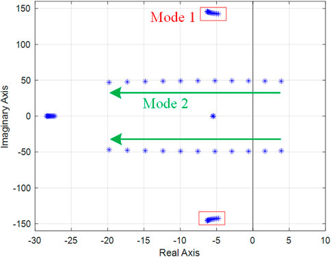
FIGURE 10. Root locus when
It can be seen from Figure 10 that the low-frequency oscillation mode is significantly affected by the PLL proportional coefficient
In order to analyze the influence of the PLL integral coefficient on the low-frequency oscillation mode, the PLL integral coefficient
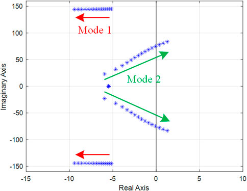
FIGURE 11. Root locus when
Figure 11 illustrates that the PLL integral coefficient
The characteristic root analysis and participation factor results indicate that the low-frequency oscillation mode may become dominant if the PLL proportional coefficient is too small or the integral coefficient is too large.
In order to verify the correctness of the theoretical analysis in Section 4.2 and Section 4.3 effectively, this section sets up two simulation cases based on the Simulink electromagnetic transient simulation model. The parameters not mentioned in the cases are set according to Table 1.
Case 1. Simulation verification of the influence of outer DC voltage control parameters on system stability.Under the condition of SCR = 1.8 and SCR = 3, the system operates at a steady-state operating point (
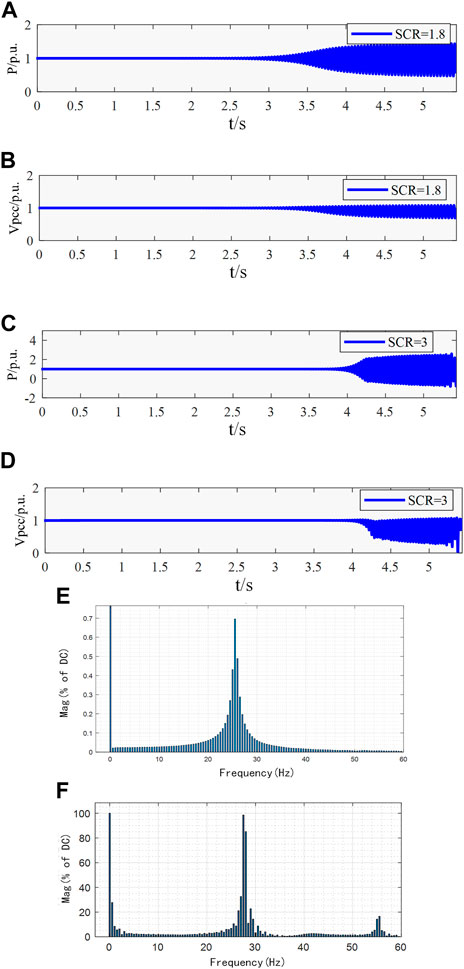
FIGURE 12. Time domain simulation results and spectrum analysis results of the active power output of GSC (A) the active power waveform under SCR = 1.8 (B) the voltage waveform of PCC under SCR = 1.8 (C) the active power waveform under SCR = 3 (D) the voltage waveform of PCC under SCR = 3 (E) spectrum analysis results of the active power under SCR = 1.8 (F) spectrum analysis results of the active power under SCR = 3.
Case 2. Simulation verification of the influence of PLL parameters on system stability.Under the condition of SCR = 1.8 and SCR = 3, the system operates at a steady-state operating point (
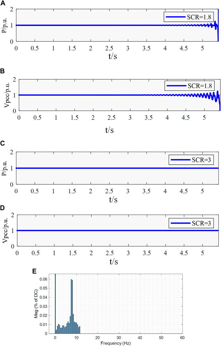
FIGURE 13. Time domain simulation and spectrum analysis results under the conditions (A) the active power waveform of the GSC under SCR = 1.8 (B) the voltage waveform of PCC under SCR = 1.8 (C) the active power of the GSC under SCR = 3 (D) the voltage waveform of PCC under SCR = 3 (E) spectrum analysis results of the active power output of GSC under SCR = 1.8.
This paper establishes the grid-side small signal model of the PMSG grid-connected system. Through the use of model analysis techniques, the performance of the small signal model is examined, revealing the root causes of oscillations in different frequency bands. The study concludes that the small signal model’s performance is close to that of the detailed electromagnetic transient model in terms of small signal stability. Thus, the machine-side dynamics of the PMSG wind farm can be disregarded in the small signal modeling to balance modeling speed and simulation accuracy. The study finds that the PMSG grid-connected wind farm exhibits subsynchronous and low-frequency oscillation modes. The dominance of the subsynchronous oscillation mode depends on the parameters of outer DC voltage control and the dynamics of the DC link, while the dominance of the low-frequency oscillation mode depends on grid strength and the parameters of the PLL. These findings can serve as a reference for the analysis of practical oscillation problems in PMSG grid-connected wind farms. Future research could focus on analyzing the impact of these two types of oscillations on the surrounding grid and exploring damping controls of oscillations.
The original contributions presented in the study are included in the article/Supplementary Material, further inquiries can be directed to the corresponding author.
LZ and LC conceived of the presented idea. LC and PH contributed significantly to the analysis and manuscript preparation and carried out the experiment. YW verified the correctness of the analysis method. ML and MX led the writing of the manuscript. All authors listed have made a substantial, direct, and intellectual contribution to the work and approved it for publication.
This work is supported by the Guangdong Provincial Key Laboratory of Intelligent Operation and Control for New Energy Power System (No. GPKLIOCNEPS-2021-KF-01).
Authors ML and MX were employed by China Southern Power Grid.
The remaining authors declare that the research was conducted in the absence of any commercial or financial relationships that could be construed as a potential conflict of interest.
All claims expressed in this article are solely those of the authors and do not necessarily represent those of their affiliated organizations, or those of the publisher, the editors and the reviewers. Any product that may be evaluated in this article, or claim that may be made by its manufacturer, is not guaranteed or endorsed by the publisher.
The Supplementary Material for this article can be found online at: https://www.frontiersin.org/articles/10.3389/fenrg.2023.1184119/full#supplementary-material
Bao, L., Fan, L., and Miao, Z. (2022). “Control interaction of STATCOM and type-4 wind turbines,” in 2022 IEEE Power & Energy Society General Meeting (PESGM), Denver, CO, July 17-21, 2022, 17–21.
Cheng, Y., Fan, L., Jonathan, R., Huang, S., Schmall, J., Wang, X., et al. (2023). Real-world subsynchronous oscillation events in power grids with high penetrations of inverter-based resources. IEEE Trans. Power Syst. 38 (1), 316–330. doi:10.1109/tpwrs.2022.3161418
Fan, L., and Miao, Z. (2018). Wind in weak grids: 4 Hz or 30 Hz oscillations? IEEE Trans. Power Syst. 33 (5), 5803–5804. doi:10.1109/tpwrs.2018.2852947
Fan, L. (2018). Modeling type-4 wind in weak grids. IEEE Trans. Sustain. Energy 10 (2), 853–864. doi:10.1109/TSTE.2018.2849849
Li, C., Liang, J., Cipcigan, L. M., Ming, W., Colas, F., and Guillaud, X. (2020a). DQ impedance stability analysis for the power-controlled grid-connected inverter. IEEE Trans. Energy Convers. 35 (4), 1762–1771. doi:10.1109/tec.2020.2989855
Li, Y., Fan, L., and Miao, Z. (2020b). Wind in weak grids: Low-frequency oscillations, subsynchronous oscillations, and torsional interactions. IEEE Trans. Power Syst. 35 (1), 109–118. doi:10.1109/tpwrs.2019.2924412
Liu, F., Li, Y., He, G., Li, G., Liu, S., and Liu, W. (2022). Small signal modeling and stable operation strategy analysis of direct drive wind power grid-connected converter in extremely weak power grid. Electr. Power Autom. Equip. 42 (8), 167–173. doi:10.16081/j.epae.202204086
Liu, F., Liu, W., Wang, H., Xie, Z., Yang, S., and Wang, J. (2021). “Small signal modeling and discontinuous stable regions of grid-connected inverter based on pade approximation,” in 2021 IEEE 12th Energy Conversion Congress & Exposition - Asia (ECCE-Asia), Singapore, May 24-27, 2021, 24–27.
Liu, H. K., Xie, X. R., He, J. B., Xu, T., Yu, Z., Wang, C., et al. (2017). Subsynchronous interaction between direct-drive PMSG based wind farms and weak AC networks. IEEE Tran. Power Syst. 32 (6), 4708–4720. doi:10.1109/tpwrs.2017.2682197
Shao, B., Zhao, S., Yang, Y., Gao, B., and Blaabjerg, F. (2021). Sub-synchronous oscillation characteristics and analysis of direct-drive wind farms with VSC-hvdc systems. IEEE Trans. Sustain. Energy 12 (2), 1127–1140. doi:10.1109/tste.2020.3035203
Strachan, N. P. W., and Jovcic, D. (2010). Stability of a variable-speed permanent magnet wind generator with weak AC grids. IEEE Trans. Power Deliv. 25 (4), 2779–2788. doi:10.1109/tpwrd.2010.2053723
Wang, K., Yuan, X., Wang, H., Zhang, Y., and Wu, X. (2023). Two causes of the inverter-based grid-connected system instability in weak grids. Power Syst. Technol. 47 (3), 1230–1242. doi:10.13335/j.1000-3673.pst.2021.2436
Xiao, S., and Xu, L. (2022). Analysis of key factors and suppression measures for sub-synchronous oscillation of direct-drive PMSG based on frequency coupled impedance. Power Syst. Technol., 1–14. doi:10.13335/j.1000-3673.pst.2022.0778
Xie, X., Liu, H., He, J., Zhang, C., and Qiao, Y. (2016). Mechanism and characteristics of subsynchronous oscillation caused by the interaction between full-converter wind turbines and AC systems. Proc. CSEE 36 (9), 2366–2372. doi:10.13334/j.0258-8013.pcsee.2016.09.007
Xu, L., Guo, C., Peng, Y., Yang, S., and Zhao, C. (2020). “Small signal model of VSC-hvdc considering the impact of time delay,” in 2020 10th International Conference on Power and Energy Systems (ICPES), Chengdu, December 25-27, 2020, 25–27.
Xu, Y., and Cao, Y. (2018). Sub-synchronous oscillation in PMSGs based wind farms caused by amplification effect of GSC controller and PLL to harmonics. IET Renew. Power Gener. 12 (7), 844–850. doi:10.1049/iet-rpg.2017.0740
Keywords: small-signal stability, oscillation, converter control, permanent magnet synchronous generator (PMSG), grid strength, phase-locked loop (PLL)
Citation: Zhu L, Chen L, Hu P, Wu Y, Liao M and Xu M (2023) Performance analysis of modeling scale on multiband oscillations in grid-connected wind farm. Front. Energy Res. 11:1184119. doi: 10.3389/fenrg.2023.1184119
Received: 11 March 2023; Accepted: 09 May 2023;
Published: 23 May 2023.
Edited by:
Changhui Liu, China University of Mining and Technology, ChinaReviewed by:
Rui Wang, Northeastern University, ChinaCopyright © 2023 Zhu, Chen, Hu, Wu, Liao and Xu. This is an open-access article distributed under the terms of the Creative Commons Attribution License (CC BY). The use, distribution or reproduction in other forums is permitted, provided the original author(s) and the copyright owner(s) are credited and that the original publication in this journal is cited, in accordance with accepted academic practice. No use, distribution or reproduction is permitted which does not comply with these terms.
*Correspondence: Lin Zhu, emh1bEBzY3V0LmVkdS5jbg==
Disclaimer: All claims expressed in this article are solely those of the authors and do not necessarily represent those of their affiliated organizations, or those of the publisher, the editors and the reviewers. Any product that may be evaluated in this article or claim that may be made by its manufacturer is not guaranteed or endorsed by the publisher.
Research integrity at Frontiers
Learn more about the work of our research integrity team to safeguard the quality of each article we publish.