
95% of researchers rate our articles as excellent or good
Learn more about the work of our research integrity team to safeguard the quality of each article we publish.
Find out more
ORIGINAL RESEARCH article
Front. Energy Res. , 21 August 2023
Sec. Energy Storage
Volume 11 - 2023 | https://doi.org/10.3389/fenrg.2023.1180531
This article is part of the Research Topic Low Carbon Design, Manufacturing and Application of the Energy Storage System and Equipment View all 5 articles
 V. Mounica
 Y. P. Obulesu*
This study describes a multi-input power system that is suited for fueling electric automobiles, InterCitys, and airplanes, particularly in situations with significant fluctuating load demand. The dual framework utilizes fuel cells (FC), batteries, and super capacitors (SCs). An energy management system (EMS) remains a critical aspect of lowering overall hydrogen consumption and minimizing the degradation of FC functionality. A novel EMS that has been suggested focused on a novel optimization method known as the Coyote optimization algorithm (COA), and it considers the fact that the total load is adequately supplied within the limitations of each power source. To minimize the hydrogen consumption. By maximizing the power generated by the energy storage devices, the energy acquired from the FC is reduced. In comparison to other optimization methods, the COA would be a practical, effective, and relatively straightforward optimizer that only involves a limited number of controlling factors to be set. The framework application MATLAB/Simulink is used to create the proposed method. In order to show the effectiveness of the proposed methodology, a study with several different conventional techniques is performed, which includes the classic proportional-integral control mechanism, the frequency decoupling with state machine (FDSM) controlling technique, the equivalent consumption minimization scheme (ECMS), and the external energy minimization scheme (EEMS). The efficacy of the algorithm and the FC’s aggregate H2 usage serve as the focal points for comparison in this work. The outcomes demonstrate that the recommended COA strategy is superior and more effective than the alternative approaches.
Nowadays, environmental protection, decrement in conventional energy storage systems, and emission-free energy storage classifications affect performance in many parts of the world. Conventional vehicles are mainly designed with internal combustion engine (ICEs) which uses fossil fuel; these vehicles release harmful emissions and high noise, and the cost of fuel is high. To solve these issues, Dr. Ferdinand Porsche developed the first electric vehicle (Egger-Lohner vehicle) in the year 1898. Electric vehicles (EVs) are divided into several categories, including battery electric vehicles (BEVs), plug-in hybrid electric cars (PHEVs), hybrid electric vehicles (HEVs), and fuel cell hybrid electric vehicles (FCEVs). These models have distinct characteristics like BEVs and have a low driving range, but the mode is emission-free and makes low noise. HEVs have both an electric and gasoline engine (ICE) and the model is not emission-free, but the driving range is high depending on energy sources. The PHEV has high efficiency when compared to BEV and HEV but this model requires an external source for charging the batteries (Banaei et al., 2020; Bauman et al., 2008; Meng et al., 2019; Galdi et al., 2006; Buccoliero et al., 2019; Li et al., 2019). The fuel cell hybrid electric vehicle was proposed to attain a higher driving range, be emission-free, and make low noise; moreover, it also overcomes the issues of the previous models, but the FHEV is a bit costly.
A power management scheme (PMS) is required to accomplish certain hybridization and meet the main purpose of spreading load requirements through power sources. The PMS considerably reduces hydrogen consumption and improves energy efficiency by limiting fuel cell performance to wider operating levels. A traditional PMS was implemented to control the system load among various integrated input sources.
As per the American Department of Energy Studies, the proton exchange membrane fuel cell technology has been improved to 5,000 h in real-world settings with 10% less degradation; however, it is presently not over 2,500 h (Carignan et al., 2018; Khan et al., 2018; Kandidayeni et al., 2019; Wu et al., 2019; Yuan et al., 2019; Liu et al., 2020). The PEMFC is one of the types of fuel cells that help in the propulsion system for a long time. Nowadays, PEMFC has been used in many automotive HEVs because of the friendly environment, and it increases the autonomy of EVs. Sir William Grove first developed the fuel cell in 1839. Mainly, fuel cells are categorized into many types based on their characteristics. In this work, the HEV with the PEMFC has been considered because of its high energy density, lightweight, and ability to operate at low temperatures. A major part of a hybrid electric vehicle is its multiple input sources; it consists of the li-ion battery bank, ultra-capacitors/super capacitors bank, and PEMFC, utilizing different combinations because a single source alone cannot meet the requirements of the load (Khaligh et al., 2010; Penina et al., 2010; Itani et al., 2017; Pierezan and Leandro Dos, 2018; Rezk et al., 2019; Kwan et al., 2020; Lee et al., 2020; Li et al., 2020; Xiao et al., 2021).
A supercapacitor (SC) and fuel cell are used as a Hybrid energy storage system (HESS) for the HEV in (Sun et al., 2020). In (Zhang et al., 2020), the battery and fuel cell are considered an HESS in the HEV. These combinations show that it is not able to accomplish the requirement of a DC bus and HEV. Yuan et al. (2020) proposed HESS as a fuel cell/SC/battery; it is a realistic approach for attaining high-power density and energy, and the energy storage capacity is also more. Hybridization of fuel cells, Li-ion batteries, and SC leads to better fuel economy, and these batteries and SC provide a better part of load performance.
The HESS relates to uni-directional and bi-directional DC-DC converters for efficient exchange of power. Various configurations of converters for HEV are addressed in Rezk et al. (2021) to distribute the power of HESS to load or load to HESS through different power management strategies (PMS). In designing the proper PMS, it will achieve the optimal economy of fuel. PMS should be limited as much as possible in hybrid energy sources because it can impact the life cycle of hybrid sources.
Kamel et al. (2020) developed state machine control; it is a simple design. The design comes under a rule-based scheme based on heuristic previous experience with the PMS in each state or under the rules that were developed. Here, the performance mainly depends on the designer of the system, particularly how well it is appropriate to the operation of all the components in the system. Tao et al. (2020) implemented a rule-based fuzzy logic PMS. The power exchange was done by the membership functions, and it was also done by a set of IF-THEN rules. Here, the fuzzy controller was based on IF-THEN rules that mainly required experience and knowledge. This strategy could be tuned easily for optimal operation of the system (Yue et al., 2019; Imran et al., 2020; López-Pérez et al., 2020; Chen et al., 2019; Ouddah et al., 2019; Alam et al., 2020).
The classical PI controller was proposed by Nguyen et al. (2020). It controlled mainly the state of charge of the battery, DC Bus voltage, and UC voltage by using PI control. These control schemes could be tuned easily and it could be done by online tuning for better tracking (Tian et al., 2019; Chen et al., 2020; Lee et al., 2020; Li et al., 2020; Ostadian et al., 2020; Sun et al., 2020; Niu et al., 2022). Here, the power of the load was exchanged predominantly to provide steady-state demand of load by using the fuel cell system. Xu et al. (2019) designed a frequency decoupling scheme. It ensured that the SC and batteries provided high-frequency demand, whereas fuel cells provided low-frequency demand through the wavelet, filter, and rapid Fourier transform approaches. The frequency decoupling scheme prevented the stresses on the primary source and improved the lifetime of the proton exchange membrane fuel cell. Constant mean load power was provided by the chief source (Hegazy et al., 2012; El Fadil et al., 2014; Rajabzadeh et al., 2016; Armghan et al., 2018; Li et al., 2019; Demircali et al., 2020; Sai Chandan et al., 2020). In cases where the power of the load was higher or lower than the mean value, SC and batteries will charge and discharge, respectively. Wang et al. (2020) proposed a cost function optimization technique for better operation of the fuel cell to attain maximum global efficiency and fuel economy. The equivalent fuel consumption minimization approach (ECMS) was developed for rapid application. The power exchange was governed by the instantaneous cost function minimization. It consisted of two-way-like consumption of fuel in the overall fuel cell system and equivalent consumption of fuel in SC and battery (Shen et al., 2015; Min et al., 2023).
Real-time PMS for HESS is model predictive control (Njoya Motapon et al., 2014), neural networks, H-infinity, dynamic programming, and adaptive optimal control. These types of PMS are complex and require larger computations. It mainly affects the PMS response time (Hu et al., 2020; Tifour et al., 2020; Yang et al., 2022).
In this paper, the coyote algorithm-based power management scheme for hybrid electric vehicle applications is implemented by utilizing a hybrid energy storage system. It can manage the energy among fuel cells and batteries through the extremely varied state of the load. The performance of PEMFC depends on many operating parameters like temperature, humidity, and pressure, and it also depends on the degree of degradation performance. This paper is systematized as ensues. Section 2 labels the mathematical modeling of HESS. Section 3 represents power management strategies. Section 4 focuses on the comparison of different PMS. Finally, Section 5 presents the conclusion of the research work and scope followed by references.
The structure of the hybrid electric vehicle (HEV) test system is seen in Figure 1. The fuel cell, rechargeable battery, and supercapacitor are the three sources of power as shown in this setup.
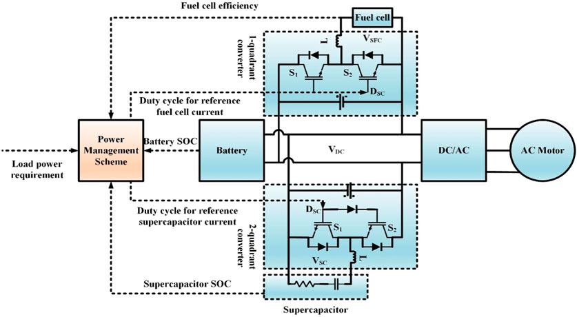
FIGURE 1. Architecture of hybrid electric vehicle (HEV) test system.
A DC/DC boost converter has been used with the fuel cell to enhance its voltage level toward the desired level and sustain this at the outputs. Supercapacitors have been integrated into bi-directional converters which enable power to be exchanged in both directions. The HESS is concerned with uni-directional as well as bi-directional DC-DC converters for efficient power exchange to allocate HESS energy to load or load to HESS using various power management strategies/schemes (PMS). The optimum fuel economy can be achieved when creating the proper PMS. PMS must be kept to a minimum in hybrid energy sources because it has the potential to shorten their life cycle. Load power is calculated by using Equation.(1)
The battery is designed with a modest controlled power supply in series with such a fixed resistance. Eq. 2 defines the battery voltage Vbat (2).
The controlled source voltage is calculated by using Eq. 3.
Where E represents no load voltage (V),
A fuel cell is a power conversion device that converts chemical energy in hydrogen fuel to electrical power without using heat or mechanical power. As per the chemical process defined in Eq. 4, the basic working principle of a fuel cell is described by a chemical process in which oxygen and hydrogen are linked together to form power, heat, and water.
There are several types of fuel cell technologies that are categorized depending on their electrolytes. Another type of fuel that is widely used in vehicular applications is Proton Exchange Membrane Fuel (PEMFC). There are several new fuel cell prototypes, each with a combination of benefits and drawbacks based on the topic under study. Any model must be concise and accurate. Furthermore, this paper presents a simple electrochemical concept that might be used to determine the behavior of such fuel cells both in dynamic and static conditions. A hydrogen fuel design used in this study was based on the interaction between the fuel cell voltage level and hydrogen, water, and oxygen absolute pressures. The detailed layout of an FC is utilized as a controlled supply voltage. A fuel cell voltage is regulated via oxygen and hydrogen relative pressure, the chemical process temperature of membrane hydration, and the output current. The mathematical model is given as:
Where
where.
Hence, For N no. of cells connected in series, the stack voltage
The fuel cell’s polarization curves indicate the voltage of the battery as a factor of output current. Under several temperatures and hydrogen pressure levels, the following and above results can be seen Overall polarization patterns for FCs increase as that of the optimal temperature and hydrogen pressure reduce. As much as this is provided by oxygen and fuel to sustain a chemical reaction mechanism, a fuel cell can produce a constant amount of power. Proton exchange membrane fuel cells are widely used in automotive applications due to their high-power density and low and moderate operating temperatures. Furthermore, its effectiveness when reacting under peak load has been restricted because of certain chemical processes which occur in FC. As an outcome, such sources are integrated into the batteries as well as the supercapacitor-based hybrid storage systems.
Normally, DC/DC converters are divided into two categories based on whether or not they utilize galvanic isolation. As an outcome, a non-isolated or isolated circuit might be built. Non-isolated converters appear to be simple, but to minimize ripple current, a significant input inductor is required. As a response, for protective measures, isolation only between outputs and inputs is often essential. Under this work, an isolated DC/DC converter has two main components: a high-frequency DC-AC converter and an AC-DC converter, which are separated by a transformer to maintain the galvanic isolation between the fuel cell and the load. As a response, high-frequency operations minimize the converter’s weight and size. The power converter’s design can be seen in Figure 2. It is used to create the electrical connection between both the fuel cell and the DC bus. Through this converter, uni-directional current DC-DC conversion is performed. These converters modify the batteries’ voltage range at the DC link in charging mode.
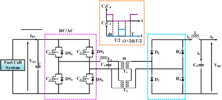
FIGURE 2. Uni-directional converter topology.
A converter’s voltage output should be regulated toward the DC bus voltage. As a result, including a proportional-integral controller (PI) to operate the converters is required, as shown in Figure 3.
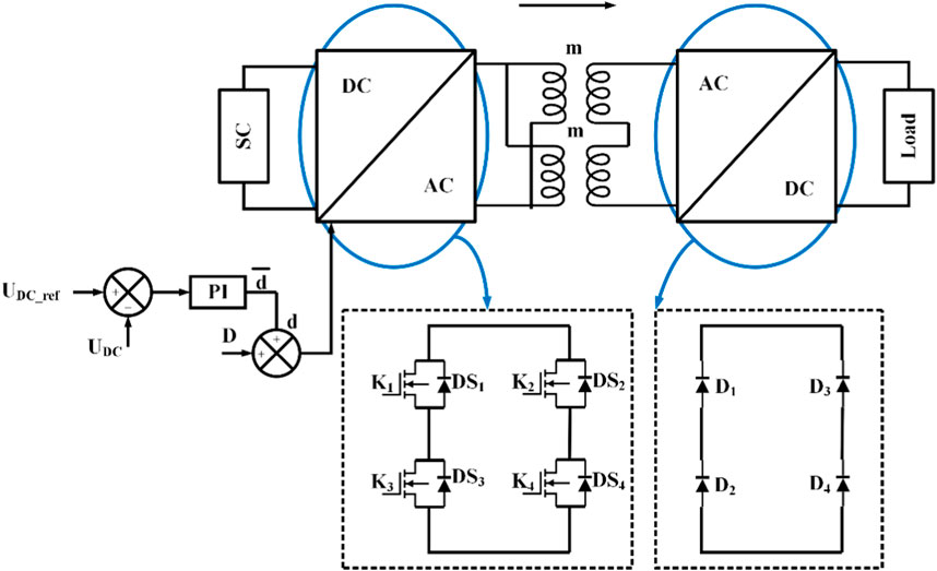
FIGURE 3. Control strategy of uni-directional converter output voltage.
Both the output capacitor voltage and its inductor current were considered state variables to determine the typical design of a DC/DC converter. As selected variables, an FC voltage and its current demand are specified. The equation for state space formulation (8) is as follows.
Where,
The given mathematical model describes the state representation of a converter model during period T as such a parameter on duty ratio d:
Supercapacitors are one of the recent advancements for power storage devices, especially integrated devices. A capacitance Csc is linked to an equivalent series resistance Rsc under this setup. The below formula is used to determine a supercapacitor voltage Vsc as a result of SC current Isc:
Where,
Utilizing supercapacitors like a storage system in such an electric vehicle implies the construction of such stacking of cells, where Ns cells are interconnected in series and Np cells are parallel connected. Eqs 13, 14 determine the capacity and resistance of the supercapacitor stack.
Eqs 15, 16 determine both the current and voltage of a stack as a measure of such component current and voltage.
Both batteries and supercapacitors are employed to store energy in the transportation system under investigation. Two-way current converters are designed to transfer power both ways and are required to connect these two parts toward the DC link. Some of these converters are assembled by using various components.
- Four transistor-diode pairs are comprised of a full bridge ultracapacitor.
- The four-transistor-diode set full bridge end DC bus has been used.
- With the use of winding inductance, two different planar transformers supply galvanic isolation as well as power storage.
Because all these converters linked by SC and also battery were comparable, then the focus was on the one that was related to capacitors in this study. Figure 4 depicts the topologies used in this study.
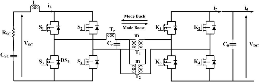
FIGURE 4. Bi-directional converter topology.
Two proportional integral controllers are used to regulate the two converters (DC/AC) and (AC/DC). As a result, as indicated in Figure 5, its converter’s output voltage can be controlled toward the DC link voltage.
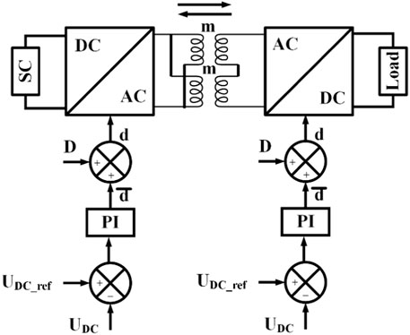
FIGURE 5. Control of Bi-directional converter output voltage.
Multiple system parameters, namely, converter output voltage and inductor current, were considered as model parameters for modeling the converters connected with capacitors, and even the supercapacitor voltage or current required was preferred as dependent variables, relating to a situation of a fuel cell.
A) Boost mode operation (Ultra-capacitor Discharging)
The set of calculations in Eq. 17 represents the state characterization of the converters model when it is working in boost mode.
The matrices A1, B1, and C1 are calculated using Eqs 18, 19
with;
B) Buck mode operation (Ultra-capacitor charging)
In this case, Eq. 22 denotes the state classification of the converter layout under buck mode.
In the FCHEV, managing the power between HESS(FC/B/SC) enhances the better performance of the hybrid storage system. The traditional EEMS employs (fmin) as a function from a Matlab toolbox. Consequently, for enhancing the performance, the (fmin) function is replaced by a recent optimization algorithm called the coyote optimization algorithm (COA). In the process of optimization, the input and output variables are fuel cell output power (PFC), battery state of charge (SOC), and power (Pbatt, SOCbatt). The upper limits and lower limits are given as
In this EEMS technique, hydrogen consumption (H2) is minimized by raising the battery and SC demand. EEMS technique requires the battery and SC cost function; it does not require the determined battery energy calculation. From Figure 4, it is shown that the EEMS algorithm inputs are DC bus voltage and state of charge of the battery or supercapacitor and the outputs are charge/discharge voltage (∆V) supercapacitor and battery reference power. Hence, comparing the battery and load power, the FC’s reference power via FC current (
In the EEMS optimization process, based on the power produced by the battery, the objective function is subjected to inequality constraints and the constraints are subject to
Whereas the power of the battery and voltage of the DC bus parametric inequality constraints are formulated as follows:
Here, P_batt.∆T denotes the delivered battery power over a sampling time (∆V). C_r represents the rated capacitance of SC. V_DC^min and V_DC^max denote the minimum and maximum limit of DC bus voltage. V_batt represents the battery’s nominal voltage. Q denotes the battery-rated capacity.
From Eq. 26, for maximizing the objective function, the proposed COA uses a COA optimizer by considering the constraints in Eq. 27. The configuration of the COA algorithm is shown in Figure 5. The inputs of COA are the state of charge of the battery and voltage of the supercapacitor, while the outputs of COA are supercapacitor charge/discharge voltage and reference power of the battery, in which these are compared with the supercapacitor voltage and load.
The PI controller supplies the required current to the battery converter and the conflicts between the voltage of the supercapacitor and reference are adjusted by this controller. Here, the contrast between the power of the battery and demand is subjected to the fuel cell reference current.
In 2018, Perez an et al proposed a coyote optimization algorithm (COA). This is a metaheuristic type of algorithm; the idea was inspired by the species called Canis latrans species which lives in North America. In the optimization process, the COA algorithm can manage a balance between the exploitation phase and the exploration phase. COA mainly depends on acting the coyotes, and it experiences the coyotes’ interchanging performance. Figures 6, 7 shows block diagram and birth and death rules of Coyote optimization algorithm. Coyotes can identify a prey location and they also have a strong sense of smell.
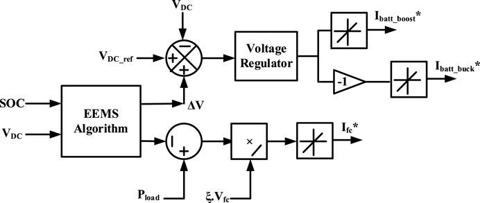
FIGURE 6. External energy maximization scheme.
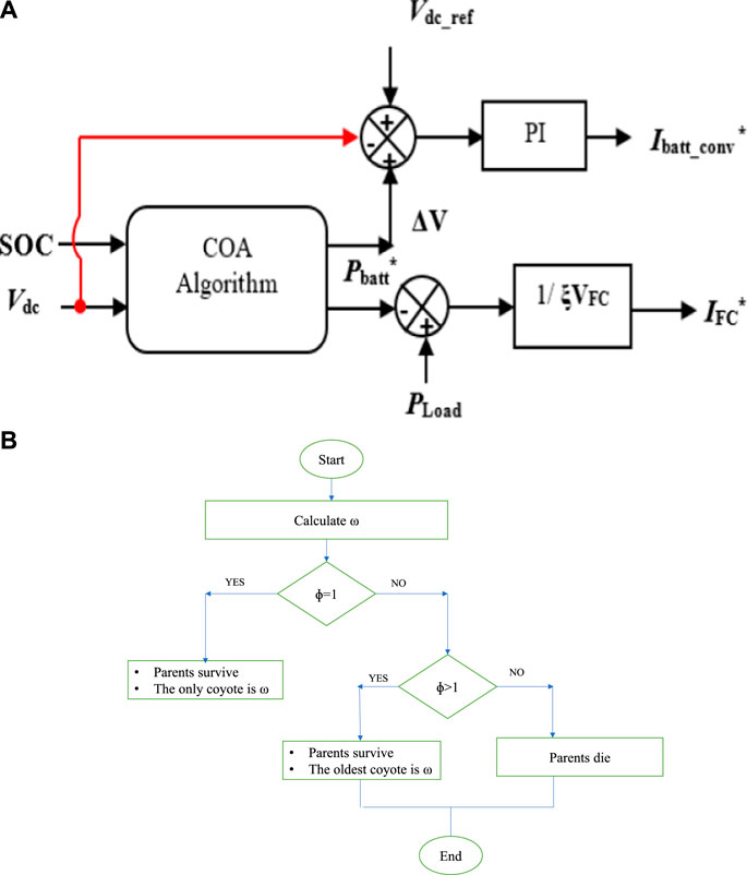
FIGURE 7. (A) Block diagram of the Coyote Optimization algorithm (COA), (B) Birth and Death rules of the Coyote Optimization algorithm (COA).
In COA, the initiation of the population is split into no. of packs (NP) with no. of coyotes (NC). In a Pth pack, the optimization process starts with coyotes initialization, social condition, and global population; the state of charge of Cth coyote in Pth pack is calculated as follows:
Here, the designed variables of upper and lower limits are
At the beginning of the optimization process, the coyotes are randomly allocated to packs. In some cases, coyotes leave their packs or join another pack; this act can arise with a probability of
The various waveforms of the uni-directional converter, which is designed for fuel cells, are presented in Figure 8. Figure 8A shows the change in load current waveform. Figures 8B, D show the effect of load current fluctuation on fuel cell voltages and currents. Due to the use of the PI controller, the converter output voltage [shown in Figure 8C] remains stable even when a large load current is desired. As a result, as seen in Figure 8E, the duty ratio is based on the load current.
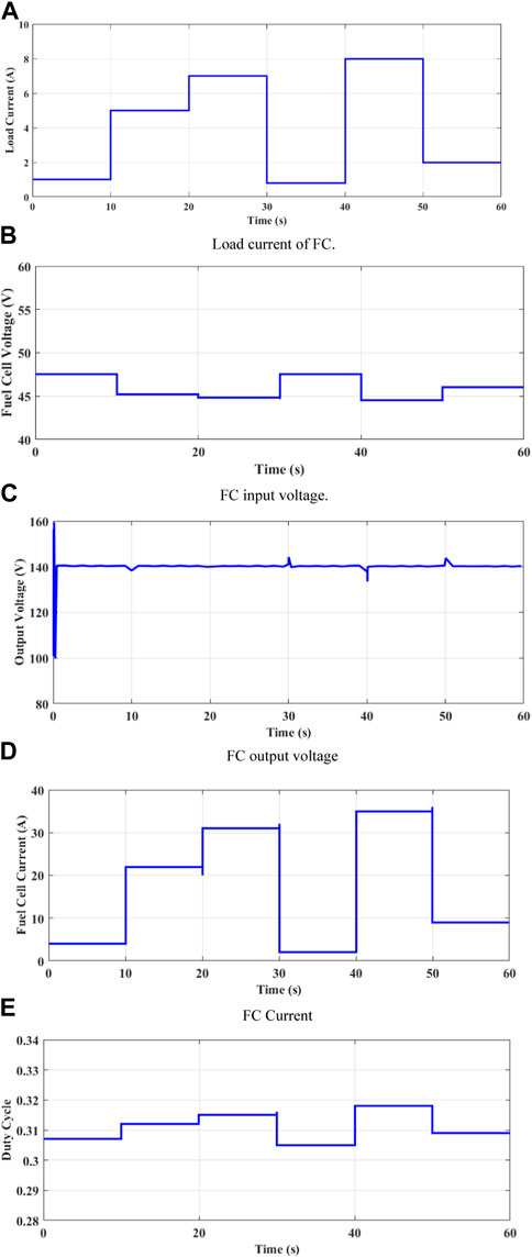
FIGURE 8. Waveforms of the Uni-directional DC/DC converter (A) Load current of FC. (B) FC input voltage. (C) FC output voltage. (D) FC Current. (E) The duty cycle of the uni-directional converter.
The simulation results of a supercapacitor connected to a DC/DC buck-boost converter in terms of improving the reliability and efficiency and how the load current often affects the supercapacitor are shown in Figure 9. Figure 9 depicts the simulation outcomes. As a result, the supercapacitor current and voltage are shown in Figures 9B, C for the load current shown in Figures 9A, D. Because the load current has both positive and negative levels, the supercapacitor is either charging or draining depending on the current direction, as shown by the state of the charge waveform in Figure 9E. Despite current variations, the output voltage is kept stable and identical to the set point, allowing the PI regulator’s performance to be confirmed. Figure 9F depicts its duty cycle. It fluctuates in response to changes in current in terms of managing the converter and keeping the output voltage even at the base value.
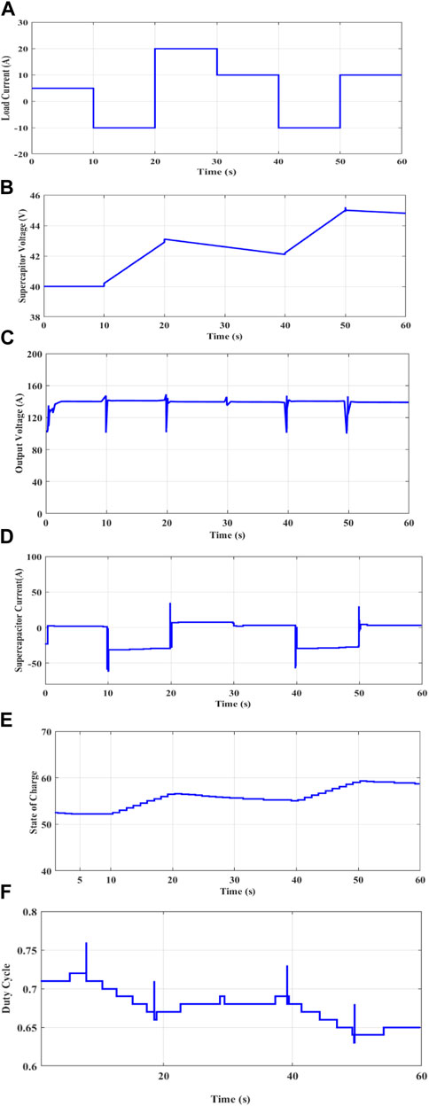
FIGURE 9. Waveforms of the Bi-directional DC/DC converter (A) Load current of SC. (B) SC input voltage, (C) SC Output voltage, (D) SC current, (E) State of charge of SC, (F) The duty cycle of the directional converter.
Different power management approaches for hybrid storage architectures were implemented. Each power management system was implemented with the same initial conditions: the state of charge of the battery was 70%, the temperature of the battery was 30 C, the voltage of the supercapacitor was 270 V, the temperature of the supercapacitor was 25 C, the voltage of the fuel cell was 52 V, and the temperature of the fuel cell was 40 C. The FC/B/SC model included a 12.5 KW, 30–60 V PEMFC, a 48 V, 40 Ah Li-ion battery, and a pair of 15.6 F, 291.6 V-6 series-connected supercapacitors. Two DC/DC converters managed the battery storage. The converter discharged the battery in a 4 KW boost mode and charged the battery in a 1.2 KW buck mode. A comparison of alternative power management systems is based on hydrogen consumption, overall efficiency, fuel cell and battery stress. Figures 10, 11 show the consumption of hydrogen (in Ipm and grams), and Figure 12 shows the total efficiency of all power management strategies. The stress evaluation for fuel cell, battery, and supercapacitor energy was done at 270 V DC using the Haar wavelet technique. Haar wavelet decomposition was used to assess power deterioration in low- and high-frequency equipment. The component with the highest frequency has a zero-mean value, and the standard deviation (σ) of this module offers more information on how a distinct storage system is maintained. The quantity of hydrogen consumed (in grams) is stated as:
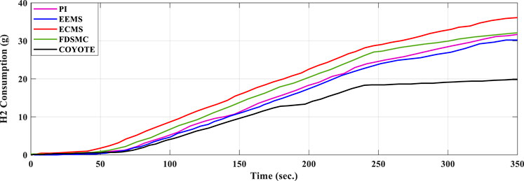
FIGURE 10. Time-responses of Hydrogen consumption in grams.
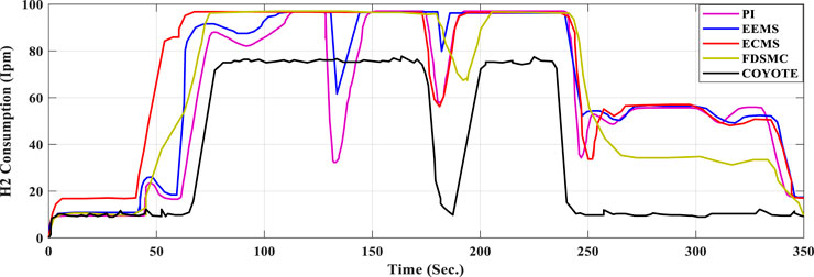
FIGURE 11. Time-responses of Hydrogen consumption in Ipm.
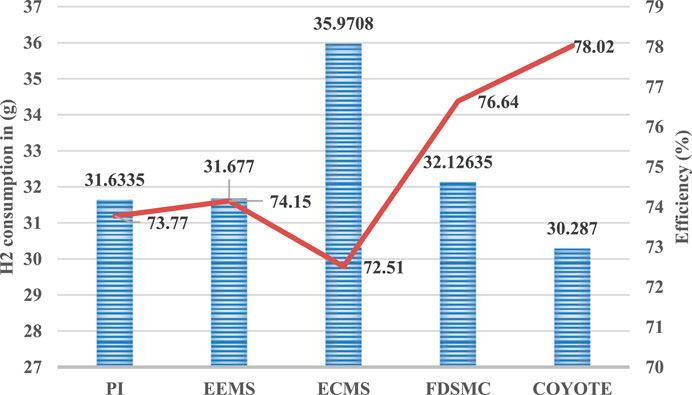
FIGURE 12. System efficiency and hydrogen consumption for each scheme.
Here, F= Faraday fundamental (A.s/mol).
Global efficiency is represented as,
Here,
The battery is quickly discharged while the primary source-fuel cell controls the load and recharges to reach the SoC reference in the traditional PI technique. In the case of state machine control, the fuel cell charges supercapacitors beyond their reference voltage (270 V) when the SoC of the LI-ion battery bank reaches its minimal limit, requiring the DC bus to regulate in order to charge the batteries. As opposed to other strategies, the frequency decoupling fuzzy logic strategy uses fuel cells to supply constant power, allowing the battery to recharge. Higher battery power is employed, which improves the performance of an equivalent consumption minimization strategy and an external energy minimization technique. In Figures 13, 14, the fluctuation of the battery SOC voltage and current is depicted.
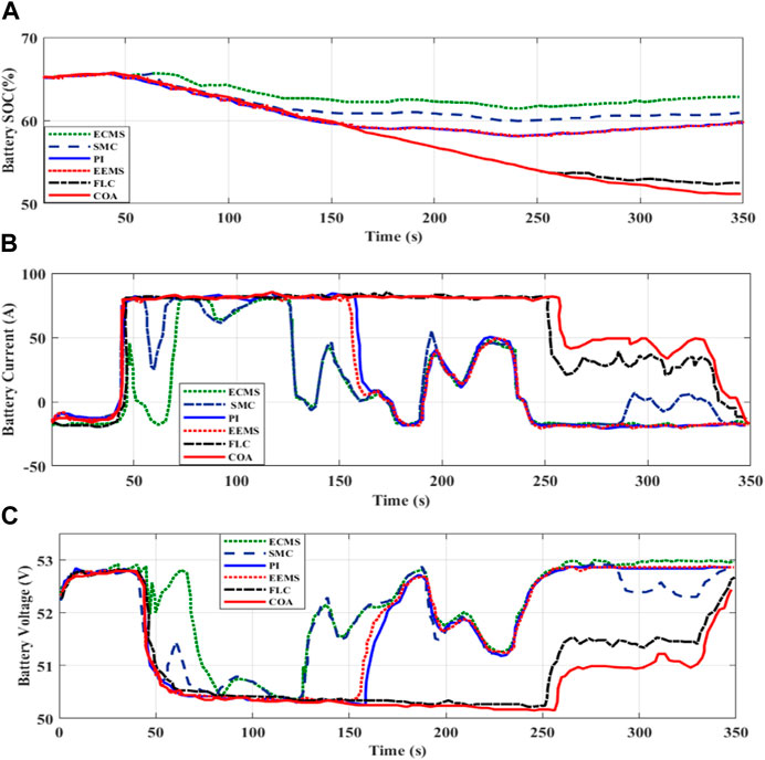
FIGURE 13. Time responses of battery SOC, current, and voltage (A) SOC of Battery, (B) Battery Current, (C) Battery Voltage.
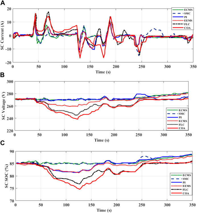
FIGURE 14. Time responses of supercapacitor SOC, current, and voltage (A) SC Current (B) SC Voltage (C) SOC of SC.
Since the Li-ion battery and UC are almost at the same level of charge, it follows that they will both be completely charged when the primary input is turned off. The battery and UC currents can now be raised. As a result, the interface voltages of the UC and batteries decrease as they are used to satisfy the rising load need. The load is changed at the same time that the battery and UC conditions are altered.
This indicates that the power produced by the battery bank and the UC bank is superior to the power supplied by the FC for delivering the necessary load, resulting in the lowest hydrogen usage.
As seen in Figure 15, the electricity for the load was provided by hybrid energy sources (FC, B, and UC), and the overall comparison of EMS schemes is shown in Table 1. The system’s performance was measured over a period of 350 s, starting at time zero, when there was no demand for the load and no-load power. In this instance, the fuel cell charged the battery. The power supply to batteries and supercapacitors was distributed during the 1940s, while fuel cell power steadily increased at the same time. At 45 s later, the voltage level in the supercapacitor dropped to the reference value of 270 V. At time t = 60 s, the supercapacitor was supplying more transient demand than the primary source’s maximum power, while the power of the fuel cell was increasing primarily. Therefore, additional fuel cell power was used to charge the secondary sources. As a result of the decreasing load requirement at 330 s, the power of the primary source likewise gradually decreased when recharging the battery container.
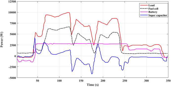
FIGURE 15. Power of hybrid sources (fuel cell, Li-ion battery, and super capacitor) delivering the load request versus time.
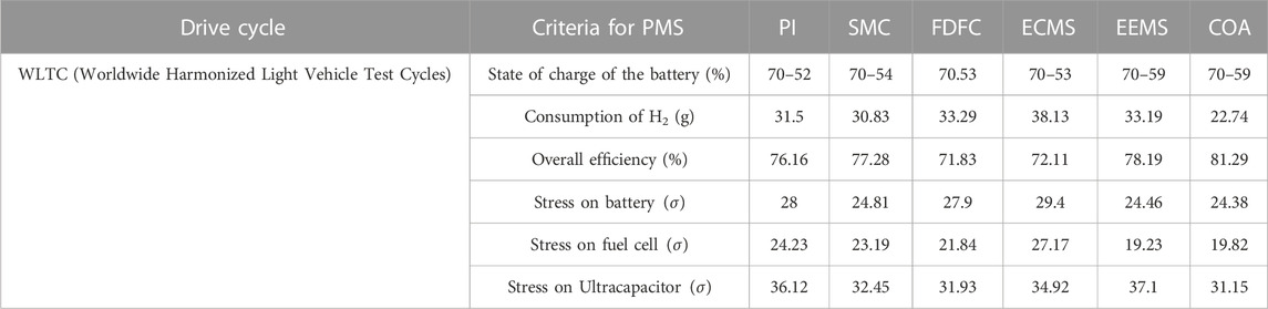
TABLE 1. Overall performance of each PMS scheme.
In order to manage the energy in the hybrid-producing system made up of fuel cells, batteries, and supercapacitors as efficiently as possible, this work proposes a contemporary optimization technique known as COA. To supply the rapidly fluctuating demand, the hybrid system is connected to a DC-DC converter. As a backup emergency supply, the hybrid-producing system/hybrid energy storage system is being provided for optimization. By optimizing the energy supplied by both the batteries and the supercapacitors, the primary goal is to decrease overall hydrogen consumption. The COA is used by the authors because of its simplicity and need for a few control settings, among other benefits. The suggested COA’s outcomes are contrasted with those of other traditional and heuristic methods, including state machine control strategy, rule-based fuzzy logic strategy, classical proportional integral control strategy, equivalent consumption reduction strategy, and genetic algorithm. The comparison focuses on how much hydrogen is consumed and how effective the plan is. With just 30.28 g of hydrogen used and a 78.02% efficiency, the suggested method is discovered to be superior to the other alternatives. The outcomes of the suggested COA’s analysis support the approach’s validity and superiority in terms of achieving the best possible energy management for the hybrid generating system. The findings showed that the suggested COA may greatly reduce energy consumption when high-frequency operation of transportation vehicles, such as high-speed trains and aircraft, is used. Applying another cutting-edge optimization method will allow this work to be expanded upon and refined in the future. The overall cost of operating the system and the voltage control of each source are two additional objective functions that may be considered.
The original contributions presented in the study are included in the article/Supplementary material, further inquiries can be directed to the corresponding author.
Conceptualization, VM and YO; supervision, YO; validation, VM; visualization, VM; writing–original draft, VM and YO; writing–review and editing, VM and YO. All authors contributed to the article and approved the submitted version.
The authors declare that the research was conducted in the absence of any commercial or financial relationships that could be construed as a potential conflict of interest.
All claims expressed in this article are solely those of the authors and do not necessarily represent those of their affiliated organizations, or those of the publisher, the editors and the reviewers. Any product that may be evaluated in this article, or claim that may be made by its manufacturer, is not guaranteed or endorsed by the publisher.
EV, Electric Vehicle; EMS, Energy Management Structure; HEVs, Hybrid Electric Vehicles; COA, Coyote Optimization algorithm; PMS, Power Management Strategy; PI, Proportional Integral; BESSs, Battery Energy Storage Systems; Li-ion, Lithium-Ion; FLC, Fuzzy Logic Controller; PMU, Power Management Unit.
Alam, M. S., and Ali Arefifar, S. (2020). Hybrid PSO-ts based distribution system expansion planning for system performance improvement considering energy management. IEEE Access 8, 221599–221611. doi:10.1109/ACCESS.2020.3043391
Armghan, H., Ahmad, I., Ali, N., Faizan Munir, M., Khan, S., and Ammar, A. (2018). Nonlinear controller analysis of fuel cell–battery–ultracapacitor-based hybrid energy storage systems in electric vehicles. Arabian J. Sci. Eng. 43 (6), 3123–3133. doi:10.1007/s13369-018-3137-y
Banaei, M., Rafiei, M., Boudjadar, J., and Khooban, M. H. (2020). A comparative analysis of optimal operation scenarios in hybrid emission-free ferry ships. IEEE Trans. Transp. Electrification 6 (1), 318–333. doi:10.1109/TTE.2020.2970674
Bauman, J., Kazerani, M., and Member, S. (2008). A comparative study of fuel-cell–battery, fuel-cell–ultracapacitor, and fuel-cell–battery–ultracapacitor vehicles. IEEE Trans. Veh. Technol. 57 (2), 760–769. doi:10.1109/tvt.2007.906379
Buccoliero, G., Pier Giuseppe, A., Saeed Amirfarhangi, B., Belingardi, G., and Ali, E. (2020). A new energy management strategy for multimode power-split hybrid electric vehicles. IEEE Trans. Veh. Technol. 69 (1), 172–181. doi:10.1109/TVT.2019.2950033
Chen, B., Evangelou, S. A., and Lot, R. (2019). Hybrid electric vehicle two-step fuel efficiency optimization with decoupled energy management and speed control. IEEE Trans. Veh. Technol. 68 (12), 11492–11504. doi:10.1109/TVT.2019.2948192
Carignano, M., Roda, V., Costa-Castello, R., Valino, L., Lozano, A., and Barreras, F. (2019). Assessment of energy management in a fuel cell/battery hybrid vehicle. IEEE Access 7, 16110–16122. doi:10.1109/ACCESS.2018.2889738
Chen, L., Liao, Z., and Ma, X. (2020). Nonlinear model predictive control for heavy-duty hybrid electric vehicles using random power prediction method. IEEE Access 8, 202819–202835. doi:10.1109/ACCESS.2020.3036644
Demircali, A., and Koroglu, S. (2020). Jaya algorithm-based energy management system for battery- and ultracapacitor-powered ultralight electric vehicle. Int. J. Energy Res. 44 (6), 4977–4985. doi:10.1002/er.5248
El Fadil, H., Fouad, G., Guerrero, J. M., and Tahri, A. (2014). Modeling and nonlinear control of a fuel cell/supercapacitor hybrid energy storage system for electric vehicles. IEEE Trans. Veh. Technol. 63 (7), 3011–3018. doi:10.1109/TVT.2014.2323181
Galdi, V., Piccolo, A., and Siano, P. (2006). “A fuzzy based safe power management algorithm for energy storage systems in electric vehicles,” in Proceedings of the 2006 IEEE Vehicle Power and Propulsion Conference, Windsor, UK, September 200. doi:10.1109/VPPC.2006.364267
He, Y., Wang, F., Du, G., Pan, L., Wang, K., Gerhard, R., et al. (2022). Revisiting the thermal ageing on the metallised polypropylene film capacitor: from device to dielectric film. High. Volt. 8, 305–314. doi:10.1049/hve2.12278
Hegazy, O., Van Mierlo, J., and Lataire, P. (2012). Analysis, modeling, and implementation of a multidevice interleaved DC/DC converter for fuel cell hybrid electric vehicles. IEEE Trans. POWER Electron. 27 (11), 4445–4458. doi:10.1109/tpel.2012.2183148
Hu, X., Zou, C., Tang, X., Liu, T., and Hu, L. (2020). Cost-optimal energy management of hybrid electric vehicles using fuel cell/battery health-aware predictive control. IEEE Trans. Power Electron. 35 (1), 382–392. doi:10.1109/TPEL.2019.2915675
Imran, A., Hafeez, G., Khan, I., Usman, M., Shafiq, Z., Baseer Qazi, A., et al. (2020). Heuristic-based programable controller for efficient energy management under renewable energy sources and energy storage system in smart grid. IEEE Access 8, 139587–139608. doi:10.1109/ACCESS.2020.3012735
Itani, K., De Bernardinis, A., Khatir, Z., and Ahmad, J. (2017). Comparative analysis of two hybrid energy storage systems used in a two front wheel driven electric vehicle during extreme start-up and regenerative braking operations. Energy Convers. Manag. 144, 69–87. doi:10.1016/j.enconman.2017.04.036
Kamel, A. A., Rezk, H., and Ali Abdelkareem, M. (2021). Enhancing the operation of fuel cell-photovoltaic-battery-supercapacitor renewable system through a hybrid energy management strategy. Int. J. Hydrogen Energy 46 (8), 6061–6075. doi:10.1016/j.ijhydene.2020.06.052
Kandidayeni, M., Alvaro Omar Macias, F., Khalatbarisoltani, A., Boulon, L., Kelouwani, S., and Chaoui, H. (2019). An online energy management strategy for a fuel cell/battery vehicle considering the driving pattern and performance drift impacts. IEEE Trans. Veh. Technol. 68 (12), 11427–11438. doi:10.1109/TVT.2019.2936713
Khaligh, A., and Li, Z. (2010). Battery, ultracapacitor, fuel cell, and hybrid energy storage systems for electric, hybrid electric, fuel cell, and plug-in hybrid electric vehicles: state of the art. IEEE Trans. Veh. Technol. 59 (6), 2806–2814. doi:10.1109/TVT.2010.2047877
Khan, M. S., Ahmad, I., Armaghan, H., and Ali, N. (2018). Backstepping sliding mode control of FC-UC based hybrid electric vehicle. IEEE Access 6, 77202–77211. doi:10.1109/ACCESS.2018.2879881
Kwan, T. H., Fujii, K., Shen, Y., Yin, S., Zhang, Y., Kase, K., et al. (2020). Comprehensive review of integrating fuel cells to other energy systems for enhanced performance and enabling polygeneration. Renew. Sustain. Energy Rev. 128, 109897. doi:10.1016/j.rser.2020.109897
Lee, H., Kang, C., Park, Y. I., Kim, N., and Cha, S. W. (2020a). Online data-driven energy management of a hybrid electric vehicle using model-based Q-learning. IEEE Access 8, 84444–84454. doi:10.1109/ACCESS.2020.2992062
Lee, H., Song, C., Kim, N., and Cha, S. W. (2020b). Comparative analysis of energy management strategies for HEV: dynamic programming and reinforcement learning. IEEE Access 8, 67112–67123. doi:10.1109/ACCESS.2020.2986373
Li, H., Chaoui, H., and Gualous, H. (2020a). Cost minimization strategy for fuel cell hybrid electric vehicles considering power sources degradation. IEEE Trans. Veh. Technol. 69 (11), 12832–12842. doi:10.1109/TVT.2020.3031000
Li, H., Ravey, A., N’Diaye, A., and Abdesslem, D. (2019b). Online adaptive equivalent consumption minimization strategy for fuel cell hybrid electric vehicle considering power sources degradation. Energy Convers. Manag. 192, 133–149. doi:10.1016/j.enconman.2019.03.090
Li, Q., Su, B., Pu, Y., Han, Y., Wang, T., Yin, L., et al. (2019a). A state machine control based on equivalent consumption minimization for fuel cell/supercapacitor hybrid tramway. IEEE Trans. Transp. Electrification 5 (2), 552–564. doi:10.1109/TTE.2019.2915689
Li, T., Liu, H., Wang, H., and Yao, Y. (2020b). Multiobjective optimal predictive energy management for fuel cell/battery hybrid construction vehicles. IEEE Access 8, 25927–25937. doi:10.1109/ACCESS.2020.2969494
Liu, S., Xie, X., and Yang, L. (2020). Analysis, modeling and implementation of a switching Bi-directional buck-boost converter based on electric vehicle hybrid energy storage for V2G system. IEEE Access 8, 65868–65879. doi:10.1109/ACCESS.2020.2985772
López-Pérez, M., Claudio-Sánchez, A., Cano-Castillo, U., and Loyola-Morales, F. (2020). Hybrid electric power plant sizing strategy based on ab-initio fuel cell design for weight minimization. Int. J. Hydrogen Energy 45 (41), 21738–21753. doi:10.1016/j.ijhydene.2020.05.157
Meng, X., Qi, L., Zhang, G., Wang, T., Chen, W., and Cao, T. (2019). A dual-mode energy management strategy considering fuel cell degradation for energy consumption and fuel cell efficiency comprehensive optimization of hybrid vehicle. IEEE Access 7, 134475–134487. doi:10.1109/ACCESS.2019.2939047
Min, C., Pan, Y., Dai, W., Kawsar, I., Li, Z., and Wang, G. (2023). Trajectory optimization of an electric vehicle with minimum energy consumption using inverse dynamics model and servo constraints. Mech. Mach. Theory 181, 105185. doi:10.1016/j.mechmachtheory.2022.105185
Motapon, N., Souleman, L. A. D., and Al-Haddad, K. (2014). A comparative study of energy management schemes for a fuel-cell hybrid emergency power system of more-electric aircraft. IEEE Trans. Industrial Electron. 61 (3), 1320–1334. doi:10.1109/TIE.2013.2257152
Nguyen, T. T., Pham, T. D., LeKien, C., and Le van, D. (2020). Improved coyote optimization algorithm for optimally installing solar photovoltaic distribution generation units in radial distribution power systems. Complexity 2020, 1–34. doi:10.1155/2020/1603802
Niu, Y., Huo, W., Yu, Y., Li, W., Chen, Y., and Lv, W. (2022). Cathode infiltration with enhanced catalytic activity and durability for intermediate-temperature solid oxide fuel cells. Chin. Chem. Lett. 33 (2), 674–682. doi:10.1016/j.cclet.2021.07.037
Ostadian, R., Ramoul, J., Biswas, A., and Ali, E. (2020). Intelligent energy management systems for electrified vehicles: current status, challenges, and emerging trends. IEEE Open J. Veh. Technol. 1, 279–295. doi:10.1109/ojvt.2020.3018146
Ouddah, N., and Adouane, L. (2019). Hybrid energy management strategy based on fuzzy logic and optimal control for tri-actuated powertrain system. IEEE Trans. Veh. Technol. 68 (6), 5343–5355. doi:10.1109/TVT.2019.2899880
Penina, N., Turygin, Y. V., and Racek, V. (2010). “Comparative analysis of different types of hybrid electric vehicles,” in Proceedings of 13th International Symposium on Mechatronics, MECHATRONIKA, Trencianske Teplice, Slovakia, June 2010, 102–104.
Pierezan, J., and Leandro Dos, S. C. (2018). “Coyote optimization algorithm: A new metaheuristic for global optimization problems,” in Proceedings of the 2018 IEEE Congress on Evolutionary Computation (CEC), Rio de Janeiro, Brazil, July 2018, 1–8. doi:10.1109/CEC.2018.8477769
Rajabzadeh, M., Seyed Mohammad, T. B., and Golkar, M. A. (2016). Dynamic modeling and nonlinear control of fuel cell vehicles with different hybrid power sources. Int. J. Hydrogen Energy 41 (4), 3185–3198. doi:10.1016/j.ijhydene.2015.12.046
Rezk, H., Ahmed, F., Aly, M., and Ibrahim, M. N. (2021b). Energy management control strategy for renewable energy system based on spotted hyena optimizer. Comput. Mater. Continua 67 (2), 2271–2281. doi:10.32604/cmc.2021.014590
Rezk, H., Nassef, A. M., Ali Abdelkareem, M., Abdul Hai, A., and Ahmed, F. (2021a). Comparison among various energy management strategies for reducing hydrogen consumption in a hybrid fuel cell/supercapacitor/battery system. Int. J. Hydrogen Energy 46 (8), 6110–6126. doi:10.1016/j.ijhydene.2019.11.195
Sai Chandan, R., Sai Kiran, T. L., Swapna, G., and Vijay Muni, T. (2020). Intelligent control strategy for energy management system with FC/battery/SC. J. Crit. Rev. 7 (2), 344–348. doi:10.31838/jcr.07.02.66
Shen, J., and Khaligh, A. (2015). A supervisory energy management control strategy in a battery/ultracapacitor hybrid energy storage system. IEEE Trans. Transp. Electrification 1 (3), 223–231. doi:10.1109/TTE.2015.2464690
Sun, H., Fu, Z., Tao, F., Zhu, L., and Pengju, S. (2020a). Data-driven reinforcement-learning-based hierarchical energy management strategy for fuel cell/battery/ultracapacitor hybrid electric vehicles. J. Power Sources 455, 227964. doi:10.1016/j.jpowsour.2020.227964
Sun, Z., Wang, Y., Chen, Z., and Li, X. (2020b). Min-max game based energy management strategy for fuel cell/supercapacitor hybrid electric vehicles. Appl. Energy 267, 115086. doi:10.1016/j.apenergy.2020.115086
Tao, F., Zhu, L., Fu, Z., Pengju, S., and Sun, L. (2020). Frequency decoupling-based energy management strategy for fuel cell/battery/ultracapacitor hybrid vehicle using fuzzy control method. IEEE Access 8, 166491–166502. doi:10.1109/access.2020.3023470
Tian, X., Ren, H., Sun, X., Cai, Y., and Xu, Y. (2020). An ANFIS-based ECMS for energy optimization of parallel hybrid electric bus. IEEE Trans. Veh. Technol. 69 (2), 1473–1483. doi:10.1109/TVT.2019.2960593
Tifour, B., Boukhnifer, M., Ahmed, H., and Tanougast, C. (2020). Monitoring and energy management approach for a fuel cell hybrid electric vehicle. Diagnostyka 21 (3), 15–29. doi:10.29354/diag/123996
Wang, T., Qi, L., Wang, X., Qiu, Y., Liu, M., Xiang, M., et al. (2020). An optimized energy management strategy for fuel cell hybrid power system based on maximum efficiency range identification. J. Power Sources 445, 227333. doi:10.1016/j.jpowsour.2019.227333
Wu, J., Yuan, Z., Zhang, X., Liu, T., Kong, Z., and He, D. (2019). An online correction predictive EMS for a hybrid electric tracked vehicle based on dynamic programming and reinforcement learning. IEEE Access 7, 98252–98266. doi:10.1109/ACCESS.2019.2926203
Xiao, Y., Zhang, Y., Kaku, I., Kang, R., and Pan, X. (2021). Electric vehicle routing problem: A systematic review and a new comprehensive model with nonlinear energy recharging and consumption. Renew. Sustain. Energy Rev. 151, 111567. doi:10.1016/j.rser.2021.111567
Xu, D., Liu, Q., Yan, W., and Yang, W. (2019). Adaptive terminal sliding mode control for hybrid energy storage systems of fuel cell, battery and supercapacitor. IEEE Access 7, 29295–29303. doi:10.1109/ACCESS.2019.2897015
Yang, C., Guo, R., Jing, X., Li, P., Yuan, J., and Wu, Y. (2022). Degradation mechanism and modeling study on reversible solid oxide cell in dual-mode—a review. Int. J. Hydrogen Energy 47, 37895–37928. doi:10.1016/j.ijhydene.2022.08.240
Yuan, Y., Zhou, W., and Shi, L. (2019). An investigation on the control strategies and fuel economy of a novel plug-in hybrid electric vehicle system. IEEE Trans. Veh. Technol. 68 (6), 5271–5280. doi:10.1109/TVT.2019.2910273
Yuan, Z., Wang, W., Wang, H., and Abdullah, Y. (2020). Developed coyote optimization algorithm and its application to optimal parameters estimation of PEMFC model. Energy Rep. 6, 1106–1117. doi:10.1016/j.egyr.2020.04.032
Yue, M., Jemei, S., and Zerhouni, N. (2019). Health-conscious energy management for fuel cell hybrid electric vehicles based on prognostics-enabled decision-making. IEEE Trans. Veh. Technol. 68 (12), 11483–11491. doi:10.1109/TVT.2019.2937130
Keywords: COA, hybrid electric vehicle, hydrogen consumption, power management scheme, system efficiency electric vehicle, energy management system, system efficiency, coyote algorithm
Citation: Mounica V and Obulesu YP (2023) An energy management scheme for improving the fuel economy of a fuel cell/battery/supercapacitor-based hybrid electric vehicle using the coyote optimization algorithm (COA). Front. Energy Res. 11:1180531. doi: 10.3389/fenrg.2023.1180531
Received: 06 March 2023; Accepted: 28 July 2023;
Published: 21 August 2023.
Edited by:
Tao Cai, Jiangsu University, ChinaReviewed by:
Mohamed Salem, University of Science Malaysia (USM), MalaysiaCopyright © 2023 Mounica and Obulesu. This is an open-access article distributed under the terms of the Creative Commons Attribution License (CC BY). The use, distribution or reproduction in other forums is permitted, provided the original author(s) and the copyright owner(s) are credited and that the original publication in this journal is cited, in accordance with accepted academic practice. No use, distribution or reproduction is permitted which does not comply with these terms.
*Correspondence: Y. P. Obulesu, eXAub2J1bGVzdUB2aXQuYWMuaW4=
Disclaimer: All claims expressed in this article are solely those of the authors and do not necessarily represent those of their affiliated organizations, or those of the publisher, the editors and the reviewers. Any product that may be evaluated in this article or claim that may be made by its manufacturer is not guaranteed or endorsed by the publisher.
Research integrity at Frontiers
Learn more about the work of our research integrity team to safeguard the quality of each article we publish.