 Jiaqi Chen1
 Mengcheng Wang
94% of researchers rate our articles as excellent or good
Learn more about the work of our research integrity team to safeguard the quality of each article we publish.
Find out more
ORIGINAL RESEARCH article
Front. Energy Res., 06 April 2023
Sec. Process and Energy Systems Engineering
Volume 11 - 2023 | https://doi.org/10.3389/fenrg.2023.1177437
This article is part of the Research TopicOptimal Design and Efficiency Improvement of Fluid Machinery and SystemsView all 18 articles
Mixed-flow pumps have been extensively employed in daily life, improving their energy characteristics contribute to the reduction of energy consumption worldwide. In this study, to overcome the decrease of optimization upper limit caused by using a single type of parameter as the design parameter, a typical mixed-flow pump was chosen for study, and its impeller was parameterized by five geometric and eight hydrodynamic parameters. With head and efficiency as the constraint and optimization objective respectively, 27 schemes were constructed by the Taguchi method. The influence of design factors to the objective and constraint was analyzed based on range and regression analysis. The optimization mechanism was elucidated using the entropy production method. The result reveals that the geometric and hydrodynamic parameters have a significantly impact on the mixed-flow pump’s energy characteristics. The optimized model head is 12.43m, which meets the constraints, while the efficiency increases by 3.2%–88.51%. Therefore, considering both geometric and hydrodynamic parameters in the mixed-flow pump optimization is workable and necessary. This paper can provide practical instructions on the optimal design of different turbomachines.
As a general-purpose machine, pumps have been extensively employed in daily life, especially mixed-flow pumps with moderate head and large flow rates, which are highly sought after (Kim et al., 2019; Wang et al., 2021a). However, the energy consumption of pumps is also staggering, with recent studies showing that their share of total energy consumption exceeds 22%, and is set to increase further to over 30% in the next decade (Gu et al., 2022a). Hence, improving the energy conversion efficiency of mixed-flow pumps is very important.
Among the many in-depth studies on turbomachinery design optimization, Zangeneh (1991) creatively proposed the circulation method, which uses hydrodynamic parameters (circulation, pressure and loading, etc) as design parameters in the blade parameterization. The greatest advantage of the circulation method is the close connection between parameters and hydraulic performance (Lu et al., 2018; Zhang and Zhao, 2020), as well as easier access to innovative solutions (Yin and Wang, 2014; Fallah-Ardeshir et al., 2020). More importantly, the design results obtained by the circulation method represents the optimal flow field distribution rather than the best combination of geometric parameters, which can provide designers with more valuable references in future optimization studies (Leguizamon and Avellan, 2020; Gu et al., 2022b).
The effectiveness of the circulation method was extensively demonstrated in previous study. Zangeneh et al. (1996) successfully suppressed the secondary flow within a mixed flow pump using the circulation method in an optimization study. In subsequent work, Goto et al., 1996) verified the validity of this work through experiments. Huang et al. (2015) using blade loading as design parameters carried out a parametric optimization for the impeller of a mixed-flow pump, and found that changing the position of the first loading point can effectively inhibit the blade suction surface flow separation. Bonaiuti et al. (2010) investigated the effectiveness of the circulation method in mixed-flow water-jet pumps by varying impeller outlet circulation distribution. They found that the hydraulic mixing losses near the diffuser outlet and the secondary flow losses in the diffuser can be effectively balanced by adjusting the value of the diffuser outlet residual circulation. In another study (Bonaiuti and Zangeneh, 2009), they investigated the compressor diffuser and impeller coupling optimization by changing the loading pattern at the hub and shroud. Ma et al. (2019) performed a performance improvement for a turbine runner by circulation method, and investigated the effect of several key hydrodynamic factors on the Francis turbine runner by model comparison. Yang and Xiao (2014) conducted a similar study on a Pump-Turbine impeller and successfully improved the model’s efficiency in both turbine and pump mode. Lee et al. (2008) optimized an axial fan using the Taguchi method with blade leading edge loading and loading pattern as design parameters. According to the idea of Taguchi’s method, Yang et al. (2017) investigated the impact of loading distribution to a submersible axial flow pump. Wang et al. (2022) compared the advantages and disadvantages of three different circulation distributions in mixed-flow pump design optimization by coupling Taguchi and circulation method.
An obvious similarity between the above studies is that only hydrodynamic parameters were used as design parameters. However, some studies have shown that geometric parameters also greatly influence the performance of turbomachinery. Using the control parameters of the meridional plane as design parameters, a mixed-flow pump overall performance have been successfully improved by Suh et al. (2019). By modifying the position of the shroud, the effect of overflow area on the impeller energy characteristics was investigated by Bing et al. (2013). Shim et al. (2018) improved a mixed-flow pump flow recirculation and cavitation performance by modifying the position of the blade inlet, as well as the hub and shroud profile. Si et al. (2020) completed the optimization of an automotive electronic pump with inlet and outlet diameter as design parameters, as well as blade number. Taking the arc radius and angle of the hub and shroud as design parameters, the cooling water pump used in nuclear plants was improved in its operational efficiency by Pei et al. (2016). Overall, it is necessary to take into account the presence of geometrical parameters in the optimized design, as they can effectively affect the turbomachinery’s performance.
This work aims to research the impact of hydrodynamic and geometric parameters on mixed-flow pump performance in a bid to improve its performance further. Optimization based on the Taguchi method was adopted to improve the energy characteristics of the impeller by coupling its geometric and hydrodynamic parameters. The parameters’ main and secondary effect were then determined by range analysis, and the equations between design parameters and objectives were established by regression variance analysis. Finally, the flow loss visualization technique was employed to clarify the optimization mechanism.
The original model chosen for this investigation is a mixed-flow pump used in coastal pumping stations. Figure 1 is the impeller meridional plane, where the X-axis indicates the rotation axis, and the intersection of the Y-axis and X-axis is the circle center of the shroud and hub profile. Ls and Lh are the distances from the intersection of the blade leading edge with shroud and hub to the Y-axis, respectively. Similarly, Ts and Th are the distances from the intersection of the blade trailing edge with shroud and hub to the Y-axis, respectively. Table 1 lists the model’s major design parameters.
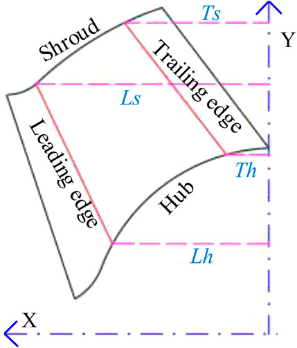
FIGURE 1. Meridional plane of the original model impeller.
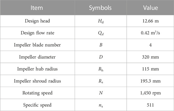
TABLE 1. Original model design parameters.
A calculation domain (Figure 2), consisting of four components—the output elbow, diffuser, impeller and inlet pipe—was constructed to ensure that the numerical simulation accurately reflects the experimental condition. To improve the computational convergence and accuracy, structured meshes with O-type topology were used to mesh the outlet elbow and inlet pipe in ANSYS-ICEM, and hexahedral structured meshes with H/C-type and O-type topologies were used to mesh the impeller and diffuser in ANSYS-Turbogrid. For the same purpose, all the meshes near the walls were refined.
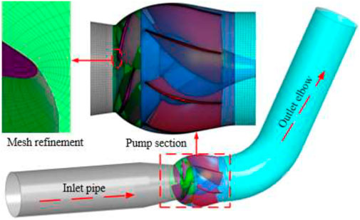
FIGURE 2. Mesh division.
The mesh-independence analysis results are presented in Table 2. When the number of grids is greater than 4.6 million, the calculated values of head and efficiency almost not change with the number of grids. Therefore, after taking into account the cost and accuracy of the calculation, scheme 3 was adopted for meshing the computational domain in this study, and the maximum Y+ near the wall is 46.

TABLE 2. Mesh-independence analysis results.
The commercial software ANSYS-CFX was employed in this study to perform the full-channel numerical simulation of mixed-flow pumps with the help of k–ω shear stress transport turbulence model. “Opening” and “Mass flow rate” were employed in the outlet and inlet, respectively. The interface between the rotating and fixing parts is “Frozen rotor”. The convective term was discretized by “High resolution”. “Automatic wall function” and “No slip wall” were employed for all walls (Menter, 1994; Menter et al., 2003; Hieninger et al., 2021). The number of iterative steps was set to 1,000 and the convergence criterion was set to 10−5.
A closed test stands at Jiangsu University (Figure 3) with comprehensive uncertainty of 0.28% was used to test the performance of the original model to check the numerical simulation accuracy. The following is the description of the main equipments and their accuracy: EJA intelligent differential pressure transmitters with 0.1% accuracy, JCL1 intelligent torque-speed sensor with 0.1% accuracy, OPTIFLUX 2000F intelligent electromagnetic flowmeter with 0.2% accuracy, CY200 pressure sensors with 0.1% accuracy.
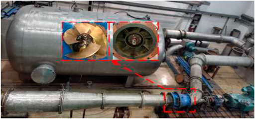
FIGURE 3. Test bench.
Figure 4 gives the comparison of the original model prediction results with the experimental results. The predicted performance can be seen highly consistent with the experimental performance in the range of 0.5Qdes to 1.3Qdes, and the largest error between them does not exceed 2.5%. Hence, it can be considered that the numerical simulation has adequate precision to guarantee the credibility of this study.
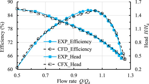
FIGURE 4. Comparison between experimental and predicted performance.
The proved circulation method based on the inviscid assumption was adopted to parameterize the blade (Zangeneh et al., 1998). To save space, only a brief description of the core computation was given here; for more details, please refer to the original literature (Zangeneh, 1991). In flow field calculation, velocity was divided into circumferential average and periodic velocity, which can be calculated by the following equations.
where
The blade shape was calculated by Eq. 3
where
From the control equation, it is clear that the parameter
where
Therefore, to facilitate the blade pressure control, blade loading (
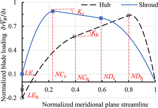
FIGURE 5. Hydrodynamic parameters definition schematic.
To make the optimized mixed-flow pump have better energy characteristics and similar head, the head and efficiency at 1.0Qdes were taken as the constraint and optimization target in this study.
The hub ratio was maintained during the optimization process to provide a better match between the diffuser and the optimized impeller (Wang et al., 2021b). Thus, in the parameterization of the impeller, the geometric parameters Lh, Ls, Th and Ts shown in Figure 1 were used for the parametrization of the meridional plane, and the hydrodynamic parameters LEh, NCh, NDh, Kh, LEs, NCs, NDs and Ks shown in Figure 5 were used for the blade parametrization. Zhu et al. (2018) indicated that the inclination angle at blade trailing edge (ST) has a large influence on the calculation results of the circulation method; therefore, ST was also selected as a test factor in this study. To facilitate the subsequent range analysis, the level of each factor was set to 3, as shown in Table 3.
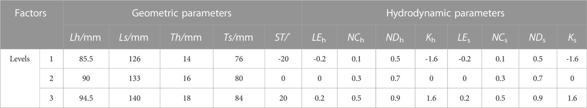
TABLE 3. Relationship between the test factors true value and level.
Taguchi method (Yang et al., 2021; Bai et al., 2022) has the advantages of reasonable experimental arrangement, short cycle and low cost, making it wise to be used for the experimental scheme construction in this study. From the above analysis, the number of factors and their levels were 13 and 3 respectively, therefore, the L27 (313) standard orthogonal table was employed for the construction of the experimental scheme, and a total of 27 different schemes were created.
Table 4 is the factors and targets of each scheme. In contrast to the original model efficiency (85.31%) and head (12.42 m), there were 21 schemes with improved efficiency, 16 schemes with the required head, and 15 schemes with both head and efficiency. Furthermore, scheme 4 has the highest head of 13.38 m, while scheme 3 has the highest efficiency of 87.96%.
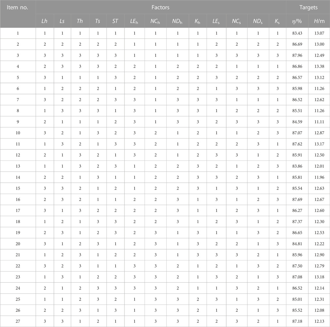
TABLE 4. Experimental scheme and calculation results.
The influence order of factors on the target, and the trend of the target with the level of factors is defined by extreme analysis (Ahmad and Prakash, 2021). The range R* was calculated by the following equations:
where
Table 5 is the efficiency and head range analysis results. The effect order of factors on efficiency is Ls, Kh, Lh, LEh, LEs, ST, NDs, NCh, Ts, NCs, Ks, Th and NDh, while the effect order of factors on head is NDh, Kh, NCs, ST, Ks, NDs, LEs, Ts, Ls, Lh, NCh, LEh and Th. Therefore, both hydrodynamic and geometric parameters should be considered simultaneously in the mixed-flow pump optimization design to maximize the energy characteristics improvement, since both of them have a large influence on the efficiency. To show the trend of the target with the level of factors more intuitively, geometric and hydrodynamic parameters’ main effects on the target were plotted in Figure 6 according to Table 5.
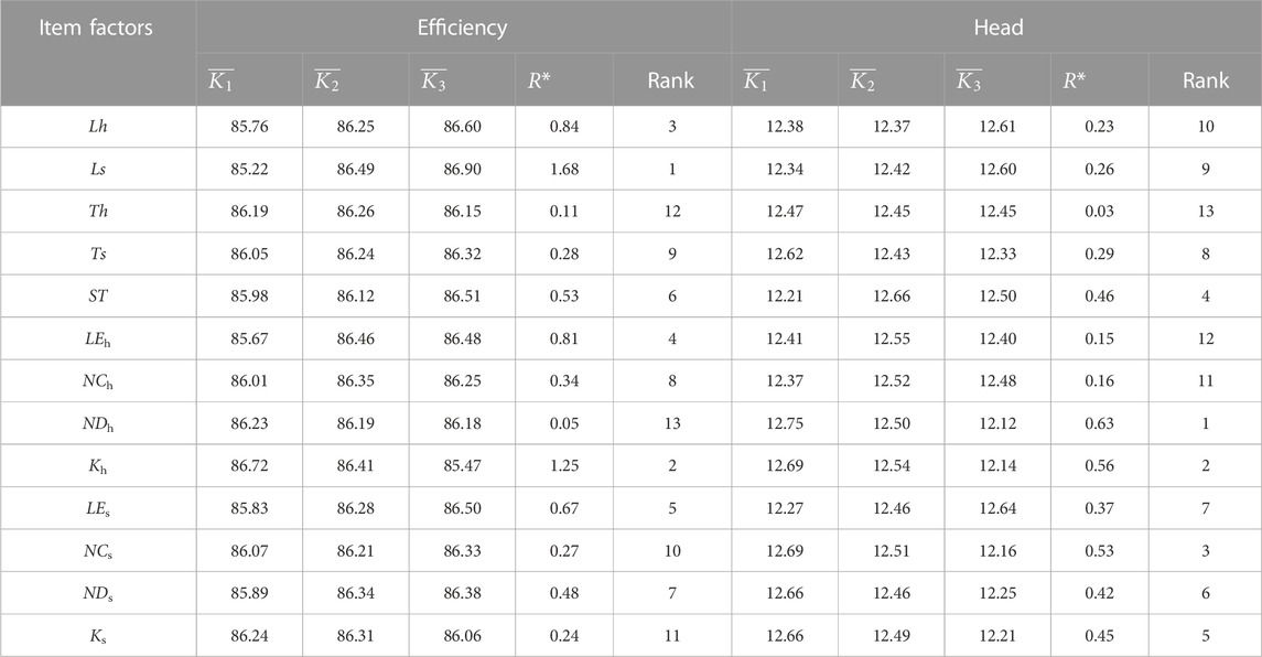
TABLE 5. Range analysis results.

FIGURE 6. Main effect of hydrodynamic and geometric parameters on the objectives: (A) Efficiency; (B) Head.
To obtain the response relationship between the factors and the objectives, the data in Table 4 were subjected to a regression analysis of variance (Chiranjeevi et al., 2022). It is generally accepted that the correlation between the test factors and the optimization objectives is statistically significant when the p-value is less than 0.05. Therefore, according to the results of variance analysis in Table 6, parameters Ls, Kh, Lh, LEh and LEs were significant factors for efficiency, and parameters NDh, Kh, NCs, Ks, NDs and LEs were significant factors for head. The results of the p-value analysis once again show that both the geometric and hydrodynamic parameters have significant influence on the mixed-flow pump energy characteristics. Equation 8 and Equation 9 are the efficiency and head regression equations, respectively.
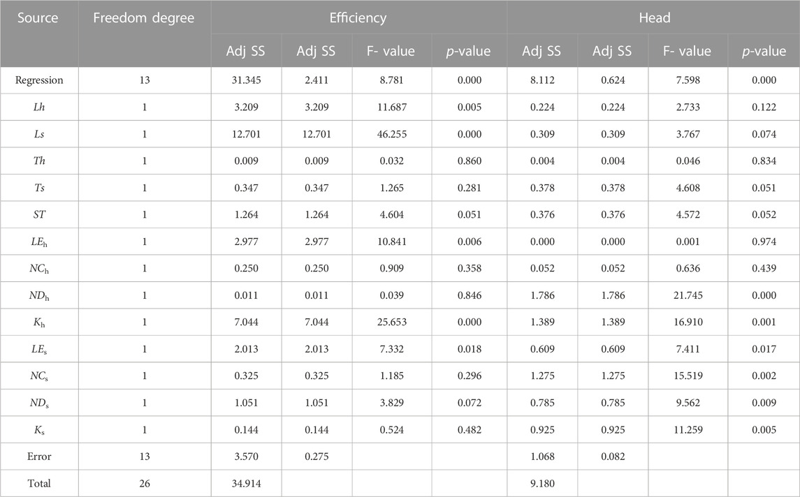
TABLE 6. Results of the variance regression analysis.
To make the optimized mixed-flow pump with better energy characteristics and suitable head, the levels of the test factors Lh, Ls, Th, Ts, ST, LEh, NCh, NDh, Kh, LEs, NCs, NDs and Ks were set to 3, 3, 2, 3, 3, 3, 2, 1, 1, 3, 3, 3 and 2, respectively, based on the results of the range and regression analyses.
Figure 7 shows the impeller shape comparison between the original and optimized model. Compared to the original model the optimized model has an increased overflow area at the hub and a reduced overflow area at the shroud. In addition, the optimized model blade trailing edge inclination angle is also increased. Figure 8 is the energy characteristics comparison between the optimized and original model. The optimized model efficiency and head at design condition are 88.51% and 12.43 m respectively, representing a 3.2% increase in efficiency and almost no change in head. The improved efficiency and nearly unchanged head indicate that the geometric and hydrodynamic parameters adopted in this study are reasonable.
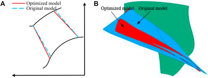
FIGURE 7. Comparison of original and optimized model impeller shapes: (A) Meridional plane; (B) blade shape.
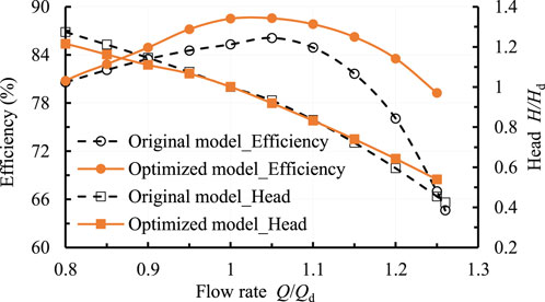
FIGURE 8. Comparison of original and optimized model energy characteristic.
To elucidate the optimization mechanism, the energy loss of the optimized model was comparatively analyzed with that of the original model using entropy production theory. Similarly, only a brief introduction to the main computational equations of entropy production theory was given here; for more details, please refer to the original literature (Kock and Herwing, 2004; Qi et al., 2022).
For turbulent flow of viscous fluids, the entropy is largely induced by viscous dissipation, turbulent kinetic energy dissipation and wall effects, and are respectively calculated using the following equations.
where
where
The comparison of different types of entropy production distributions for the optimized and original models can be found in Figure 9. The total entropy production of the optimized model was significantly reduced in comparison to the original model, especially in the impeller, diffuser and outlet pipe, where total entropy production was reduced by 104.31, 389.66 and 308.61 W, respectively. When specific to the different types of entropy production, the variation of total entropy production in the impeller was mainly caused by both indirect and wall entropy production, while the variation of total entropy production in the diffuser and outlet pipe was mainly induced by indirect entropy production.
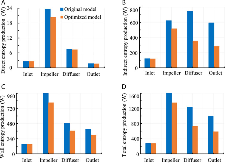
FIGURE 9. Comparison of different types of entropy production distribution: (A)
To better clarify how the mixed flow pump’s energy loss characteristics are affected by internal flow patterns, the energy dissipation caused by the fluid motion was defined as the fluid entropy production rate (FEPR), whose value is equal to the sum of the direct and indirect entropy production rate.
The distribution of FEPR for the optimized and original models at impeller different spans is shown in Figure 10. The optimized and original model mid-span FEPR distribution was basically the same, and a larger FEPR caused by the jet-wake (Wu et al., 2021) was observed at blade trailing edge. However, compared to the original model, the FEPR in the optimized model shroud was markedly decreased, especially near the pressure surface. Also, near the hub of the impeller, the FEPR of the optimized model at the blade trailing edge was markedly decreased compared to the original model.
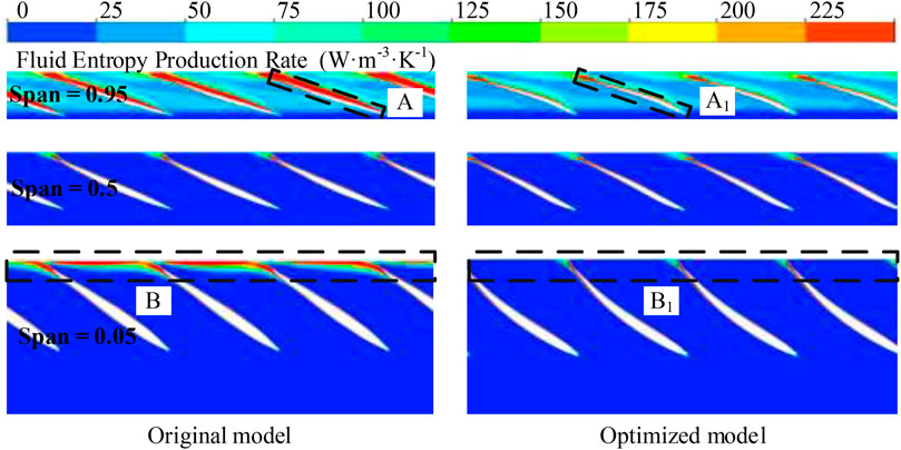
FIGURE 10. Impeller FEPR distribution comparison.
Although the diffuser is the same for the optimized and original models, the FEPR distribution in the two diffusers is quite different due to the difference of impeller outlet flow regime. Figures 11, 12 are the impeller outlet axial velocity distribution and diffuser different spans FEPR distribution respectively. The axial velocity at the outlet of the original model impeller increases progressively from the hub to shroud, and backflow was generated in a small region near the hub due to the boundary layer detachment (Kim et al., 2020). Due to the adverse flow pattern at the outlet of the original model impeller, a large FEPR was produced near the hub at the inlet of the diffuser, as shown in region D of Figure 12. After optimization, the axial velocity at impeller outlet near the hub was significantly increased, which effectively prevents the boundary layer detachment caused by the accumulation of low-momentum fluid. Accordingly, the FEPR near the hub at the inlet of the diffuser is markedly reduced.
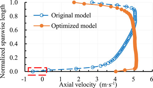
FIGURE 11. Impeller outlet axial velocity distribution comparison.
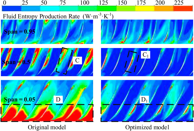
FIGURE 12. Diffuser FEPR distribution comparison.
A similar analysis was performed on the outlet pipe. Figure 13 is the distribution of the outflow angle
where V represent the velocity,
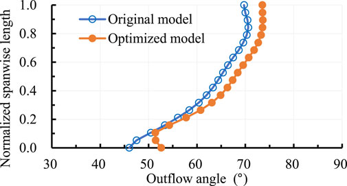
FIGURE 13. Diffuser outlet outflow angle distribution comparison.
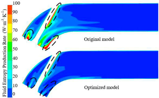
FIGURE 14. Outlet pipe FEPR distribution comparison.
In this work, a typical mixed-flow pump was numerically simulated and experimentally verified. Then, its impeller was parameterized by five geometric and eight hydrodynamic parameters and optimized using the Taguchi method. Finally, the main and minor order of the parameters were determined using range and regression analysis, and the optimization mechanism was revealed by the energy loss visualization technique. The following conclusions were drawn:
(1) The geometric parameters Ls and Lh, as well as the hydrodynamic parameters LEh, LEs and Kh have a great influence on the mixed-flow pump efficiency. To maximize the energy characteristics of the mixed-flow pump, both geometric and hydrodynamic parameters need to be considered in its optimization design.
(2) The efficiency and head of the optimized model at the design condition are 88.51% and 12.43 m respectively, which represents a 3.2% increase in efficiency and almost no change in head compared to the original model. The improved efficiency and nearly unchanged head indicate that the geometric and hydrodynamic parameters adopted in this study are reasonable.
(3) The reduction of energy loss in the impeller downstream components induced by the improved flow pattern at impeller outlet contributes more than 87% to the performance improvement. Therefore, in the optimization of mixed-flow pump impeller, not only the improvement of impeller energy characteristics should be concerned, but also the change of its outlet flow pattern.
The original contributions presented in the study are included in the article/supplementary material, further inquiries can be directed to the corresponding author.
JC: Writing–original draft, Software, Methodology. YB: Writing–review and editing. MW: Supervision, Guidance. HX: Supervision. XC: Data curation.
Author XC was employed by Anhui Ding Yuan Engineering Construction Co., HX was employed by Jiangsu Province Water Engineering Sci-tech Consulting Co.
The remaining author declares that the research was conducted in the absence of any commercial or financial relationships that could be construed as a potential conflict of interest.
All claims expressed in this article are solely those of the authors and do not necessarily represent those of their affiliated organizations, or those of the publisher, the editors and the reviewers. Any product that may be evaluated in this article, or claim that may be made by its manufacturer, is not guaranteed or endorsed by the publisher.
Ahmad, S., and Prakash, O. (2021). Optimization of ground heat exchanger of the ground source heat pump system based on exergetic analysis using Taguchi technique. P I Mech. Eng. C-J Mec. 235 (21), 5892–5901. doi:10.1177/0954406221991183
Bai, L., Yang, Y., Zhou, L., Li, Y., Xiao, Y., and Shi, W. (2022). Optimal design and performance improvement of an electric submersible pump impeller based on Taguchi approach. Energy 252, 124032. doi:10.1016/j.energy.2022.124032
Bing, H., Cao, S., Tan, L., and Zhu, B. (2013). Effects of meridional flow passage shape on hydraulic performance of mixed-flow pump impellers. Chin. J. Mech. Eng-en 26 (3), 469–475. doi:10.3901/cjme.2013.03.469
Bonaiuti, D., Zangeneh, M., Aartojarvi, R., and Eriksson, J. (2010). Parametric design of a waterjet pump by means of inverse design, CFD calculations and experimental analyses. J. Fluid Eng-T Asme 132 (3), 031104. doi:10.1115/1.4001005
Bonaiuti, D., and Zangeneh, M. (2009). On the coupling of inverse design and optimization techniques for the multiobjective, multipoint design of turbomachinery blades. J. Turbomach. 131 (2), 021014. doi:10.1115/1.2950065
Chiranjeevi, P., Ashok, V., Srinivasan, K., and Sundararajan, T. (2022). Performance analysis of single-phase space thermal radiators and optimization through taguchi-neuro-genetic approach. J. Therm. Sci. Eng. Appl. 14 (6), 061012. doi:10.1115/1.4052897
Fallah-Ardeshir, H., Ehghaghi, B., and Nill-Ahmadabadi, M. (2020). Inverse design of a centrifugal pump on the meridional plane using ball-spine algorithm. Sci. Iran. 27 (5), 2478–2488.
Goto, A., Takemura, T., and Zangeneh, M. (1996). Suppression of secondary flows in a mixed-flow pump impeller by application of three-dimensional inverse design method: Part 2-experimental validation. J. Turbomach. 118 (3), 544–551. doi:10.1115/1.2836701
Gu, Y., Cheng, J., Wang, P., Cheng, L., Si, Q., Wang, C., et al. (2022). A flow model for side chambers of centrifugal pumps considering radial wall shear stress. P I Mech. Eng. C-J Mec. 236 (13), 7115–7126. doi:10.1177/09544062211073023
Gu, Y., Li, J., Wang, P., Cheng, L., Qiu, Y., Wang, C., et al. (2022). An Improved one-dimensional flow model for side chambers of centrifugal pumps considering the blade slip factor. J. Fluid Eng-T Asme 144 (9), 091207. doi:10.1115/1.4054138
Hawthorne, W., Wang, C., and McCune, J. (1984). Theory of blade design for large deflections: Part I-two-dimensional cascade. J. Eng. Gas. Turb Power 106 (2), 346–353. doi:10.1115/1.3239571
Hieninger, T., Schmidt-Vollus, R., and Schlucker, E. (2021). Improving energy efficiency of individual centrifugal pump systems using model-free and on-line optimization methods. Appl. Energ 304, 117311. doi:10.1016/j.apenergy.2021.117311
Huang, R., Luo, X., Ji, B., Wang, P., Yu, A., Zhai, Z., et al. (2015). Multi-objective optimization of a mixed-flow pump impeller using modified NSGA-II algorithm. Sci. China Technol. S. C. 58 (12), 2122–2130. doi:10.1007/s11431-015-5865-5
Kim, S., Kim, Y., Kim, J., and Choi, Y. (2020). Design optimization for mixed-flow pump impeller by improved suction performance and efficiency with variables of specific speeds. J. Mech. Sci. Technol. 34 (6), 2377–2389. doi:10.1007/s12206-020-0515-7
Kim, S., Kim, Y., Kim, J., and Choi, Y. (2019). Three-objective optimization of a mixed-flow pump impeller for improved suction performance and efficiency. Adv. Mech. Eng. 11 (12), 168781401989896. doi:10.1177/1687814019898969
Kock, F., and Herwing, H. (2004). Local entropy production in turbulent shear flows: A high-Reynolds number model with wall functions. Int. J. Heat. Mass Tran 47 (10), 2205–2215. doi:10.1016/j.ijheatmasstransfer.2003.11.025
Lee, K., Choi, Y., Kim, Y., and Yun, J. (2008). Design of axial fan using inverse design method. J. Mech. Sci. Technol. 22 (10), 1883–1888. doi:10.1007/s12206-008-0727-8
Leguizamon, S., and Avellan, F. (2020). Open-Source implementation and validation of a 3D inverse design method for Francis turbine runners. Energies 13 (8), 2020. doi:10.3390/en13082020
Liang, J., Lu, L., Xu, L., Chen, W., and Wang, G. (2012). Influence of flow velocity circulation at guide vane outlet of axial-flow pump on hydraulic loss in outlet condition. CSAE 28 (01), 55–60.
Lu, Y., Wang, X., Wang, W., and Zhou, F. (2018). Application of the modified inverse design method in the optimization of the runner blade of a mixed-flow pump. Chin. J. Mech. Eng-en 31 (1), 105. doi:10.1186/s10033-018-0302-x
Ma, Z., Zhu, B., Rao, C., and Shangguan, Y. (2019). Comprehensive hydraulic improvement and parametric analysis of a Francis turbine runner. Energies 12 (2), 307. doi:10.3390/en12020307
Menter, F., Ferreira, J., and Esch, T. (2003). The SST turbulence model with improved wall treatment for heat transfer predictions in gas turbines. Tokyo, Japan: International Gas Turbine Congress.
Menter, F. (1994). Two-equation eddy-viscosity turbulence models for engineering applications. AIAA J. 32 (8), 1598–1605. doi:10.2514/3.12149
Nahon, J., Zangeneh, M., Nohmi, M., Watanabe, H., and Goto, A. (2021). A robust inverse design solver for controlling the potential aggressiveness of cavitating flow on hydrofoil cascades. Int. J. Numer. Meth Fl 93 (7), 2291–2310. doi:10.1002/fld.4974
Pei, J., Wang, W., and Yuan, S. (2016). Multi-point optimization on meridional shape of a centrifugal pump impeller for performance improvement. J. Mech. Sci. Technol. 30 (11), 4949–4960. doi:10.1007/s12206-016-1015-7
Qi, B., Zhang, D., Geng, L., Zhao, R., and Van Esch., (2022). Numerical and experimental investigations on inflow loss in the energy recovery turbines with back-curved and front-curved impeller based on the entropy generation theory. Energy 239 (E), 122426. doi:10.1016/j.energy.2021.122426
Shim, H., Kim, K., and Choi, Y. (2018). Three-objective optimization of a centrifugal pump to reduce flow recirculation and cavitation. J. Fluid Eng-T Asme 140 (9), 091202. doi:10.1115/1.4039511
Si, Q., Lu, R., Shen, C., Xia, S., Sheng, G., and Yuan, J. (2020). An intelligent CFD-based optimization system for fluid machinery: Automotive electronic pump case application. Appl. Sci-basel 10 (1), 366. doi:10.3390/app10010366
Suh, J., Yang, H., Kim, Y., Lee, K., Kim, J., Joo, W., et al. (2019). Multi-objective optimization of a high efficiency and suction performance for mixed-flow pump impeller. Eng. Appl. Comp. Fluid 13 (1), 744–762. doi:10.1080/19942060.2019.1643408
Wang, M., Li, Y., Yuan, J., and Osman, F. (2021). Influence of spanwise distribution of impeller exit circulation on optimization results of mixed flow pump. Appl. Sci-basel 11 (2), 507. doi:10.3390/app11020507
Wang, M., Li, Y., Yuan, J., and Osman, F. (2021). Matching optimization of a mixed flow pump impeller and diffuser based on the inverse design method. Processes 9 (2), 260. doi:10.3390/pr9020260
Wang, M., Li, Y., Yuan, J., and Yuan, S. (2022). Effects of different vortex designs on optimization results of mixed-flow pump. Eng. Appl. Comp. Fluid 16 (1), 36–57. doi:10.1080/19942060.2021.2006091
Wu, C., Li, Q., Zheng, F., Wu, P., Yang, S., Ye, H., et al. (2021). Improve of unsteady pressure pulsation based on jet-wake suppression for a low specific centrifugal pump. J. Fluid Eng-T Asme 143 (11), 111202. doi:10.1115/1.4051402
Yang, W., Lei, X., Zhang, Z., Li, H., and Wang, F. (2017). Hydraulic design of submersible axial-flow pump based on blade loading distributions. CSAM 48 (11), 179–187.
Yang, W., and Xiao, R. F. (2014). Multiobjective optimization design of a pump-turbine impeller based on an inverse design using a combination optimization strategy. J. Fluid Eng-T Asme 136 (1), 014501. doi:10.1115/1.4025454
Yang, Y., Zhou, L., Hang, J., Du, D., Shi, W., and He, Z. (2021). Energy characteristics and optimal design of diffuser meridian in an electrical submersible pump. Renew. Energ 167, 718–727. doi:10.1016/j.renene.2020.11.143
Yin, J., and Wang, D. (2014). Review on applications of 3D inverse design method for pump. Chin. J. Mech. Eng-en 27 (3), 520–527. doi:10.3901/cjme.2014.03.520
Zangeneh, M. (1991). A compressible three-dimensional design method for radial and mixed flow turbomachinery blades. Int. J. Numer. Meth Fl 13, 599–624. doi:10.1002/fld.1650130505
Zangeneh, M., Gota, A., and Takemura, T. (1996). Suppression of secondary flows in a mixed-flow pump impeller by application of three-dimensional inverse design method: Part 1-design and numerical validation. J. Turbomach. 118 (3), 536–543. doi:10.1115/1.2836700
Zangeneh, M., Goto, A., and Harada, H. (1998). On the design criteria for suppression of secondary flows in centrifugal and mixed flow impellers. J. Turbomach. 120 (4), 723–735. doi:10.1115/1.2841783
Zhang, R., and Zhao, X. (2020). Inverse method of centrifugal pump blade based on Gaussian process regression. Math. Probl. Eng. 2020, 1–10. doi:10.1155/2020/4605625
Keywords: pump, coupling optimization, circulation method, geometric and hydrodynamic parameters, numerical simulation
Citation: Chen J, Wang M, Bao Y, Chen X and Xia H (2023) Mixed-flow pump performance improvement based on circulation method. Front. Energy Res. 11:1177437. doi: 10.3389/fenrg.2023.1177437
Received: 01 March 2023; Accepted: 22 March 2023;
Published: 06 April 2023.
Edited by:
Yongfei Yang, Nantong University, ChinaReviewed by:
Bing Qi, Lanzhou University of Technology, ChinaCopyright © 2023 Chen, Wang, Bao, Chen and Xia. This is an open-access article distributed under the terms of the Creative Commons Attribution License (CC BY). The use, distribution or reproduction in other forums is permitted, provided the original author(s) and the copyright owner(s) are credited and that the original publication in this journal is cited, in accordance with accepted academic practice. No use, distribution or reproduction is permitted which does not comply with these terms.
*Correspondence: Mengcheng Wang, amR3bWMyMDE4QDE2My5jb20=
Disclaimer: All claims expressed in this article are solely those of the authors and do not necessarily represent those of their affiliated organizations, or those of the publisher, the editors and the reviewers. Any product that may be evaluated in this article or claim that may be made by its manufacturer is not guaranteed or endorsed by the publisher.
Research integrity at Frontiers
Learn more about the work of our research integrity team to safeguard the quality of each article we publish.