 Ke Cheng1
 Ting Jiang
 Yajing He
94% of researchers rate our articles as excellent or good
Learn more about the work of our research integrity team to safeguard the quality of each article we publish.
Find out more
ORIGINAL RESEARCH article
Front. Energy Res., 17 March 2023
Sec. Process and Energy Systems Engineering
Volume 11 - 2023 | https://doi.org/10.3389/fenrg.2023.1170123
This article is part of the Research TopicOptimal Design and Efficiency Improvement of Fluid Machinery and SystemsView all 18 articles
Canned Motor Pump (CMP) is widely used in petroleum, chemical, electric power, aerospace engineering, and military manufacturing industries due to its good sealing performance. In the structure of canned motor pump, the rotor of the motor and the impeller of the pump are fixed on the same shaft. Therefore, balancing the axial force and the radical force of the rotor is a key task for its reliable operation. The numerical simulation study of CMP is carried out in this paper, aiming to improve the pump efficiency and balance the axial force and radial force. The internal flow and rotor force characteristics of CMP under different radial clearances of front or back wear-rings and different volute partitions are studied. The results show that with the increase of wear-ring gap, external performances decline, and the front wear-ring gap contributed the largest influence. Under the working conditions of 0.6QBEP and 0.8QBEP, front wear-rings contributed the largest influence to axial force, and the degree of influence decreases with the rate of flow increase. Radial clearances of front or back wear-rings have less impact on the radial force of the impeller. Adding clapboard for volute has a greater impact on the value and direction of radial force, and it can promote the balance of radial force. However, the effectiveness value will decrease. The research in this paper can provide theoretical basis and reference for performance prediction and hydraulic optimization of CMP.
As general machinery, centrifugal pumps are widely used in aerospace, navigation, petrochemical, refrigeration, medical, environmental protection, agricultural irrigation and other fields (Rzentkowski and Zbroja, 2000; Cdina, 2003; Choi et al., 2003; Alfayez et al., 2005). However, when centrifugal pumps are used for medium transfer or pressurization, due to the characteristics of the medium, such as flammable, explosive, volatile, corrosive, and highly toxic, its tightness and reliability often failed to reach the standard. The canned motor pump does not have the shaft sealing device of the traditional centrifugal pump, which makes it leak-free. It is suitable for transporting valuable or radioactive media. Canned motor pump is widely used for medium transfer as its advantages of no leakage, small size and high reliability (Author Anonymous, 1996; Zhu et al., 2020). In the design, manufacture and operation of canned motor pump, axial and radial forces are one of important factors that must be considered (Zhou and Wang, 2016; Arndt et al., 1989; ye Jin et al., 2022; Qianyan et al., 2018). If axial and radial forces are not reduced, the rotor shaft will be deflected by alternating stresses during operation. So that the bearing rotor shielding sleeve and even impeller motor cause serious damage (Launder and Spalding, 1974; Author Anonymous, 2019; Jin et al., 2022a). At the same time, the canned motor pump is not easy to disassemble and later maintenance is difficult. Therefore, in the early design, the accuracy of the shaft and radial forces calculation will directly affect the safety and reliability of the unit (Wang et al., 2001; Zhu and Kamemoto, 2005).
At present, the research on canned motor pump mainly includes theoretical analysis, experimental study, empirical analysis and numerical study (Arndt et al., 1990; Dawes, 1994; Qin and Tsukamoto, 1997; Guan et al., 2020a; Guan et al., 2020b; Hongyu et al., 2021; Song et al., 2021). Cabrera et al. (2005) experimentally measured the magnitude of the radial force on the impeller of canned motor pump. And also carried out theoretical research on the force characteristics at both ends of the canned motor pump bearing by means of calculation simulation software. Gertzos et al. (2008) used the Bingham fluid model in the FLUENT software to perform a three-dimensional numerical calculation of the canned motor pump bearing ends, analyzed the influence of different bearing width-diameter ratios on the pressure distribution of the liquid film and studied the load carrying capacity and cooling performance of the motor bearing end. Friedrich et al. (Benra et al., 2006) carried out bi-directional fluid-structure coupling calculation on the vibration of a single canned motor pump blade, and obtained the influence of static pressure distribution on the pump blade under fluid transient state. The calculated results were compared with the experimental results, which proved that the bi-directional fluid-structure coupling calculation results were more consistent with the experimental values. Fortes et al. (Hirsch, 1988; Qu et al., 2010) calculated the transient pressure fluctuation in canned motor pump by using the periodic boundary condition of the overlapping network and phase lag. Koji Ikuta et al. (Jameson et al., 1981; Koji, 1991; Rasmussen et al., 2005) of Japan also proposed the application of contactless permanent magnet shielded pump in non-industrial fields. The research on the unsteady flow field characteristics of the impeller end of the canned pump and the force characteristics of the rotor at medium and high specific speeds is still relatively small at home and abroad, and some calculation formulas are quite different, which makes it difficult to follow. At present, the research papers on canned motor pump in international journals mainly focus on bearing cooling circuit, fluid-structure coupling calculation, etc. At the same time, a new canned motor pump with special structure and special purpose is also studied.
The research on the unsteady flow field at the impeller end and the rotor force characteristics of canned motor pump at medium and high specific speed is still less at home and abroad, and some calculation formulas are quite different, which makes it difficult for people to adapt to it (Jin et al., 2022b). Therefore, it is not only extremely important to study the accurate calculation and balance method of axial and radial forces of canned motor pump at medium and high specific speed, but also of great practical significance to the safety production of enterprises.
During the operation of canned motor pump, the internal flow is a complex three-dimensional unsteady turbulent flow. Up to now, the understanding of the fluid flow characteristics in the rotor components of the canned motor pump at medium and high specific speeds is not clear enough in engineering, especially the research on the leakage flow characteristics under the clearance between the front and rear rings of the canned motor pump is lacking. This paper takes the analysis of the details of the clearance flow and studies the influence of the clearance and the volute diaphragm on the external characteristics, internal flow field, and rotor force of the canned motor pump.
In this study, the transport medium of the canned motor pump is water, without considering compressibility, and the influence of gravity is weak. In the inertial coordinate system, the Naiver-Stokes equation can be written as:
where the
For the canned motor pump in this paper, the internal flow of its impeller is three-dimensional viscous incompressible unsteady flow. The continuity equation and the momentum equation are shown as follows:
Where:
There are significant differences between temporal and spatial characteristic scales in turbulent flow, and there are still many difficulties in solving the N-S equations directly to study the actual flow problems. Moreover, in engineering projects, the average flow on the time scale of turbulent flow is often considered, and in current engineering applications, the Reynolds time-averaged equation is usually used to simulate the canned motor pump. The Reynolds-averaged equation is expressed as follows:
where the
Incompressible and without considering the volume force, Eq. 2-7 is changed into the following equation for steady calculation.
Because of the characteristics of governing equations and turbulent flow in the canned motor pump, Reynolds time-averaged equations are used to analyze the internal flow field of canned motor pump.
Model HP300-175E/62 (3) canned motor pump is taken as the research object in this study. The design parameters are as follows, the flow rate is Q = 300 m3/h, the design head is H = 18.8m, the rotational speed is n = 1,500 r/min, and the specific is speed ns = 175. The system pressure is less than 0.6MPa, and the temperature of the conveying medium is less than 40 °C. The main geometric dimensions are shown in Table 1.
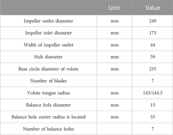
TABLE 1. Geometric dimensions of the CMP.
The 3D model of the canned motor pump is established by the Pro/E software (As shown in Figure 1A). The calculation domain consists of impeller, volute, front pump chamber, back pump chamber, inlet pipe, and outlet pipe. The model is meshed hexahedrally using ICEM. The tetrahedral unstructured grid is used for the water body at the impeller and volute, and the impeller surface and the volute tongue are densified to ensure the accuracy of the computation. The grid of each flow passage area is shown in Figure 1. For the small-size gap flow in the fluid domain of the front and rear pump chambers, the hexahedral structured grid is used in this paper to ensure that there are more grid layers to meet the calculation requirements when the gap thickness is small, as shown in Figure 2.
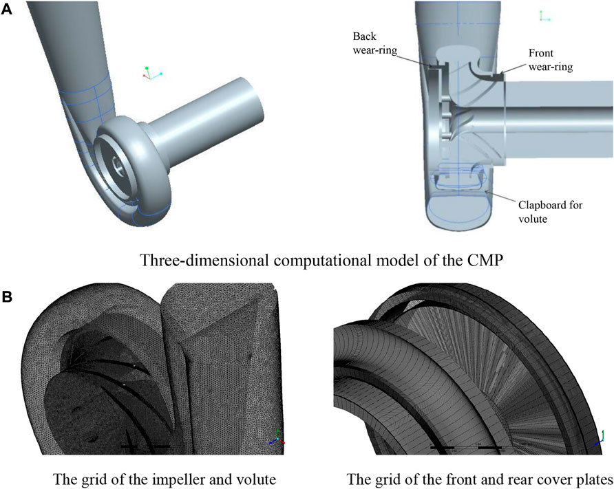
FIGURE 1. Three-dimensional computational model and grid of the CMP. (A) Three-dimensional computational model of the CMP. (B) The grid of the impeller and volute and the grid of the front and rear cover plates
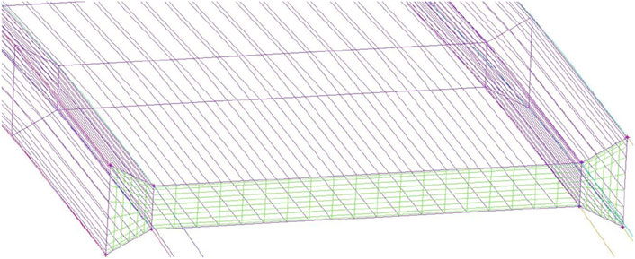
FIGURE 2. Mesh details at wear-ring.
The grid independence of the centrifugal pump is verified at a flow rate of 300 m3/h. In theory, the more the number of grid, the smaller the error caused by the grid. In this paper, five different mesh sizes are selected to simulate the internal flow of the model pump, and the simulation results are shown in Table 2. It can be seen that when the number of grids is greater than 4.78 million, with the increase of the number of grids, the head and efficiency values fluctuate slightly, which can be considered to meet the grid-independent conditions. Considering the calculation cost, the number of grids selected in the future calculation is 4.78 million.

TABLE 2. Grid independence analysis.
The front and back wear-rings have a great influence on the axial force balance of the canned motor pump, and the volute diaphragm has a great influence on the radial force balance of the canned motor pump. In order to study the influence of each component on the performance of the canned motor pump in detail, three groups of schemes are set up in this paper. The detailed information of each group is shown in Table 3. The b1 and b2 represent the unilateral radial clearance size of the front and rear rings respectively.
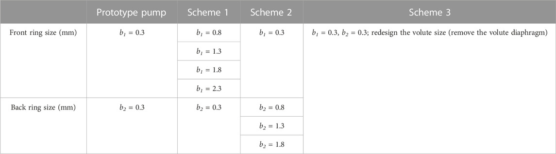
TABLE 3. Simulation grouping and related experimental scheme.
The ANSYS CFX software is chosen to simulate the internal flow of the canned motor pump. The RNG k-ε turbulence model has high accuracy in calculating high-speed flow and vortex flow, so it is used to analyze the internal flow field of the canned motor pump in this paper. The inlet boundary condition is set to total pressure inlet and medium turbulence (intensity = 5%). The mass flow outlet is adopted as the outlet boundary condition. All walls are set to have no-slip walls, and the standard wall function is used in the near-wall region. The convergence criterion is that the root means square is less than 10−5. In order to verify the numerical simulation results, external characteristics experiments were conducted on the CMP model. The comparison curve of numerical simulation results and test results are shown in Figure 3. It can be seen from the curves, the trend of the two basically agrees, and the computation error is within 4%. This indicates that the accuracy of the numerical computation is high and meets the research requirements.
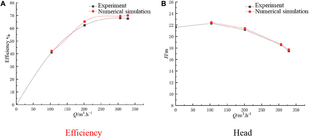
FIGURE 3. Comparison of hydraulic characteristics between numerical simulation and experiment. (A) Efficiency; (B) Head.
Figure 4 is the performance curve of the canned motor pump when the clearance of the front wear-ring is changed. It can be seen that the change of the clearance of the front wear-ring has a great influence on the external characteristics of the canned motor pump. The Q-H curve shows that the head decreases with the increase of flow. Under various working conditions, compared with the prototype pump head, with the increase of the clearance of the front wear-ring, the flow rate decreases regardless of its size. The Q-η curve shows that with the increase of flow rate, the efficiency value decreases first and then increases, and reaches the maximum value near the 1.0Q operating point. Compared with the efficiency of the prototype pump, the efficiency also decreases with the increase of the clearance of the front wear-ring under various working conditions. The efficiency decreases by 5% with the increase of the radial gap of 0.5 mm at 0.6Q and 1.4Q, and decreases by 10% at 1.0Q.
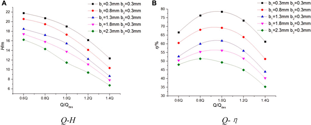
FIGURE 4. The performance curves of Scheme 1. (A) Q-H; (B) Q-η.
Figure 5 is the performance curve of the canned motor pump when the clearance of the back wear-ring is changed. It can be seen from the Fig that the change of the clearance of the back wear-ring has little effect on the external characteristics of the canned motor pump. Among them, with the increase of flow, the head will show a downward trend. Compared with the prototype pump, the head and efficiency under all working conditions show a downward trend with the increase of the clearance of the rear wear-ring. In addition, the impact of scheme 2 is less than that of scheme 1.
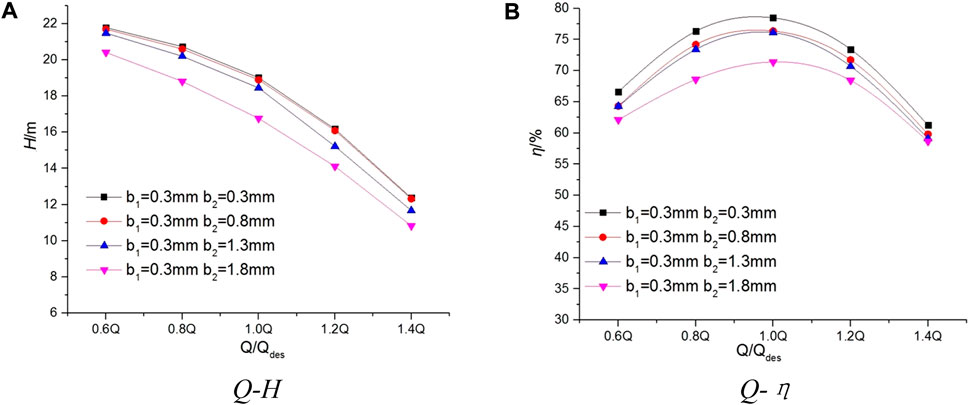
FIGURE 5. The performance curves of Scheme 2. (A) Q-H; (B) Q-η.
The internal flow fields of Scheme 1 and Scheme 2 under standard conditions are compared and analyzed in this section. For the convenience of observation, the X = 0 section is take n as the observation object. This section is located at the section position shown in Figure 1A.
Figure 6 shows the static pressure cloud image under different front wear-ring clearances in Scheme 1. As shown in Figure 6A, with the work done by the impeller, the static pressure of the water body increases significantly along the flow passage and reaches the maximum value at the outlet of the volute. With the increase of the clearance of the front wear-ring, the static pressure in the front cavity decreases significantly, while the static pressure in the rear cavity does not decrease significantly. The static pressure at the outlet of the front cavity increases to a certain extent, which affects the distribution of static pressure inside the whole impeller. At the same time, from the static pressure distribution in the figure, it is not difficult to find that with the increase of the radial clearance of the front wear-ring, the outlet pressure of the canned motor pump decreases significantly, and the head at the design operating point decreases. Traditionally, it is believed that the larger the clearance of the front wear-ring is, the easier it is to accumulate high-pressure and high-speed liquid in front of the impeller inlet, which reduces the necessary net positive suction head (NPSH) and improves the anti-cavitation ability of the canned motor pump.
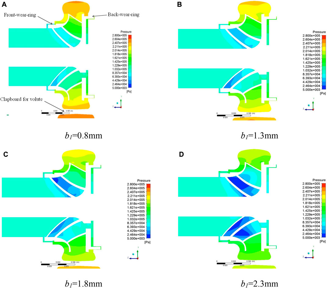
FIGURE 6. The static pressure distribution of X = 0 section under different clearance of front wear-ring. (A) b1 = 0.8 mm; (B) b1 = 1.3 mm; (C) b1 = 1.8 mm; (D) b1 = 2.3 mm.
Figure 7 shows the static pressure cloud image under different back ring clearances in Scheme 2. When the back ring clearance increases from 0.3 mm to 1.8 mm, the static pressure of the water in the front pump chamber and the impeller does not change significantly, while the static pressure of the water in the rear chamber increases slightly. At the same time, with the increase of the clearance of the rear ring, the leakage from the back pump chamber to the balance hole becomes larger, which affects the static pressure distribution at the back position of the shielding pump impeller.
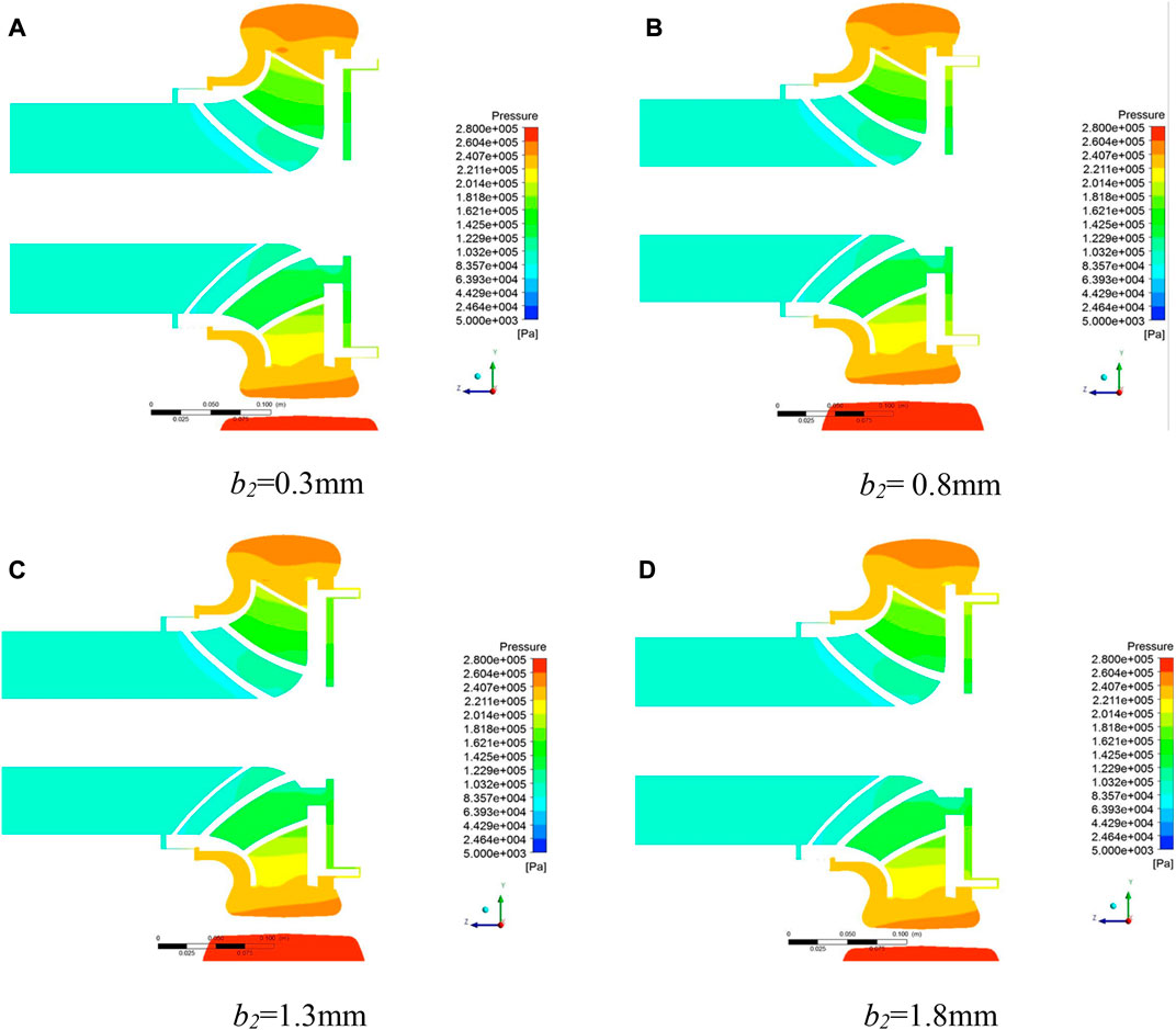
FIGURE 7. The static pressure distribution of X = 0 section under different clearance of back wear-ring. (A) b2 = 0.3 mm; (B) b2 = 0.8 mm; (C) b2 = 1.3 mm; (D) b2 = 1.8 mm.
Figure 8 is the absolute velocity cloud image under different front wear-ring clearances in Scheme 1. With the work done by the impeller, the absolute velocity increases significantly along the flow passage and reaches the maximum value at the impeller outlet. With the increase of the gap size of the front wear-ring of the canned motor pump, the flow velocity increases at the same time, the absolute velocity near the inlet of the impeller changes significantly, and the absolute velocity in the impeller increases significantly, which makes the velocity distribution in the impeller uneven and the flow stability worse.
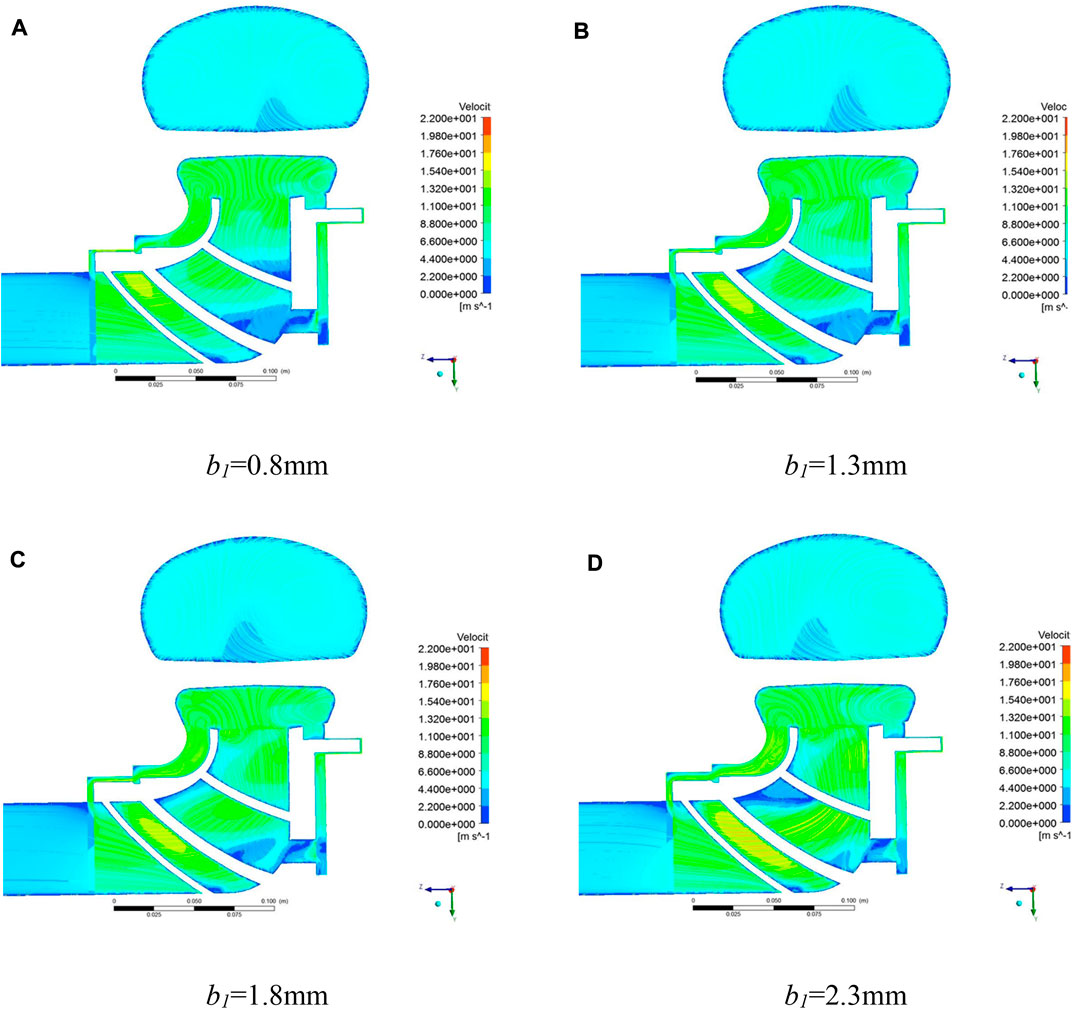
FIGURE 8. The absolute velocity distribution of X = 0 section under different clearance of front wear-ring. (A) b1 = 0.8 mm; (B) b1 = 1.3 mm; (C) b1 = 1.8 mm; (D) b1 = 2.3 mm.
Figure 9 is the absolute velocity cloud image under different back wear-ring clearances in Scheme 2. When the back wear-ring clearance changes (0.3 mm–1.8 mm), the absolute velocity of the water in the front pump cavity of the canned motor pump does not change much. When the gap of the rear ring is from 0.3 mm to 1.5 mm, the absolute velocity change is still not obvious. With the further increase of the ring leakage to 1.8 mm, the absolute velocity in the pump cavity behind the canned motor pump increases significantly. In addition, the change of the size of the rear mouth ring also affects the distribution of the velocity in the balance hole. When the clearance leakage decreases, the liquid flowing into the balance hole from the impeller outlet through the rear pump chamber decreases, and the vortex in the balance hole is obvious. With the increase of clearance leakage, the amount of liquid flowing into the balance hole from the rear pump chamber increases significantly, and there is no obvious vortex in the balance hole, which affects the velocity of main flow and the external characteristics of the canned motor pump.
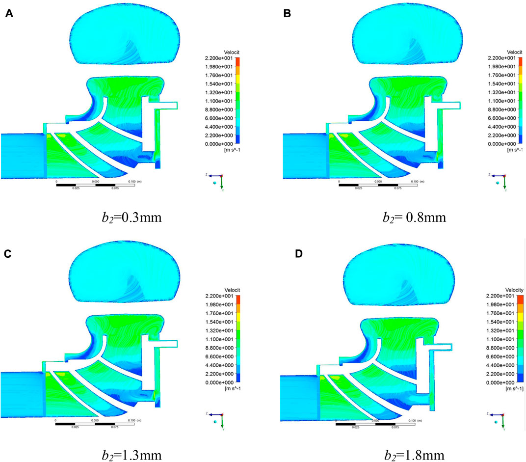
FIGURE 9. The absolute velocity distribution of X = 0 section under different clearance of back wear-ring. (A) b2 = 0.3 mm; (B) b2 = 0.8 mm; (C) b2 = 1.3 mm; (D) b2 = 1.8 mm.
Change the radial clearance value of the front and back wear-rings according to the previous scheme 1 and scheme 2, draw the following curve, and observe the change trend of the axial and radial forces. The positive direction of axial force is specified as the inlet direction of the impeller.
As shown in Figure 10, the size and direction of the axial force on the rotor components of the canned motor pump are determined by keeping the clearance of the rear ring unchanged and increasing the clearance of the front wear-ring. Under the standard working condition, the axial force increases with the increase of the front wear-ring clearance, and the axial force increases significantly when the front ring radial clearance increases from 0.3 mm to 2.3 mm, and the increment slows down from 2.3 to 10.3 mm. Under the condition of low flow rate (0.6Q), the axial force increases by 300 N when the clearance of the front orifice ring increases from 0.3 mm to 0.8 mm, and the direction does not change. With the further increase of the clearance of the front orifice ring, the axial force increases significantly. In the small flow range, the canned motor pump runs under the positive axial force, which affects the operation reliability of the canned motor pump. Under the condition of large flow rate (1.4Q), the direction of axial force changes from positive to negative, and the magnitude changes but is not obvious.

FIGURE 10. Axial force change of the CMP under different front wear-ring clearances.
As shown in Figure 11, keep the clearance of the front wear-ring unchanged and increase the clearance of the back wear-ring. In the whole flow range, the axial force decreases gradually with the increase of the clearance of the back wear-ring. Under the standard working condition, the axial force direction changes from positive to negative with the increase of the clearance of the ring, and its magnitude decreases first and then increases. Under the condition of small flow, the direction of axial force is not changed, and the magnitude of axial force decreases but not obviously, only decreases 50N at the point of 0.8 mm–1.3 mm. Under the overload condition, the axial force increases by 200N in the reverse direction when the clearance of the back wear-ring increases from 0.3 mm to 0.8 mm. And with the increase of the clearance of the rear grinding ring, the change is more obvious.
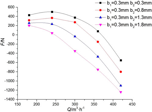
FIGURE 11. Axial force change of the CMP under different back wear-ring clearances.
Figures 12, 13 are the curves showing the change of the meridional force on the canned motor pump rotor with the working condition after changing the clearance between the front and back wear-rings. Through the comparison of the first and second schemes, it is found that the wear-rings of the front and back clearances has little effect on the radial force of the canned motor pump. Because the magnitude of the radial force is closely related to the absolute velocity of the impeller outlet, and the clearance of the wear-ring has little effect on the flow of the liquid in the impeller, and the absolute velocity of the impeller outlet changes little, so the change of the front and back wear-rings has little effect on the radial force on the impeller.
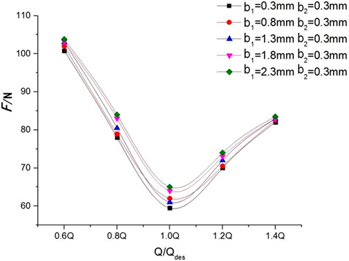
FIGURE 12. Radial force change of the CMP under different front wear-ring clearances.
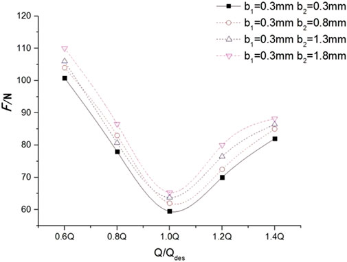
FIGURE 13. Radial force change of the CMP under different back wear-ring clearances.
As shown in Figure 14, there are two external characteristic curves of different volute forms under variable working conditions. It can be seen from the Q-H curve that when the flow rate is less than 0.6Q, the head of the prototype canned pump is higher than that of the third scheme, and with the increase of the flow rate, the head of the prototype canned pump decreases significantly, while the head curve in the third scheme is relatively flat as a whole, and the heads of the two models are basically close from 0.8Q to 1.0Q. The head value of the third scheme is greater than that of the prototype canned pump, and the difference is greater with the increase of flow. It can be seen from the Q-
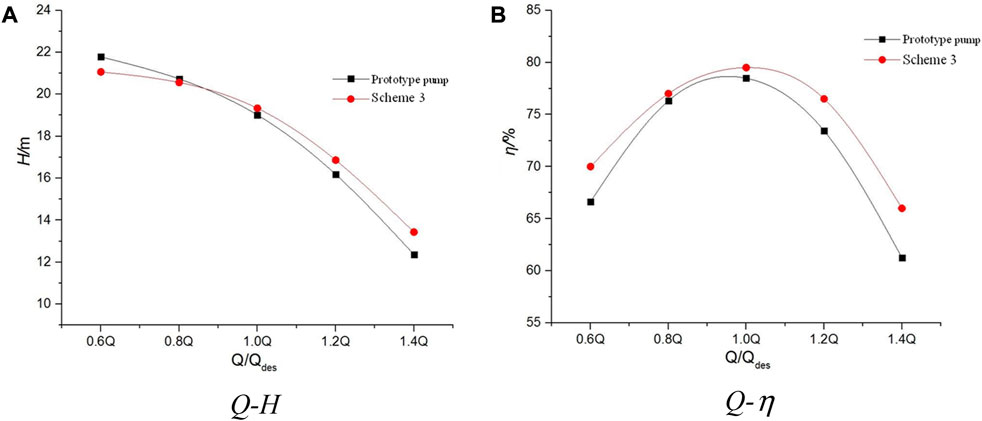
FIGURE 14. The performance curves of Scheme 3. (A) Q-H; (B) Q-η.
As shown in Figure 15, the static pressure distribution in the impeller flow passage of the third scheme is not much different from that of the prototype canned motor pump, and the pressure diffusion in the volute is obvious. It can be seen from Figures 16,17 that the liquid flow in the volute without the diaphragm in Scheme 3 is smooth, and there is no impact blocking between the liquid flow and the diaphragm, which reduces the energy loss of the water body and improves the head and efficiency compared with the prototype. In the prototype shell, although the liquid flow is blocked, the radial force of the impeller can be effectively balanced by the dynamic reaction force of the water on both sides of the baffle.
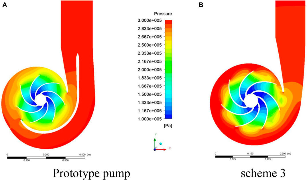
FIGURE 15. The static pressure distribution in the Z-axis direction under design conditions. (A) Prototype pump; (B) Scheme 3.
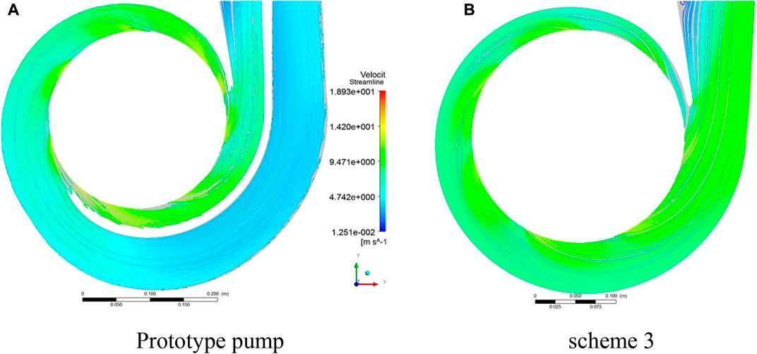
FIGURE 16. The absolute velocity distribution in the volute under design condition. (A) Prototype pump; (B) Scheme 3.
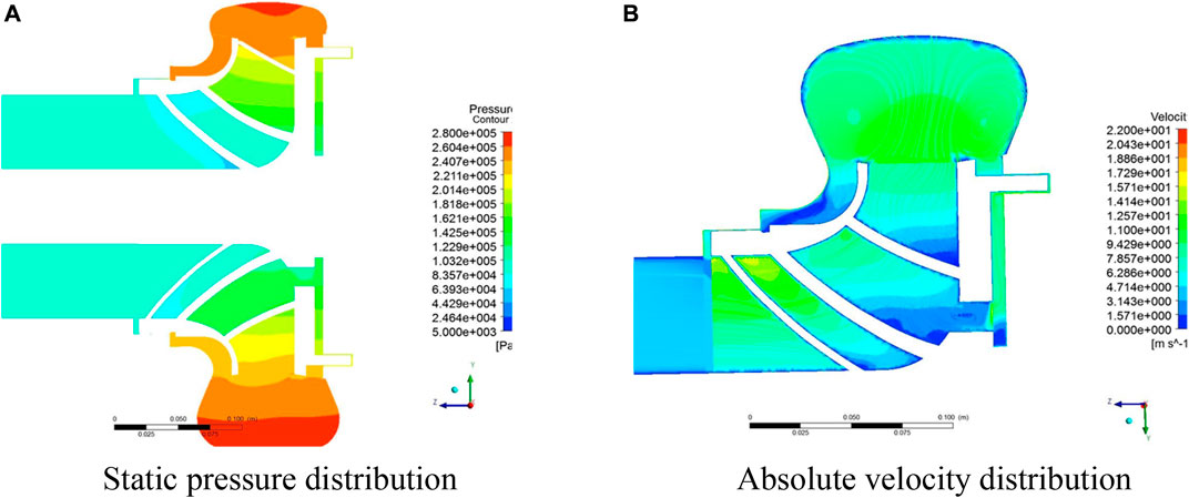
FIGURE 17. The static pressure and absolute velocity distribution on the X = 0 section in Scheme 3. (A) Static pressure distribution; (B) Absolute velocity distribution.
In order to analyze the influence of volute models with different structures on the axial and radial force of canned motor pump impeller, numerical analysis was carried out under five working conditions of 0.6Q, 0.8Q, 1.0Q, 1.2Q, and 1.4Q. Considering that the volute diaphragm is symmetrically distributed about the Z axis, the influence on the axial force is negligible. This section will mainly study the influence of the diaphragm on the magnitude and direction of the rotor radial force.
Figure 18 shows the magnitude and direction of the radial force of two types of volute under different working conditions. The X-axis direction in Figure 2 is set to 0°. It can be seen from Figure 18A that the radial force curve of the prototype pump is relatively flat with the change of flow, while the radial force in Scheme 3 decreases first and then increases with the increase of flow. In the whole flow range, the radial force in Scheme 3 is greater than that in the prototype pump, especially at the non-design operating point. In the vicinity of the design condition, the radial force (absolute value) on the impeller of the canned motor pump is the smallest.
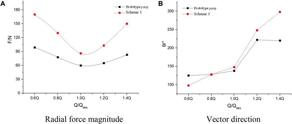
FIGURE 18. The magnitude and direction of radial force under different conditions. (A) Radial force magnitude; (B) Vector direction.
It can be seen from Figure 18B that in Scheme 3, with the increase of water flow in the canned motor pump, the angle value of the radial force on the impeller of the canned motor pump changes greatly; However, the direction vector of radial force on the impeller of double volute pump changes little from 0.6Q to 1.0Q and from 1.2Q to 1.4Q, and changes greatly from 1.0Q to 1.2Q. This is mainly due to the fact that when the actual flow is less than the design flow, the outflow velocity in the volute is small, resulting in a continuous increase in pressure from the tongue; when the actual flow is greater than the design flow, the static pressure in the volute decreases from the tongue. Therefore, the radial force direction of the impeller in the prototype canned motor pump and the third scheme moves from the vicinity of the downstream of the tongue to the direction of the tongue outlet with the increase of flow.
Under the design condition of single volute, the surrounding pressure distribution is uniform and the radial force is small, but under the off-design condition, there is a large radial force. The double volute type consists of two single volute chambers arranged symmetrically, so that the radial force can be kept relatively balanced under any working condition. The experiment shows that the radial force decreases obviously even if the inner and outer flow channels are not completely symmetrical. The efficiency of the double volute is close to that of the single volute. The efficiency of the double volute is about 1%–2% lower than that of the single volute at the design operating point, and about 2.5% lower at the off-design operating point. Therefore, the double volute chamber has a wider range of high efficiency and is suitable for operation under variable conditions. In addition, the strength of the double volute chamber is better than that of the single volute chamber, and the radial force is effectively reduced by more than 30%.
Based on the CFD technology, the internal flow field of the flow components, the external characteristic curve of the canned motor pump, the balance shaft, and the radial force are analyzed in this paper. The influence of the geometric parameters of the wear-ring clearance and the form of the volute diaphragm on the performance of the canned motor pump is investigated. The conclusion can be drawn from the above analysis as follows:
1. By comparing the prototype pump with the values in the first and second schemes, it can be found that changing the clearance of the front and back wear-rings has an impact on the external characteristics, rotor force and internal flow field of the canned motor pump. The external characteristics of the prototype pump are better than those of the first and second schemes, and the efficiency decreases significantly with the increase of the front ring gap, while the efficiency does not decrease significantly with the increase of the clearance of the back wear-ring. The efficiency of the prototype pump and the third scheme decreased under different flow rates. Therefore, in the process of machining, the machining accuracy of the front wear-ring should be ensured. If there is no requirement for the radial force of the impeller, the diaphragm can be removed.
2. The change of the clearance of the wear-ring and the volute diaphragm affects the internal flow of the impeller, and the change of the front wear-ring clearance affects the flow characteristics in the front pump chamber and at the inlet end of the impeller, and then has a greater impact on the internal flow characteristics of the impeller; The baffle has a great influence on the flow field distribution in the volute.
3. Under the condition of small flow rate, the clearance of the front wear-ring has a great influence on the axial force, and the influence becomes smaller with the increase of flow rate. The influence of the rear wear-ring clearance on the axial force is the opposite. The clearance of the mouth ring has little effect on the radial force of the canned motor pump. In addition, the addition of volute diaphragm helps to balance the radial force of the canned motor pump, but at the same time, the efficiency decreases.
The raw data supporting the conclusion of this article will be made available by the authors, without undue reservation.
KC (First Author): conceptualization, methodology, software, investigation, formal analysis, writing original draft; TJ: data curation, writing original draft; YH (Corresponding Author): conceptualization, funding acquisition, resources, supervision, review, editing; XW: data curation, writing original draft.
This work was supported by the Quantitative evaluation and process optimization of aeration conditions in biochemical tank based on multi-sensor fusion (grant number 202203a05020026), the Research on key technologies of in-situ detection of marine microplastics (grant number YZJJ202203-CX).
Author KC was employed by Sinopec Luoyang Company; Author TJ was employed by Innovation Institute of Shaanxi Aerospace Power High Tech Co., LTD; Author XW was employed by Hefei Huasheng Pumps & Valves CO., LTD.
The remaining author declares that the research was conducted in the absence of any commercial or financial relationships that could be construed as a potential conflict of interest.
All claims expressed in this article are solely those of the authors and do not necessarily represent those of their affiliated organizations, or those of the publisher, the editors and the reviewers. Any product that may be evaluated in this article, or claim that may be made by its manufacturer, is not guaranteed or endorsed by the publisher.
Alfayez, L., Mba, D., and Dyson, G. (2005). The application of acoustic emission for detecting incipient cavitation and the best efficiency point of a 60kW centrifugal pump: Case study[J]. NDT E Int. 38 (5), 354–358. doi:10.1016/j.ndteint.2004.10.002
Arndt, N., Acosta, A. J., Brennen, C. E., and Caughey, T. K. (1990). Experimental investigation of rotor-stator interaction in a centrifugal pump with several vaned diffusers. J. Turbomach. 112, 98–108. doi:10.1115/1.2927428
Arndt, N., Acosta, A. J., Brennen, C. E., and Caughey, T. K. (1989). Rotor-Stator interaction in a diffuser pump. J. Turbomach. 111, 213–221. doi:10.1115/1.3262258
Author Anonymous (1996). Canned motor pumps offer reliability and safety in industrial applications[J]. England: World Pumps, 30–34.
Author Anonymous (2019). Engineering - power engineering; findings from shanghai jiao tong university provides new data about power engineering (numerical and experimental research on the fluid-induced forces of clearance flow in canned motor reactor coolant pump)[J]. Atlant, Georgia: Energy Weekly News.
Benra, F-K., Josef Dohmen, H., and Wan, B. (2006). ASME joint. United States: U.S.-European Fluids Engineering Summer Meeting.
Cabrera, D. L., Woolley, N. H., and AllansonTridimas, D. R. (2005). Film pressure distribution in water-lubricated rubber journal bearing[J]. Mech. E 219, 125–132. doi:10.1243/135065005X9754
Cdina, M. (2003). Detection of cavitation phenomenon in a centrifugal pump using audible sound[J]. Mech. Syst. signal Process. 17 (6), 1335–1347. doi:10.1006/mssp.2002.1514
Choi, J. S., McLaughlin, D. K., and Thompson, D. E. (2003). Experiments on the unsteady flow field and noise generation in a centrifugal pump impeller[J]. J. Sound Vib. 263 (3), 493–514. doi:10.1016/S0022-460X(02)01061-1
Dawes, W. N. (1994). A simulation of the unsteady interaction of a centrifugal impeller with its vaned diffuser: Flows analysis. Proc. ASME Turbo Expo 117, 213–222. doi:10.1115/1.2835649
Gertzos, K. P., Nikolakopoulos, P. G., and Papadopoulos, C. A. (2008). CFD analysis of journal bearing hydrodynamic lubrication by Bingham lubricant. Tribol. Int. 41 (12), 1190–1204. doi:10.1016/j.triboint.2008.03.002
Guan, H., Jiang, W., Wang, Y., Hou, G., Zhu, X., Tian, H., et al. (2020a). Effect of vaned diffuser clocking position on hydraulic performance and pressure pulsation of centrifugal pump. Instituion Mech. Eng. 235, 7247. doi:10.1177/0957650920967247
Guan, H., Jiang, W., Yang, J., Wang, Y., Zhao, X., and Wang, J. (2020b). Energy loss analysis of the double-suction centrifugal pump under different flow rates based on entropy production theory, J. Mech. Eng. Sci. 234 4009–4023. doi:10.1177/0954406220919795
Hirsch, C. (1988). Numerical computation of internal and external flows, in Fundamentals of numerical discretization (Chichester: Wiley).
Hongyu, G., Wei, J., Yuchuan, W., Hui, T., Ting, L., and Diyi, C. (2021). Numerical simulation and experimental investigation on the influence of the clocking effect on the hydraulic performance of the centrifugal pump as turbine. Renew. Energy 168, 21–30. doi:10.1016/j.renene.2020.12.030
Jameson, A., Schmidt, W., and Turkel, E. (1981). Numerical solutions of the Euler equations by finite volume methods using Runge-Kutta time-stepping schemes[J]. AIAA Pap. 81, 9. doi:10.2514/6.1981-1259
Jin, F., Li, N., Tao, R., and Xiao, R. (2022). Investigation of the self-balance impeller of a canned motor pump for axial force reduction. Proc. Inst. Mech. Eng. C J. Mech. Eng. Sci. 22, 3735. doi:10.1177/09544062221133735
Jin, F., Tao, R., and Xiao, R. (2022). Study on axial clearance size and leakage of canned motor pump under axial force self-balance state. J. Phys. Conf. Ser. 2160, 012082. doi:10.1088/1742-6596/2160/1/012082
Koji, I. (1991). “Non-contact magnetic gear for micro transmission mechanism[C],” in Proceedings of the 1991 IEEE Micro Electro Mechanical Systems-MEM'91[J], Nara Japan, 30-02 January.
Launder, B., and Spalding, D. (1974). The numerical computation of turbulent flows[J]. Comput. Methods Appl. Mech. Eng. 3 (2), 269–289.
Qu, L. X., Wang, F. J., and Liu, Z. Q., (2010). Numerical analysis of unsteady flow in a large double-suction centrifugal pump[J]. ASME Fluid Mach., 31: 81–84. doi:10.1115/FEDSM-ICNMM2010-30441
Qianyan, T., Fanyu, K., Yuxing, B., and Xin, Y. (2018). Research on axial forces balance of stamping-welding canned motor pump. IOP Conf. Ser. Earth Environ. Sci. 168, 012026. doi:10.1088/1755-1315/168/1/012026
Qin, W., and Tsukamoto, H. (1997). Theoretical study of pressure fluctuations downstream of a diffuser pump impeller—Part 1: Fundamental analysis on rotor-stator interaction. J. Fluids Engineering-Transactions Asme 119, 647–652. doi:10.1115/1.2819293
Rasmussen, P. O., Andersen, T. O., and Frank, T. (2005). Development of a high-performance magnetic gear. IEEE Trans. Industry Appl. 41, 764–770. doi:10.1109/TIA.2005.847319
Rzentkowski, G., and Zbroja, S. (2000). Experimental characterization of centrifugal pumps as an acoustic source at the blade-passing frequency[J]. J. Fluids Struct. 14 (4), 529–558. doi:10.1006/jfls.1999.0280
Song, X., Yu, W., Pan, X., and Luo, X. (2021). Energy balance analysis for a canned motor pump used for heat supply system. J. Phys. Conf. Ser. 1909, 012072. doi:10.1088/1742-6596/1909/1/012072
Wang, H., Student, G., and Tsukamoto, H. and Professor (2001). Fundamental analysis on rotor-stator interaction in a diffuser pump by vortex method[J]. J. fluids Eng. 123 (1), 737–747. doi:10.1115/1.1413242
ye Jin, F., Tao, R., Zhu, D., and fu Xiao, R. (2022). Stability of the axial-auto-balanced impeller of centrifugal pump. J. Hydrodynamics 34, 665–680. doi:10.1007/s42241-022-0060-1
Zhou, F. M., and Wang, X. F. (2016). Effects of staggered blades on the hydraulic characteristics of a 1400-MW canned nuclear coolant pump. Adv. Mech. Eng. 8, 168781401665794–21. doi:10.1177/1687814016657944
Zhu, B., and Kamemoto, K. (2005). Numerical simulation of unsteady interaction of centrifugal impeller with its diffuser using Lagrangian discrete vortex method[J]. Acta Mech. Sin. 21 (1), 40–46. doi:10.1007/s10409-004-0005-7
Keywords: canned motor pump, numerical simulation, radial clearance of wearrings, rotor stress, steady calculation
Citation: Cheng K, Jiang T, He Y and Wang X (2023) Volute clapboard and clearance of wear-ring effect on the operation characteristics of canned motor pump. Front. Energy Res. 11:1170123. doi: 10.3389/fenrg.2023.1170123
Received: 20 February 2023; Accepted: 06 March 2023;
Published: 17 March 2023.
Edited by:
Leilei Ji, Jiangsu University, ChinaCopyright © 2023 Cheng, Jiang, He and Wang. This is an open-access article distributed under the terms of the Creative Commons Attribution License (CC BY). The use, distribution or reproduction in other forums is permitted, provided the original author(s) and the copyright owner(s) are credited and that the original publication in this journal is cited, in accordance with accepted academic practice. No use, distribution or reproduction is permitted which does not comply with these terms.
*Correspondence: Yajing He, MTU1MjkwMzg0MjFAMTYzLmNvbQ==
Disclaimer: All claims expressed in this article are solely those of the authors and do not necessarily represent those of their affiliated organizations, or those of the publisher, the editors and the reviewers. Any product that may be evaluated in this article or claim that may be made by its manufacturer is not guaranteed or endorsed by the publisher.
Research integrity at Frontiers
Learn more about the work of our research integrity team to safeguard the quality of each article we publish.