 Yunlong Han
- Department of Basic and General Knowledge, Shenyang Institute of Science and Technology, Shenyang, China
In this paper, the voltage and frequency regulation problems are investigated for smart grids under the influence of faults. To solve those problem, a wavelet analysis and consensus algorithm-based fault-tolerant control scheme is proposed. Specifically, the wavelet analysis technique is introduced to determine whether there exist faults or not in the smart grids. Then, a distributed fault estimator is designed to estimate the attack signals. Based on this estimator state, a distributed fault-tolerant controller is designed to compensate for the faults. It is theoretically shown that the developed method can achieve the voltage regulation and frequency objectives. Finally, a smart grid with four distributed generations is constructed in MATLAB/Simulink for simulation to validate the effectiveness.
1 Introduction
During the past decades, microgrid (MG) has attracted much attention because of their reliability, efficiency, and so on. AC MG consists of various distributed generation (DG), including energy storage, wind farm, and photovoltaic based on the power inverter. To ensure the stability of the MG, it is imminent for the engineers and scientists to design some reasonable control strategies. Please refer to the classical results on AC MG for details, such as (1–3).
For the AC MG, the hierarchical control method is well-used, i.e., the control is divided into the primary control, the secondary control, and the tertiary control. Specifically, the objective of the primary control is to design the droop control method such that the output voltage and frequency of DG track the corresponding reference signal (4). However, if only the droop control is used, then the deviation of the voltage and frequency will happen. To solve the problem, the secondary controller is usually introduced, which is implemented by introducing a consensus-based algorithm to regulate the voltage and frequency of their reference values. Finally, the tertiary control is to achieve optimal scheduling and economic indicators in a larger time range. This paper mainly focuses on the secondary control layer.
In general, the design methods of the secondary controller can be divided into the centralized control method and the distributed control method. The centralized one is to design the control method in a centralized manner (5–7), i.e., the controller of each DG needs the information of all DGs, which leads to this controller containing some disadvantages such as high computational complexity, high communication cost, and so on. To overcome those drawbacks, distributed secondary control method is proposed (8–11), where the controller of each DG only needs the information from neighbor DGs, which contains the advantages of low communication cost and low computational complexity (12, 13).
Note that as the increase of the number of DGs in AC MG, system faults will inevitably occur, which may lead to the damage of the system performance (14). To ensure the reliability of the AC MG, some fault-tolerant secondary control methods have been developed. The existing fault-tolerant secondary control procedure can be divided into fault detection, fault estimation, and fault-tolerant, which is usually done in the above order. The wavelet analysis method as a fault detection method has been widely used to detect system faults. Based on the detection result, the fault estimation method and the fault-tolerant method will start work. In (16), a robust detector is designed to detect the consistency of measurements through the PMU measurements. In (17), a prototype method is developed to detect faults by using the candidate invariant to compare with the actual invariant. In (18), a vulnerability factor-based distributed fault detection method is proposed to detect the system faults. In addition, some results on fault-tolerant secondary control have been developed. In (19), a distributed fault-tolerant secondary controller is designed to achieve the frequency and voltage restoration by using the adaptive technique. In (20), a fault-tolerant cooperative secondary control scheme is developed for islanded MG with system faults by proposing a hidden layer.
Notice that the results mentioned above focus only on the fault detection or the fault-tolerant of the MGs separately. Besides, different from the faults on the inter-DG communication in MGs, the system faults on the secondary controller are usually more difficult to be detected and eliminated. Although some existing results have been developed to restore the voltage and frequency, the transient performance cannot be ensured and there are large fluctuations which are harmful to MG (22, 23). Based on the above observation, this paper considers the voltage and frequency regulation problems for AC MGs under the influence of faults. To solve this problem, the main method and the main contributions of this paper can be summarized as follows.
• To solve the reliability problem of AC MGs with system faults, a series of methods have been proposed, i.e., a wavelet analysis method is introduced to detect the system faults, the fault estimator is proposed to estimate the unknown faults, and the fault-tolerant controller is designed to eliminate the influence of faults.
• A k-step distributed fault estimator is proposed for each DG to estimate the fault signal. The main feature of this estimator is that with the increase of the number of k, the estimation error will be smaller and smaller until it converges to zero.
• Based on the developed k-step estimator, a distributed fault fault-tolerant secondary controller is designed to compensate for the influence of faults in AC MGs. Besides, the stability of the system is proved by the Lyapunov theorem.
The rest sections are organized as follows. In Section 2, the preliminaries are presented. In Section 3, the fault estimation design method is given. Then, a fault-tolerant controller is designed in Section 4. In Section 5, the simulation test is studied. Finally, the conclusion is given in Section 6.
2 Preliminaries
2.1 Graph theory
In this paper, the considered AC MGs is consisted of networks with DGs and leader nodes. The network topology is fixed and is defined by an undirected
Assumption 1. The undirected network topology
2.2 System Model
In this paper, an AC MG is considered. It is assumed that the communication among DGs is ideal and the inductive distribution lines are considered. Besides, the active power and reactive power delivered by DG i at bus i satisfy
where Pi and Qi represent the active power and reactive power, respectively. vmag,i∠θi and vbus,i∠βi are the output voltage and bus voltage of DG i. Zi represents the effective collective impedance of the output filter and the connector between distribution network and DG.
2.3 Control objective
The secondary control objective is to design secondary controllers of frequency and voltage regulation such that i) the frequency restores to its reference value ωref as frequency reference value; ii) the voltage regulates to
2.4 Cooperative control solution
Applying the droop control to (1), the following control scheme can be achieved
where ωi represents the angular frequency.
Driven by the consensus algorithm, the frequency error and voltage error among DGs are defined as follows.
where ωi and voi are the frequencies and output voltages of the DGs i-th DG. The positive constants cω and cv are the coupling gains. ωr and vr are the frequency and voltage references, respectively.
Together with (2–4), it is shown that
where
To restore the frequency and voltage of all DGs to the reference values, ωni and Vni are provided by the secondary controller, which are driven by the information from neighbors and updated according to the frequency and voltage error terms eω,iand ev,i, respectively. From (2), we have
Inspired by (21), we can design
Lemma 1. Under Assumption 1, the designed distributed secondary controllers (8, 9) can regulate the frequency to its reference value and stabilize the voltage amplitude between the upper and lower bounds.
3 Fault estimator design
3.1 Fault Model and analysis
Usually, faults may occur with the increase of system operation time in the secondary controller. In this paper, the fault signal is denoted by fi, and the following conditions are satisfied.
Assumption 2. The fault is changed slowly, i.e., the fault signal and its derivative are norm bounded as two positive scalars a and b (‖f‖ ≤ a and
Denote
Define
It can be seen that the normal secondary controller cannot achieve the voltage regulation objective under the influence of faults.
3.2 Fault estimators design
To estimate the voltage and fault of DG i, the following fault estimators can be designed.
where the positive constants bv and dv are coupling gains.
During the above estimator, the effect of fault-dependent term
where
Denote
Define
Define
Define
From the above estimators, the following theorem can be achieved.
Theorem 1. Under Assumptions 1 and 2, the proposed iterative estimators (13, 14) ensure that the estimation errors converge to zero as the iteration step k tends to ∞, i.e.,
Proof. For k = 0, 1, 2, …, it follows from the estimation errors dynamics (17, 18) that
According to the fact that
Under Assumption 2, it is shown that f is bounded, which yields
Together with (20–22), it yields
Then, it is shown that
which implies that
during which we have used the fact that
Differentiate the equation as
According to (11, 15, 16), one has
It further follows that
which implies that the mean value of
4 Fault-tolerant controller design
In this section, a fault-tolerant controller is designed to recover the voltage to its reference value by compensating for the influence of unknown fault fi. According to the conclusion in Theorem 1, we can define the estimation of the signal of fault as fi,k, i.e.,
Based on fi,k, the following fault-tolerant controller
Define
where
Theorem 2. If the condition in Theorem 1 is satisfied and the step k is large enough, then the controller designed based on iterative mean estimation information in (31) can ensure that the voltage restores to the normal value under the influence of faults.Proof. Denote
Define
Construct the Lyapunov function as
Using Young’s inequality leads to
Substituting (36) into (35) yields
From
Remark 1. Similarly, the developed can be also used to solve the frequency restore problem of MG under the influence of faults. Specifically, the frequency controller can be designed as follows,
where
5 Simulation study
In this simulation, AC MG systems are considered, which consist of 4 DGs and 2 leaders as shown in Figure 1. The parameters of all DGs are shown in Table 1. To show the effectiveness of our developed fault-tolerant controller, the faults considered are displayed in Table 2, where fv,i and fw,i represent the attack signal on the voltage and frequency controller of DG i, respectively. Then, the following two cases are introduced to show the effectiveness of the developed method.
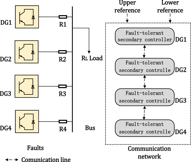
FIGURE 1. Simulation test system.
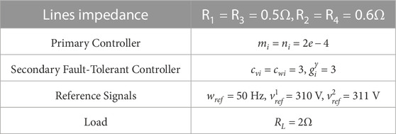
TABLE 1. The AC MG parameters and the fault-tolerant controller parameters.
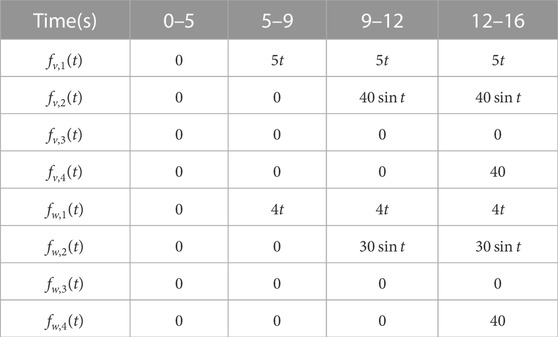
TABLE 2. The considered faults.
Case I. (Voltage and frequency regulation with distributed secondary controllers (Zhang et al., 2021) and (Anand et al., 2012)) In this case, the secondary controllers are added at t = 2 s. For the secondary controllers (Zhang et al., 2021) and (Anand et al., 2012), the trajectories of voltage and frequency under faults are shown in Figure 2. The simulation result can be summarized from the following stages.
1) Stage 1 (0–2 s): Only primary control is actuated. The frequency ωi is deviated from its reference value 50 Hz and the voltage Vi is also deviated from its reference range, i.e., [310,311].
2) Stage 2 (2–5 s): The secondary controllers (Zhang et al., 2021) and (Anand et al., 2012) are added at t = 2 s, which can restore the frequency ωi to its reference value and can also control the voltage Vi to [310,311].
3) Stage 3 (5–9 s): The trajectories of frequency ω1 deviate from its reference value and the trajectories of voltage V1 cannot stay within its scope under faults signal fv,1 and fw,1 as shown in Table 2.
4) Stage 4 (9–12 s): The trajectories of frequency ω1 and ω2 deviate from its reference value and the trajectories of voltages V1 and V2 cannot stay within its scope with the addition of fault signals fv,2 and fw,2.
5) Stage 5 (12- s): All trajectories of frequency ωi deviate from its reference value and the trajectories of voltage Vi cannot stay within its scope with the addition of fault signals fv,2 and fw,2.
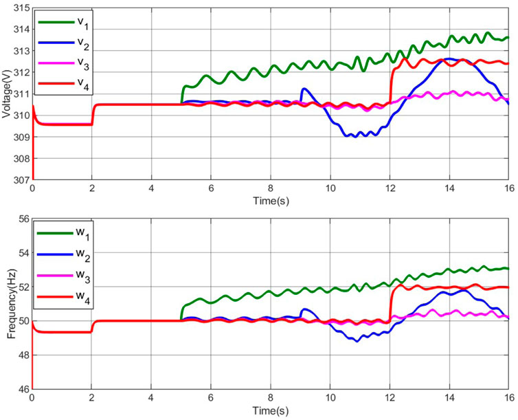
FIGURE 2. Trajectories of voltage and frequency with the distributed secondary controller (8)–(9) under faults.
In summary, under the distributed secondary controllers (Zhang et al., 2021) and (Anand et al., 2012)), the frequencies and voltages cannot be adjusted to the proper values under the influence of faults.
Case II. (Voltage and frequency regulation using distributed fault-tolerant controllers (31) and (38))
First, the parameters in the fault-tolerant controllers (31) and (38) are displayed in Table 3. Based on the distributed fault-tolerant controllers (31) and (38), the trajectories of voltage and frequency under the influence of faults are shown in Figure 3. Similar to case I, the following stages are shown.
1) Stage 1 (0–5 s): The conclusions are same to those in Stage 1 of Case I.
2) Stage 2 (5–16 s): The distributed fault-tolerant controllers (31) and (38) ensure that the frequency voltage are restored to their range.
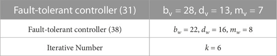
TABLE 3. Parameters of the designed fault-tolerant controller.
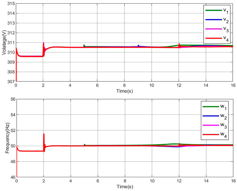
FIGURE 3. Trajectories of voltage and frequency with the secondary fault-tolerant controller (31) and (38) under faults.
Under the influence of the considered faults, the developed fault-tolerant control scheme can achieve the frequency recovery and voltage regulation effectively.
6 Conclusion
The distributed secondary fault-tolerant control problems of voltage and frequency regulation have been studied for smart grids under faults. A wavelet analysis and consensus algorithm-based fault-tolerant control method has been developed to solve the considered problems. In particular, the wavelet analysis technique is firstly introduced to detect the considered faults. Then, distributed secondary fault-tolerant controllers are designed to compensate for the influence of faults by using a newly introduced distributed fault estimate method. It is shown that the designed scheme ensures that both frequency regulation and voltage recovery objectives can be achieved. Finally, AC MGs with four distributed generations are used to validate the effectiveness of the developed fault-tolerant schemes.
Data availability statement
The original contributions presented in the study are included in the article/supplementary material, further inquiries can be directed to the corresponding author.
Author contributions
All the paper has been written by YH.
Funding
The work was supported by the basic scientific research project of Department of Education in 2022 of Liaoning Provincial of China under Grant LJKMZ20221993.
Conflict of interest
The authors declare that the research was conducted in the absence of any commercial or financial relationships that could be construed as a potential conflict of interest.
Publisher’s note
All claims expressed in this article are solely those of the authors and do not necessarily represent those of their affiliated organizations, or those of the publisher, the editors and the reviewers. Any product that may be evaluated in this article, or claim that may be made by its manufacturer, is not guaranteed or endorsed by the publisher.
Footnotes
1The details of (5) and (6) are given in the Appendix.
References
Anand, S., Fernandes, B., and Guerrero, J. (2012). Distributed control to ensure proportional load sharing and improve voltage regulation in low-voltage DC microgrids. IEEE Trans. Power Electron. 28 (4), 1900–1913. doi:10.1109/tpel.2012.2215055
Beg, O., Johnson, T., and Davoudi, A. (2017). Detection of false-data injection attacks in cyber-physical DC microgrids. IEEE Trans. Ind. Inf. 13 (5), 2693–2703. doi:10.1109/tii.2017.2656905
Bidram, A., and Davoudi, A. (2012). Hierarchical structure of microgrids control system. IEEE Trans. Smart Grid 3 (4), 1963–1976. doi:10.1109/tsg.2012.2197425
Chen, Y., Qi, D., Dong, H., Li, C., Li, Z., and Zhang, J. (2020). A FDI attack-resilient distributed secondary control strategy for islanded microgrids. IEEE Trans. Smart Grid 12 (3), 1929–1938. doi:10.1109/tsg.2020.3047949
Deng, C., WangWen, Y. C., Xu, Y., and Lin, P. (2020). Distributed resilient control for energy storage systems in cyber–physical microgrids. IEEE Trans. Ind. Inf. 17 (2), 1331–1341. doi:10.1109/tii.2020.2981549
Deng, C., Wen, C., Zou, Y., Wang, W., and Li, X. (2022). A hierarchical security control framework of nonlinear CPSs against DoS attacks with application to power sharing of AC microgrids. IEEE Trans. Cybern. 52 (6), 5255–5266. doi:10.1109/tcyb.2020.3029045
Ding, L., Han, Q., Ning, N., and Yue, D. (2019). Distributed resilient finite-time secondary control for heterogeneous battery energy storage systems under denial-of-service attacks. IEEE Trans. Ind. Inf. 16 (7), 4909–4919. doi:10.1109/tii.2019.2955739
Dou, C., Yue, D., and Guerrero, J. (2016). Multiagent system-based event-triggered hybrid controls for high-security hybrid energy generation systems. IEEE Trans. Ind. Inf. 13 (2), 584–594. doi:10.1109/tii.2016.2618754
Dragičević, T., Lu, X., Vasquez, J., and Guerrero, J. (2015). DC microgrids—Part I: A review of control strategies and stabilization techniques. IEEE Trans. Power Electron. 31 (7), 1–4891. doi:10.1109/tpel.2015.2478859
Fu, W., Ma, Q., Qin, J., and Kang, Y. (2021). Resilient consensus-based distributed optimization under deception attacks. Int. J. Robust Nonlinear Control 31 (6), 1803–1816. doi:10.1002/rnc.5026
Liu, Y., Ning, P., and Reiter, M. (2011). False data injection attacks against state estimation in electric power grids. ACM Trans. Inf. Syst. Sec. 14, 1–33. doi:10.1145/1952982.1952995
Lu, X., Guerrero, J., Sun, K., and Vasquez, J. (2013). An improved droop control method for DC microgrids based on low bandwidth communication with DC bus voltage restoration and enhanced current sharing accuracy. IEEE Trans. Power Electron. 29 (4), 1800–1812. doi:10.1109/tpel.2013.2266419
Mehrizi-Sani, A., and Iravani, R. (2012). Constrained potential function—based control of microgrids for improved dynamic performance. IEEE Trans. Smart Grid 3, 1885–1892. doi:10.1109/tsg.2012.2197424,
Modares, H., Kiumarsi, B., Lewis, F., Ferrese, F., and Davoudi, A. (2019). Resilient and robust synchronization of multiagent systems under attacks on sensors and actuators. IEEE Trans. Cybern. 50 (3), 1240–1250. doi:10.1109/tcyb.2019.2903411
Morstyn, T., Hredzak, B., and Agelidis, V. (2016). Control strategies for microgrids with distributed energy storage systems: An overview. IEEE Trans. Smart Grid 9 (4), 3652–3666. doi:10.1109/tsg.2016.2637958
Ge, P., Chen, B., and Teng, F., “ Event-triggered distributed model predictive control for resilient voltage control of an islanded microgrid,” Int. J. Robust Nonlinear Control, 31, 2001, 1979, 2000. doi:10.1002/rnc.5238
Sahoo, S., Mishra, S., Peng, J., and Dragičević, T. (2018). A stealth cyber-attack detection strategy for DC microgrids. IEEE Trans. Power Electron. 34 (8), 8162–8174. doi:10.1109/tpel.2018.2879886
Sánchez, H., Rotondo, D., Escobet, T., Puig, V., and Quevedo, J. (2019). Bibliographical review on cyber attacks from a control oriented perspective. Annu. Rev. Control 48, 103–128. doi:10.1016/j.arcontrol.2019.08.002
Savaghebi, M., Jalilian, A., Vasquez, J., and Guerrero, J. (2012). Secondary control scheme for voltage unbalance compensation in an islanded droop-controlled microgrid. IEEE Trans. Smart Grid 3 (2), 797–807. doi:10.1109/tsg.2011.2181432
Valenciaga, F., and Puleston, P. (2005). Supervisor control for a stand-alone hybrid generation system using wind and photovoltaic energy. IEEE Trans. Energy Convers. 20 (2), 398–405. doi:10.1109/tec.2005.845524
Wang, Z., and Passino, K. (2016). Stable reactive power balancing strategies of grid-connected photovoltaic inverter network. Int. J. Robust Nonlinear Control 26 (9), 2023–2046. doi:10.1002/rnc.3408
Zhang, H., Yue, D., Dou, C., Xie, X., Li, K., and Hancke, G. (2021). Resilient optimal defensive strategy of tSK fuzzy-model-based microgrids’ system via a novel reinforcement learning approach. IEEE Trans. Neural Netw. Learn. Syst. doi:10.1109/TNNLS.2021.3105668
Zhao, J., Mili, L., and Wang, M. (2018). A generalized false data injection attacks against power system nonlinear state estimator and countermeasures. IEEE Trans. Power Syst. 33 (5), 4868–4877. doi:10.1109/tpwrs.2018.2794468
Zhou, Q., Shahidehpour, M., Alabdulwahab, A., and Abusorrah, A. (2020). A cyber-attack resilient distributed control strategy in islanded microgrids. IEEE Trans. Smart Grid 11 (5), 3690–3701. doi:10.1109/tsg.2020.2979160
Keywords: secondary control, fault-tolerant control, voltage regulation, distributed control, AC micro grid
Citation: Han Y (2023) Wavelet analysis and consensus algorithm-based fault-tolerant control for smart grids. Front. Energy Res. 11:1160256. doi: 10.3389/fenrg.2023.1160256
Received: 07 February 2023; Accepted: 23 March 2023;
Published: 03 April 2023.
Edited by:
Xiao-Kang Liu, Huazhong University of Science and Technology, ChinaReviewed by:
Yao Weitao, Nanyang Technological University, SingaporeRui Wang, Northeastern University, China
Copyright © 2023 Han. This is an open-access article distributed under the terms of the Creative Commons Attribution License (CC BY). The use, distribution or reproduction in other forums is permitted, provided the original author(s) and the copyright owner(s) are credited and that the original publication in this journal is cited, in accordance with accepted academic practice. No use, distribution or reproduction is permitted which does not comply with these terms.
*Correspondence: Yunlong Han, eXVubG9uZ2hhbl9TSVNUQDEyNi5jb20=