 Xiyuan Ma1
 Peng Zhang
94% of researchers rate our articles as excellent or good
Learn more about the work of our research integrity team to safeguard the quality of each article we publish.
Find out more
ORIGINAL RESEARCH article
Front. Energy Res., 09 May 2023
Sec. Wind Energy
Volume 11 - 2023 | https://doi.org/10.3389/fenrg.2023.1159946
This article is part of the Research TopicOnline Monitoring of Wind Power Plants using Digital Twin ModelsView all 10 articles
As wind turbines are constantly replacing traditional units, it is becoming a consensus that wind turbines should participate in the grid support that was only responsible by traditional units in the past. In order to enhance the grid support capabilities (including active power support and reactive power support) of permanent magnet synchronous generator (PMSG) based wind turbines, this paper constructs an active and reactive power coordinated control strategy. Compared with the current active and reactive power coordinated control strategy of PMSG wind turbines, the method of the proposed one innovatively considers the climbing coordinated restriction between active and reactive power, flexible prioritization arrangement between active and reactive power, the accurate amplitude and climbing constraints of grid-side converters’ output voltage, and the model predictive control (MPC) technique. The simulation results verify that the proposed power control strategy can make PMSG wind turbines achieve excellent power output performance and thus better meet the requirements of power grid support.
Traditionally, the frequency and voltage of power systems are mainly controlled by thermal units and hydropower units. Wind and photovoltaic units account for a small generating capacity, and their power decouples with the grid frequency and voltage, standing at maximum power points and fixed power factors (Gaied et al., 2022; Zeng et al., 2022). However, with the implementation of the “double carbon” strategy in recent years, the installed capacity of wind and photovoltaic energy in China is increasing significantly, which reached approximate 706 GW by the end of September 2022 (National Energy Administration, 2023). The traditional units responsible for frequency and voltage control are gradually being replaced by the wind and photovoltaic units, which is gradually weakening the frequency and voltage control capability of power systems. Hence, it is a growing consensus that wind and photovoltaic units should provide frequency and voltage support services to power systems (i.e., grid support), so as to maintain the security operation of power systems (Hansen et al., 2006; Feltes et al., 2009).
Permanent magnet synchronous generator (PMSG) wind turbine, one of the mainstream wind turbines, is receiving more and more popularity nowadays (Guo et al., 2021). The strengths of a PMSG wind turbine include high energy efficiency and low maintenance costs (Li et al., 2012; Musarrat et al., 2019). In addition, a PMSG wind turbine contains a back-to-back full-scale converter for connecting to power systems so that power system faults and abnormal conditions will not directly affect the power output of the generator. This means that it holds inherent advantages in fault ride through and grid support (Tan et al., 2017; Sheng et al., 2021).
To provide grid support services, it is necessary for a PMSG wind turbine to adjust its active and reactive power to respond to the changes of grid frequency and voltage. Topics about power control strategies of a PMSG wind turbine/wind farm to provide grid support could be found in a great deal of literature (Wu et al., 2017; Peng et al., 2021; Zhong et al., 2021; Li et al., 2022; Okedu, 2022). For instance, a control strategy is proposed in literature (Wu et al., 2017) for a PMSG wind turbine coordinating with a battery system to provide frequency support, which is realized by instantly raising its active power to a predefined level once grid frequency disturbance occurs. In (Peng et al., 2021), the authors design a reactive voltage support method for a wind farm with static synchronous compensators considering remaining capacities and voltage unbalanced factors for different PMSG wind turbines. Yet, the power control strategies in literature (Wu et al., 2017; Peng et al., 2021; Zhong et al., 2021; Li et al., 2022; Okedu, 2022) do not fall under the category of coordinated control between active and reactive power.
Unlike loose regulatory codes for daily power generation, in the periods of providing grid support, the active and reactive power of a PMSG wind turbine is required to meet exact amplitude and response rate requirements, which are calculated based on the deviation or slope of frequency and voltage (Mohseni and Islam, 2012; Liu et al., 2015; You et al., 2015). In this context, active and reactive power coordinated control which involves active and reactive power coordinated restriction and priority decisions becomes an unavoidable and meaningful problem. On the one hand, active and reactive power coordinated restriction can improve the power control performance of a PMSG wind turbine in order to better provide grid support. On the other hand, when the apparent power of a PMSG wind turbine is greater than its rated apparent power, the priority of active and reactive power must be judged and then reduce the party with lower priority in order to ensure that the party with higher priority meets the power grid support requirements.
As shown in Figure 1, the shaded part represents the amplitude range of active and reactive power that PMSG wind turbines can output, which picture forms a semicircle or rectangle when active and reactive power is restricted coordinately or separately. To obey the given apparent power amplitude constraint, the semicircle’s radius is equal to maximum apparent power S, and the rectangle is contained in a semicircle with a radius of maximum apparent power S. Obviously, under the given apparent power amplitude constraint, active and reactive power amplitude coordinated restriction enables PMSG wind turbines to output a larger range of active and reactive power amplitude. By the same token, under the given apparent power climbing constraint, active and reactive power climbing coordinated restriction allows PMSG wind turbines to perform a larger range of active and reactive power climbing. Therefore, active and reactive power coordinated restriction is contributing to improving the PMSG wind turbines’ power control performance.
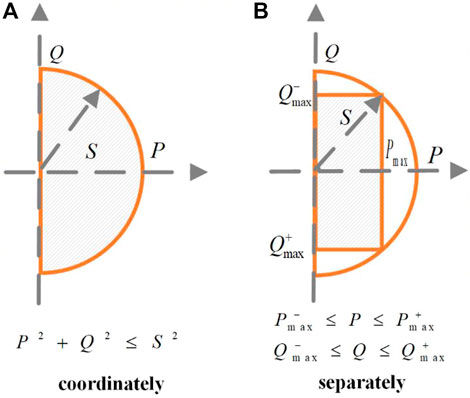
FIGURE 1. Amplitude range of active and reactive power that PMSG wind turbines can output. (A) coordinated restriction. (B) separated restriction.
For this reason, some literature pays attention to designing the coordinated control strategies of active and reactive power for PMSG wind turbines providing grid support (Nguyen et al., 2013; Moghadasi and Sarwat, 2015; Yan et al., 2016; Zhang et al., 2016; Tripathi et al., 2019). Ref (Dong et al., 2012). presents a coordinated control strategy to enhance the low voltage ride through and grid support capability of PMSG wind turbines. In (Khazaei et al., 2020), a consensus-based control strategy is proposed to regulate the output of PMSG wind turbines and distributed batteries in a wind farm to deliver active and reactive power to the load. These strategies only focus on amplitude coordinated restriction of active and reactive power, which will become more perfect if the climbing coordinated restriction of active and reactive power can be taken into account at the same time.
In summary, most previous power control strategies for PMSG wind turbines providing grid support either do not explore the coordinated control between active and reactive power, or only focus on amplitude coordinated restriction and ignore the climbing coordinated restriction between active and reactive power. In addition, the priority decisions of active and reactive power in previous power coordinated control strategies are not flexible enough to apply to multiple grid support scenarios. Model predictive control (MPC) (Rodriguez et al., 2009; Mayne, 2014), which can handle complex constraints and achieve multiple optimization objectives, is suitable to structure flexible power coordinated control strategies. MPC is numerous applicated in industrial process control (Qin and Badgwell, 2003; Venkat et al., 2008; Vazquez et al., 2014) and power control of PMSG wind turbines (Maaoui-Ben Hassine et al., 2016; Shehata, 2017; Mishra and Saha, 2020), while has not been found to be applicated in PMSG wind turbines’ active and reactive power coordinated control. Finally, the current MPC models on the PMSG wind turbines lack the accurate amplitude and climbing constraints of grid-side converters’ output voltage.
Based on the mentioned issues, this paper proposes an MPC based active and reactive power coordinated control strategy of PMSG wind turbines to enhance the grid support capability. The contributions of this article are as follows.
(1) Take the lead in adopting MPC to build an active and reactive power coordinated control strategy of PMSG wind turbines that can be flexibly applicated in different grid support scenarios due to the MPC can flexibly set the priority of active and reactive power.
(2) Not only the existing amplitude coordinated restriction between active and reactive power but also the innovative climbing coordinated restriction between active and reactive power is considered in the proposed control strategy, which enables PMSG wind turbines to perform a wider range of active and reactive power amplitude and climbing. So it enhances the power control performance and the grid support capability of PMSG wind turbines.
(3) The amplitude and climbing constraint model of grid-side converter voltage is structured in the proposed MPC based control strategy in order to protect the grid-side converters and dignify the output voltage waveform.
The rest of this paper is organized as follows. Section 2 describes the overview of PMSG wind turbines. Section 3 displays the mathematical model of PMSG wind turbines. The MPC based active and reactive power coordinated control strategy is introduced in Section 4 and simulated in Section 5. Finally, Section 6 summarizes this paper.
The composition of the PMSG wind turbine studied is shown in Figure 2, which mainly consists of a wind turbine, a PMSG, a back-to-back converter, and multiple controllers. In this paper, the generator-side converter is employed to maintain capacitor voltage and the grid-side converter controls active power to realize maximum power point tracking and provide grid frequency support. Meanwhile, the grid-side converter is also used to control the reactive power exchange to the power grid, so as to provide grid voltage support. Therefore, the key to providing frequency and voltage support for the power grid is to control the active and reactive power of the grid-side converter.
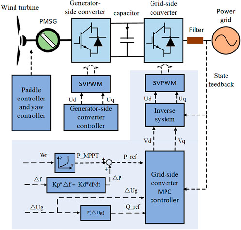
FIGURE 2. The composition of the PMSG wind turbine studied.
In order to obtain the wider range of active and reactive power amplitude and climbing under the given apparent power amplitude and climbing constraints, in this paper, both the amplitude coordinated restriction and climbing coordinated restriction of the grid-side converter’s active and reactive power are considered. In view of the obvious advantages of MPC in dealing with multi-input and multi-output control problems with complex constraints and specific objectives, this paper applies MPC to struct the active and reactive power coordinated control strategy of the grid-side converter.
The MPC based active and reactive power coordinated control system of the grid-side converter is presented in Figure 2. The MPC controller uses the predictive model of the controlled system to predict the behavior of the controlled system under different control actions and selects the optimal control action which minimizes the objective function. According to the situations of the power grid and the PMSG wind turbine, the objective function is automatically adjusted so that the proposed control strategy can adapt to different grid support scenarios.
Firstly, the mathematical model of the grid-side converter is established. Secondly, an inverse system is designed in order to change the grid-side converter into a pseudolinear composite system. Thirdly, the prediction model and constraint conditions of the MPC controller are built according to the state space equation and operation boundary of the pseudolinear composite system, and the objective function of the MPC controller is built according to the reference value and priority of active and reactive power. Finally, the optimal control action is obtained by solving the optimization problem.
By analyzing the three-phase circuit between the grid-side converter and the power system as shown in Figure 2, the three-phase mathematical model of the grid-side converter system can be written as follows:
where
The three-phase mathematical model (1) of the grid-side converter can be transformed to a mathematical model in dq synchronously rotating reference frame, which can be expressed as follows.
where
It can be seen that the nonlinearities exist in the grid-side converter’s mathematical model (2) since it contains the nonlinear terms
It is worth mentioning that, due to the need to solve the optimization model, the sampling interval of an MPC controller cannot be set as a small value, while the sampling interval of an inverse system can be set to very small, so the inverse system can sample the state variables (id and iq), amplitude
As shown in Figure 2,
Therefore, a grid-side converter composite system is structed which inputs are
The state variables and output variables of the composite system are the same as those of the grid-side converter system. Therefore, to control the composite system is essential to control the converter system grid-side converter system.
The state representation Eq. 2 of the grid-side converter system contains the nonlinear terms
The grid-side converter composite system model (6)–(7) can be written as a normal linear state space model.
If the amplitude of the grid voltage is stable, the system model can accurately describe the output characteristic of the system. So that the MPC controller can accurately predict and control the outputs of the system. The system outputs will gradually reach the reference values under the control of the MPC controller.
In contrast, if the amplitude of the grid voltage changes after being measured, this means that the output characteristic of the system has changed and does not match the currently established system model during this sampling interval. The MPC controller may not achieve the expected effect of predicting and controlling the system outputs during this sampling interval. However, the system model will be corrected because the MPC controller will re-measure the grid voltage amplitude at the beginning of the next sampling interval. Based on the correct system model, the system outputs will gradually reach the reference values under the control of the MPC controller. Therefore, the change of the grid voltage amplitude will not cause the system to lose stability, but make the outputs of the system fail to reach the expected value within the current sampling interval.
The MPC algorithm is not executed continuously in the controller, but at regular interval, which is called sampling interval or control period and is denoted by T. Discretization (8) can result in
where
The prediction horizon refers to the time range from the current time point to a certain time point in the future. The MPC algorithm needs to predict the state variables of the composite system in this time range. The time length of the prediction horizon is an integral multiple of the MPC sampling interval/control interval, so it can be expressed as NP*T. Similarly, The control horizon refers to the time range from the current time point to a certain time point in the future. The MPC algorithm needs to compute the optimal control variables of the composite system in this time range. The time length of the control horizon is an integral multiple of the MPC sampling interval/control interval, so it can be expressed as NC*T.
In this paper, NP = 3 and NC = 2 when we introduce the formulas of the optimization problem. This means that the MPC algorithm needs to predict the state variables of the system from the time t = (k+1)*T to the time t = (k+ 3)*T, meanwhile, the MPC algorithm needs to compute the optimal control variables of the system in the period from the time t = kT to the future time t = (k+2)*T. In fact, they can take other values. With the increase in the NP and NC, the computing time and controller performance of the MPC algorithm will increase. When setting the values of NP and NC, it is necessary to ensure that the computing time of the MPC algorithm cannot exceed the MPC sampling interval.
In each sampling interval, the MPC controller solves the optimization problem (8–23) and obtains the optimal control variables
Generalized power amplitude constraint conditions include the power amplitude constraints and current amplitude constraints. Based on the discrete state-space model (9), the grid current amplitudes in the future triple control periods can be predicted as follows.
The prediction model (10) of grid current amplitudes can be rewritten in matrix form.
The future grid current amplitudes should not be greater than of the rated current amplitude of the grid-side converter. Then, we have.
Compared to separately restricting each active current
Similarly, based on discrete state-space model (9), the power amplitudes in the future triple control periods can be predicted.
The prediction model (12) of the power amplitudes can be rewritten in matrix form.
The future apparent power amplitudes of the grid-side converter should not be greater than its rated apparent power amplitude. Then, we have.
Compared to separately restricting each active power
Based on the state space model (6)–(9), we can see that the climbing of active power and reactive power depends on the control variables
Compared to separately restricting each control input such as
In order to protect the grid-side converter and dignify the output voltage waveform, the amplitude coordinated restriction and climbing coordinated restriction between grid-side converter voltages
(1) The variation characteristic of the control variables
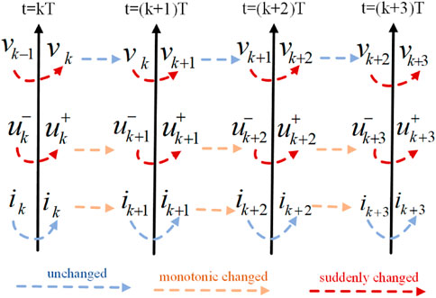
FIGURE 3. The variation characteristic of the control variables, current and converter voltage.
As mentioned above, The MPC algorithm is not executed continuously, but at regular control period T. At the starting point of each control period T, the MPC controller solves the MPC algorithm and outputs a new round of control variables
Therefore, during a control period T, the control variables
(2) The variation characteristic of the current
According to mathematical model (6), it can be seen that the change rates of the current
(3) The variation characteristic of the converter voltage
Based on inverse system model (5), the derivative of the converter voltage
At the moments of two control period junctures (such as t = kT…t=(k+3)T), the MPC controller will give a new round of control variables
Based on the inverse system model (5), the future converter voltage
The prediction model (17) of converter voltage can be rewritten in matrix form.
Based on the inverse system model (5), the future converter voltage
The prediction model (19) of converter voltage can be rewritten in matrix form.
The future voltage amplitudes of the grid-side converter should not be greater than its rated voltage amplitude. Then, we have.
As shown in Figure 3, at the moments of two control period T junctures (such as t = kT…t=(k+3)T), the output converter voltage
The square of the current amplitude is
It can be seen that the second derivatives of both
The optimization objective is to minimize the deviations between the output values and reference values of the grid-side converter composite system’s active and reactive power.
When the apparent power reference of the grid-side converter composite system lesser than its rated apparent power, the output values of active and reactive power can reach their reference values. If the apparent power reference is greater than rated apparent power, the priority of active and reactive power must be set and the party with lower priority cannot reach its reference.
This paper sets the priority of active and reactive power by setting the deviation coefficients
According to the National standard of China “Technical Regulations for Wind Farm Access to Electric Power System, GB/T 19963.1-2021”, when the grid voltage change is in the domain of
Therefore, in the proposed control strategy, according to the situation of the power grid and the PMSG wind turbine, the deviation coefficients
The optimization problem of the MPC controller can be sort out as follows
where
To avoid the feasible set determined by the constraints becoming empty, the optimization problem (24) can be modified as follows.
The optimization variables
The slack optimization variables
The control system including the MPC controller and the grid-side converter composite system. Stability analysis is to construct an energy function for the control system and determine whether the energy function meets the stability conditions. The energy function chosen here is
1)
If
If
Therefore,
2) when
Firstly,
If
3) If
When judging the change trend of the energy function
When initial state variables are
If the value taking of the original optimization variables
On the contrary, if the value taking of the original optimization variables
Given that the optimal variables obtained
Under the control of the MPC controller, in the next sampling interval, the system state variables changes to
If
By analogy, if the state vector is not 0 vector, the energy function
The optimization problem (25) is a convex optimization problem with a convex quadratic objective function and multiple convex quadratic constraints which can be solved in many ways. Specifically, a convex optimization problem can be sort out as the following general form.
where
where
In (29), equality constraints are used to solve the optimal solution, and inequality constraints are used to verify the optimal solution. It is worth mentioning that in addition to the above method, there are many solving methods (An, 2000) and mature commercial solvers for convex optimization problems. The commercial solvers (Gurobi optimization, 2023; IBM CPLEX Optimizer, 2023) can be used to solve convex optimization problems conveniently and quickly, without the need for users to write optimization programs.
In each sampling interval T, the actions of the MPC controller include measuring the system states, constructing and solving the optimization problem (8–23), and providing the optimal control variables (Vd and Vq) to the system. The flow of the MPC algorithm is shown in Figure 4.
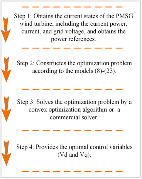
FIGURE 4. The flow of the MPC algorithm.
The performance of the proposed active and reactive power coordinated control strategy is evaluated in this section by testing the tracking performance of the PMSG wind turbine to the active and reactive power step references. The references of active and reactive power are shown in Figure 5. In order to capture maximum wind energy, the active power reference remains at 2.5 MW unchanged. The grid voltage stays in the rated value at 0–0.2s and the reactive power reference is set as 0.1 MW at 0–0.2 s. While the grid voltage drops down to 50% of the rated value at 0.2 s and the duration is 0.6 s. According to the reactive current support requirements in grid codes [21], the reactive power reference is stepped from 0.1 MW to 1.35 MW at 0.2 s.
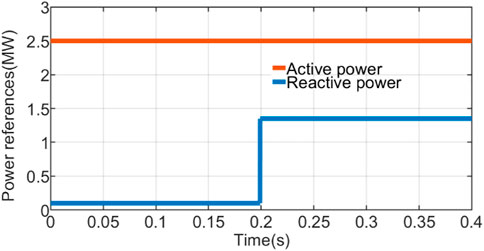
FIGURE 5. The active and reactive power step references of the PMSG wind turbine.
Three different scenarios are simulated in this section using MATLAB/Simulink.
S1: Active and reactive power are controlled using the MPC controller without coordinated restrictions and priority arrangement
S2: Active and reactive power are coordinately controlled using the MPC controller, which considers amplitude coordinated restrictions and priority arrangement of active and reactive power.
S3: Active and reactive power are coordinately controlled using the MPC controller, which considers amplitude coordinated restrictions and priority arrangement of active and reactive power. Meanwhile, the climbing coordinated restrictions of active and reactive power is considered.
S4: Active and reactive power are coordinately controlled using the PI controller, which considers amplitude coordinated restrictions and priority arrangement of active and reactive power.
The other conditions and parameters in the three simulated scenarios are the same. The parameters of the grid-side converter system are indicated in Table 1 (Yaramasu and Wu, 2014). The prediction horizon is set as five times control period T and the control horizon is set as four times control period T when simulating.
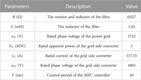
TABLE 1. Parameters of the grid-side converter system.
Figures 6–8 depict the power reference tracking results of the PMSG wind turbine in the three different scenarios. Due to the grid voltage droping down to 50% of the rated value at 0.2 s, the maximum apparent power of the PMSG wind turbine change from 3MW to 1.5 MW at 0.2 s. In Scenario S1, the active and reactive power coordinated restrictions and priority decisions are not considered. Regardless of the power grid status, the amplitude range and climbing range of active and reactive power are fixed and do not interfere with each other. Therefore, the PMSG wind turbine cannot guarantee reactive power output by reducing the active power output. Therefore, when the grid voltage drop, the reactive power of the PMSG wind turbine cannot meet the 1.35 MW reference which is the reactive power support requirement.
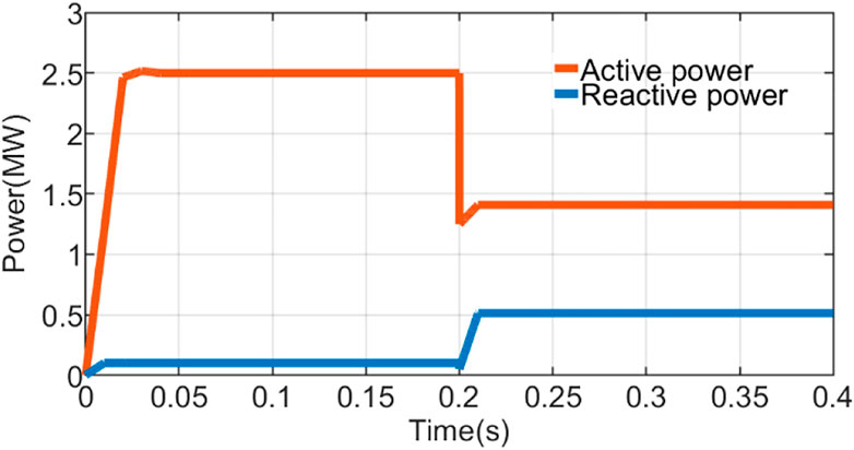
FIGURE 6. The power references tracking results of the PMSG wind turbine in the S1 scenario.
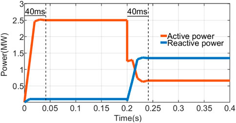
FIGURE 7. The power references tracking results of the PMSG wind turbine in the S2 scenario.
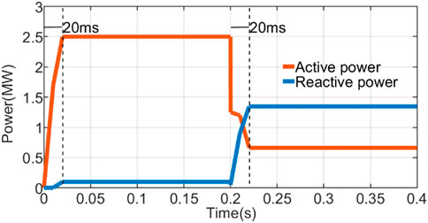
FIGURE 8. The power references tracking results of the PMSG wind turbine in the S3 scenario.
Amplitude coordinated restrictions and priority decisions of active and reactive power are considered in Scenario S2. When the grid voltage drops down to 50% of the rated value at 0.2s, the priority task of the PMSG wind turbine is to provide reactive power support for the grid voltage recovery, and of cause the reactive power priority is set higher. As shown in Figure 6, by reducing the amplitude of active power, the PMSG wind turbine can output 1.35 MW reactive power to meet the reactive power support requirements of the grid. That is why we say it is very necessary and meaningful to coordinately control the active and reactive power amplitude of the wind turbine under the background of grid support.
The proposed control strategy in this paper is simulated in Scenario 3 which considers amplitude and climbing coordinated restrictions and priority decisions between active and reactive power. Similarly to Scenario 2, the PMSG wind turbine can meet the reactive power support requirements of the grid when the grid voltage drops. The difference between Scenario 2 and Scenario 3 is that, the PMSG wind turbine shows a faster response speed in Scenario 3, which the dynamic time in Scenario 3 is 20 ms and it is 40 ms in Scenario 2. This demonstrates the superiority of the control strategy proposed in this paper.
Figures 9, 10 show the current climbing of the PMSG wind turbine in Scenario 2 and Scenario 3. It can be found that the active and reactive current climbing limit value of the PMSG wind turbine in Scenario 3 is larger than that in Scenario 2. The greater ability to climb allows the PMSG wind turbine to show faster response speed in response to a step change in the power reference value. The results explain why the PMSG wind turbine shows a faster response speed in Scenario 3. The simulation results verify that under the given apparent power/current climbing constraint, active and reactive power/current climbing coordinated restrictions allow PMSG wind turbines to perform a larger range of active and reactive power/current climbing.

FIGURE 9. The power climbing of the PMSG wind turbine in Scenario 2.
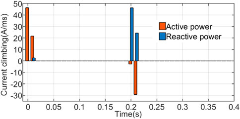
FIGURE 10. The power climbing of the PMSG wind turbine in Scenario 3.
The voltage of the grid-side converter is shown in Figure 11 when the PMSG wind turbine executes the proposed control strategy in Scenario 3. It is easy to see that the voltage amplitude does not exceed its maximum allowed value in the whole process. In addition, there are no sharp climb and spike in the voltage waveform, which can protect the grid-side converters and improve the electricity quality of the PMSG wind turbine. Hence, The voltage amplitude and climbing constraint model proposed in this paper is effective.
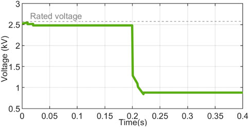
FIGURE 11. The voltage of the grid-side converter in Scenario 3.
The three-phase current of the grid-side converter is shown in Figure 12 when the PMSG wind turbine executes the proposed control strategy in Scenario 3. The rated peak value of single-phase current is 0.816 kA. It is easy to see that the amplitudes of the three-phase current do not exceed the rated peak value 0.816 kA in the whole process. In addition, there are no sharp climb and spike in the three-phase current waveforms, which can protect the grid-side converters and improve the electricity quality of the PMSG wind turbine. Hence, The current amplitude and climbing constraint model proposed in this paper is effective.
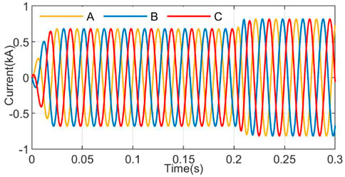
FIGURE 12. The three-phase current of the grid-side converter in Scenario 3.
Figure 13 shows the result of the PMSG wind turbine tracking a 3 MW step active power reference, which is simulated with different prediction horizons. As can be seen from Figure 13, when the prediction horizon is short (Np = 1), the output of the PMSG wind turbine exists the overshoot. This is because the MPC model in this paper contains constraints on the power climbing change. The active power output of the PMSG wind turbine has a large climbing in the early stage, and the climbing cannot be changed quickly after approaching the active power reference value, so overdrive occurs. When the prediction horizon is long, the MPC controller can predict the corresponding future multi-step power output under different control variables, and select the optimal control variable to avoid overshoot. It is worth mentioning that the longer the prediction horizon, the better the control effect. In the scenario, the control effect is exactly the same when Np = 5 as when Np = 9. It is worth mentioning that as the prediction horizon increases, the control effect will not get better. In the current scenario, the control effect is exactly the same when Np = 5 and Np = 9.
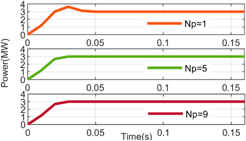
FIGURE 13. The active power references tracking results of the PMSG wind turbine under different prediction horizon.
In the proposed MPC based control strategy, the priority of active and reactive power can be flexibly arranged by setting the deviation coefficients
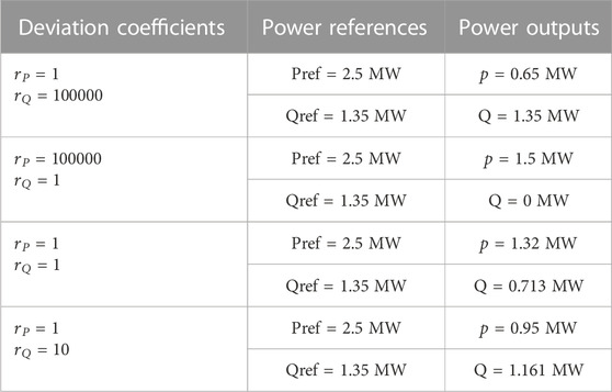
TABLE 2. The steady-state amplitude of active and reactive power with different deviation coefficients.
Figures 14, 15 depict the power reference tracking results and the grid-side converter voltage of the PMSG wind turbine when the PMSG wind turbine is controlled by a PI controller in Scenario 4. It can be seen in Figure 14 that there are overshoots and steady-state errors existing when the PMSG wind turbine tracks the active power references. It is worth mentioning that increasing the integral parameter in the PI controller can eliminate steady-state errors, but can lead to larger overshoots. As can be seen in Figure 15, the grid-side converter voltage may exceed its rated value during the dynamic process, which may cause damage to the grid-side converter and degrade the power quality. In addition, the amplitudes of output power and the grid-side converter voltage continue to fluctuate during the steady state period. This means that the power quality of the PMSG wind turbine output is lower.

FIGURE 14. The power references tracking results of the PMSG wind turbine in the S4 scenario.
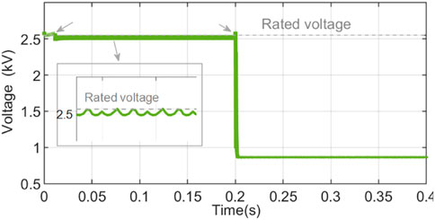
FIGURE 15. The voltage of the grid-side converter in Scenario 4.
As shown in Figures 8–13, the MPC based active and reactive power coordinated control strategy proposed in this paper can enable one of active power and reactive power (the one with higher priority) to track its references perfectly with zero steady-state error, zero overshoot and transient dynamic process. The steady-state power curve and the steady-state voltage curve are smooth straight lines. The power amplitude constraint, power climbing constraint, power priority arrangement, voltage amplitude constraint and voltage ramp constraint set in the proposed control strategy have achieved the expected results. That is because the MPC controller is good at dealing with multi-input and multi-output control problems with complex constraints and specific objectives. The above complex constraints and specific objectives are difficult to implement by PI controllers.
In this paper, an MPC based active and reactive power coordinated control strategy is proposed to enhance the power control performance and grid support capability of PMSG wind turbines. Firstly, the constraint conditions in the MPC controller are constructed which include amplitude and climbing coordinated restrictions between active and reactive power, voltage amplitude and climbing constraints of grid-side converters. These constraint conditions enable PMSG wind turbines to perform a wider range of active and reactive power amplitude and climbing, and a smoother output voltage waveform. Then, an objective function is constructed to minimize the deviation of active and reactive power from their reference values. By setting the deviation coefficients in the objective function, the priority of active power output and reactive power output can be flexibly arranged. So that PMSG wind turbines can meet the power output requirements in different grid support scenarios. In the end, the simulation results show that the proposed control strategy can make PMSG wind turbines achieve excellent power control performance and thus better meet the requirements of power grid support. In the future, the influences of sampling delay and MPC calculation delay on the proposed control strategy will be analyzed and the proposed control strategy will be improved by using delay compensation technology.
The original contributions presented in the study are included in the article/Supplementary Material, further inquiries can be directed to the corresponding author.
XM proposed the idea and carried out the model establishment, simulation experiment, result analysis, meanwhile he wrote the first draft. JY assisted in establishment of model and improvement of the idea. PY was in charge of knowledge coaching and error correction. PW is responsible for data collection, analysis, and processing and assisted in result analysis. PZ helped the revision of the manuscript and typeset the manuscript.
This work was supported by Key-Area Research and Development Program of Guangdong Province (2021B0101230003), and The Research Project of Digital Grid Research Institute, China Southern Power Grid (670000KK52220011).
The authors declare that the research was conducted in the absence of any commercial or financial relationships that could be construed as a potential conflict of interest.
All claims expressed in this article are solely those of the authors and do not necessarily represent those of their affiliated organizations, or those of the publisher, the editors and the reviewers. Any product that may be evaluated in this article, or claim that may be made by its manufacturer, is not guaranteed or endorsed by the publisher.
An, L. T. H. (2000). An efficient algorithm for globally minimizing a quadratic function under convex quadratic constraints. Math. Program. Ser. B 87, 401–426. doi:10.1007/s101070050003
Dong, S., Wang, Y., and Li, H. (2012). Coordinated control for active and reactive power of PMSG-based wind turbine to enhance the LVRT capability. 2012 15th int. Conf. Electr. Mach. Syst., (ICEMS), 33–36.
Feltes, C., Engelhardt, S., Kretschmann, J., Fortmann, J., Koch, F., and Erlich, I. (2009). Comparison of the grid support capability of DFIG-based wind farms and conventional power plants with synchronous generators. 2009 IEEE power energy soc. Gen. Meet., 1–7. doi:10.1109/PES.2009.5275441
Gaied, H., Naoui, M., Kraiem, H., Goud, B. S., Flah, A., Alghaythi, M. L., et al. (2022). Comparative analysis of MPPT techniques for enhancing a wind energy conversion system. Front. Energy Res. 10, 1–15. doi:10.3389/fenrg.2022.975134
Guo, L., Ren, Y., Wang, Z., Zhu, X., Wang, X., Li, X., et al. (2021). Double-layer feedback control method for synchronized frequency regulation of PMSG-based wind farm. IEEE Trans. Sustain. Energy 12, 2423–2435. doi:10.1109/TSTE.2021.3096724
Gurobi optimization (2023). Gurobi. Available at: http://www.gurobi.com (Accessed Feb, 2023).
Hansen, A. D., Sørensen, P., Iov, F., and Blaabjerg, F. (2006). Grid support of a wind farm with active stall wind turbines and AC grid connection. Wind Energy 9, 341–359. doi:10.1002/we.176
IBM CPLEX Optimizer (2023). High-performance mathematical programming solver for linear programming, mixed integer programming, and quadratic programming. Available at: https://www.ibm.com/cn-zh/analytics/cplex-optimizer (Accessed Feb, 2023).
Khazaei, J., Nguyen, D. H., and Asrari, A. (2020). Consensus-based demand response of PMSG wind turbines with distributed energy storage considering capability curves. IEEE Trans. Sustain. Energy 11, 2315–2325. doi:10.1109/TSTE.2019.2954796
Li, Q., Ren, B., Li, Q., Wang, D., Tang, W., Meng, J., et al. (2022). Virtual inertial control strategy based on fuzzy logic algorithm for PMSG wind turbines to enhance frequency stability. Front. energy Res. 10, 1–9. doi:10.3389/fenrg.2022.907770
Li, S., Haskew, T. A., Swatloski, R. P., and Gathings, W. (2012). Optimal and direct-current vector control of direct-driven PMSG wind turbines. IEEE Trans. Power Electron. 27, 2325–2337. doi:10.1109/TPEL.2011.2174254
Liu, Y., Gracia, J. R., King, T. J., and Liu, Y. (2015). Frequency regulation and oscillation damping contributions of variable-speed wind generators in the U.S. Eastern interconnection (EI). IEEE Trans. Sustain. Energy 6, 951–958. doi:10.1109/TSTE.2014.2318591
Maaoui-Ben Hassine, I., Naouar, M. W., and Mrabet-Bellaaj, N. (2016). Predictive control strategies for wind turbine system based on permanent magnet synchronous generator. ISA Trans. 62, 73–80. doi:10.1016/j.isatra.2015.12.002
Mayne, D. Q. (2014). Model predictive control: Recent developments and future promise. Automatica 50, 2967–2986. doi:10.1016/j.automatica.2014.10.128
Mishra, R., and Saha, T. K. (2020). Performance analysis of model predictive technique based combined control for PMSG-Based distributed generation unit. IEEE Trans. Ind. Electron. 67, 8991–9000. doi:10.1109/TIE.2020.2992970
Moghadasi, A., and Sarwat, A. I. (2015). Optimal analysis of resistive superconducting fault current limiters applied to a variable speed wind turbine system. Conf. Proc. - IEEE S., 1–7. doi:10.1109/SECON.2015.7132944
Mohseni, M., and Islam, S. M. (2012). Review of international grid codes for wind power integration: Diversity, technology and a case for global standard. Renew. Sustain. Energy Rev. 16, 3876–3890. doi:10.1016/j.rser.2012.03.039
Musarrat, N., Islam, R., Member, S., Muttaqi, K. M., and Member, S. (2019). Enhanced frequency support from a PMSG-based wind energy conversion system integrated with a high temperature SMES in standalone power supply systems. IEEE Trans. Appl. Supercond. 29, 1–6. doi:10.1109/tasc.2018.2882429
National Energy Administration (2023). Transcript of the online press conference of the National Energy Administration in the fourth quarter of 2022. Available at: http://www.nea.gov.cn/2022-11/14/c_1310676392.htm (Accessed Feb, 2023).
Nguyen, T. H., Lee, D. C., Van, T. L., and Kang, J. H. (2013). Coordinated control of reactive power between STATCOMs and wind farms for PCC voltage regulation. J. Power Electron. 13, 909–918. doi:10.6113/JPE.2013.13.5.909
Okedu, K. E. (2022). Improving the performance of PMSG wind turbines during grid fault considering different strategies of fault current limiters. Front. Energy Res. 10, 1–12. doi:10.3389/fenrg.2022.909044
Peng, Y., Li, Y., Lee, K. Y., Tan, Y., Cao, Y., Wen, M., et al. (2021). Coordinated control strategy of pmsg and cascaded H-bridge STATCOM in dispersed wind farm for suppressing unbalanced grid voltage. IEEE Trans. Sustain. Energy 12, 349–359. doi:10.1109/TSTE.2020.2995457
Qin, S. J., and Badgwell, T. A. (2003). A survey of industrial model predictive control technology. Control Eng. Pract. 11, 733–764. doi:10.1016/S0967-0661(02)00186-7
Rodriguez, J., Cortes, P., Kennel, R., and Kazmierkowski, M. P. (2009). Model predictive control - a simple and powerful method to control power converters. IEEE Trans. Ind. Electron. 56, 41–49. doi:10.1109/IPEMC.2009.5289335
Shehata, E. G. (2017). A comparative study of current control schemes for a direct-driven PMSG wind energy generation system. Electr. Power Syst. Res. 143, 197–205. doi:10.1016/j.epsr.2016.10.039
Sheng, Y., Li, C., Jia, H., Liu, B., Li, B., and Coombs, T. A. (2021). Investigation on FRT capability of PMSG-based offshore wind farm using the SFCL. IEEE Trans. Appl. Supercond. 31, 2021–2024. doi:10.1109/TASC.2021.3091054
Tan, Y., Member, S., Muttaqi, K. M., Member, S., Ciufo, P., Member, S., et al. (2017). Enhanced frequency response strategy for a PMSG-based wind energy conversion system using ultracapacitor in remote area power supply systems. IEEE Trans. Ind. Appl. 53, 549–558. doi:10.1109/tia.2016.2613074
Tripathi, S. M., Tiwari, A. N., and Singh, D. (2019). Low-voltage ride-through enhancement with the ω and T controls of PMSG in a grid-integrated wind generation system. IET Gener. Transm. Distrib. 13, 1979–1988. doi:10.1049/iet-gtd.2018.6275
Vazquez, S., Leon, J., Franquelo, L., Rodriguez, J., Young, H., Marquez, A., et al. (2014). Model predictive control. IEEE Ind. Electron. Mag. 8, 91–94. doi:10.1007/978-3-319-91707-8_12
Venkat, A. N., Hiskens, I. A., Rawlings, J. B., and Wright, S. J. (2008). Distributed MPC strategies with application to power system automatic generation control. IEEE Trans. Control Syst. Technol. 16, 1192–1206. doi:10.1109/TCST.2008.919414
Wu, Z., Gao, D. W., Member, S., Zhang, H., Yan, S., and Wang, X. (2017). Coordinated control strategy of battery energy storage system and PMSG-WTG to enhance system frequency regulation capability. IEEE Trans. Sustain. Energy 8, 1330–1343. doi:10.1109/tste.2017.2679716
Xu, Y., Wang, W., and Gao, Z. (2001). The algorithm of sequential KKT equations by nonmonotone search for arbitrary initial point. Comput. Optim. Appl. 18, 221–232. doi:10.1023/A:1011281102385
Yan, Z., Chen, M., Zhen, X., Li, X., and Wubin, W. (2016). An experimental system for LVRT of direct-drive PMSG wind generation system. 2016 IEEE 8th int. Power electron. Motion control conf. Hefei: IPEMC-ECCE Asia 2016, 1452–1456. doi:10.1109/IPEMC.2016.7512505
Yaramasu, V., and Wu, B. (2014). Predictive control of a three-level boost converter and an NPC inverter for high-power PMSG-based medium voltage wind energy conversion systems. IEEE Trans. Power Electron. 29, 5308–5322. doi:10.1109/TPEL.2013.2292068
You, R., Barahona, B., Chai, J., and Cutululis, N. A. (2015). Frequency support capability of variable speed wind turbine based on electromagnetic coupler. Renew. Energy 74, 681–688. doi:10.1016/j.renene.2014.08.072
Zeng, C., Yang, B., Cao, P., Li, Q., Deng, J., and Tian, S. (2022). Current status, challenges, and trends of maximum power point tracking for PV systems. Front. Energy Res. 10, 1–5. doi:10.3389/fenrg.2022.901035
Zhang, B., Hu, W., Hou, P., Soltani, M., and Chen, Z. (2016). “Coordinated power dispatch of a PMSG based wind farm for output power maximizing considering the wake effect and losses,” in 2016 IEEE power energy soc. Gen. Meet. (PESGM), 1–5. doi:10.1109/PESGM.2016.7741738
Keywords: grid support, permanent magnet synchronous generator (PMSG) wind turbine, active and reactive power coordinated control strategy, model predictive control (MPC), amplitude and climbing
Citation: Ma X, Yu J, Yang P, Wang P and Zhang P (2023) An MPC based active and reactive power coordinated control strategy of PMSG wind turbines to enhance the support capability. Front. Energy Res. 11:1159946. doi: 10.3389/fenrg.2023.1159946
Received: 06 February 2023; Accepted: 17 April 2023;
Published: 09 May 2023.
Edited by:
Taeseong Kim, Technical University of Denmark, DenmarkReviewed by:
Alan Wai Hou Lio, Technical University of Denmark, DenmarkCopyright © 2023 Ma, Yu, Yang, Wang and Zhang. This is an open-access article distributed under the terms of the Creative Commons Attribution License (CC BY). The use, distribution or reproduction in other forums is permitted, provided the original author(s) and the copyright owner(s) are credited and that the original publication in this journal is cited, in accordance with accepted academic practice. No use, distribution or reproduction is permitted which does not comply with these terms.
*Correspondence: Ping Yang, ZXBweWFuZ0BzY3V0LmVkdS5jbg==
Disclaimer: All claims expressed in this article are solely those of the authors and do not necessarily represent those of their affiliated organizations, or those of the publisher, the editors and the reviewers. Any product that may be evaluated in this article or claim that may be made by its manufacturer is not guaranteed or endorsed by the publisher.
Research integrity at Frontiers
Learn more about the work of our research integrity team to safeguard the quality of each article we publish.