 Livio Santos
 Arash Dahi Taleghani
- Earth and Mineral Sciences Energy Institute, Pennsylvania State University, University Park, PA, United States
To ensure feasible power generation from closed-loop geothermal wells, deeper wells are required to reach higher temperature zones. However, weak bonding between cement and casing or cement and formation may allow formation of a small gap (known as microannulus), which could have a negative effect on the heat extraction rate and consequently compromises the entire investment. Previous projects have reported that the output temperatures were significantly lower than the expected values, and the cause is believed to be cement debonding. This study aims to develop a reliable simulation model to demonstrate the impact of microannulus in closed-loop geothermal systems. Multi-physics finite element analysis is used to construct models with and without microannulus. The microannulus is modeled based on real cement evaluation logs, with gaps varying between a few micrometers to few millimeters. In extreme cases, the presence of microannulus is found to decrease the geothermal power by more than 35%. Furthermore, the possibility of heat loss containment is investigated by a sensitivity study of wellbore parameters. These sensitivity analyses demonstrate that cement and geothermal fluids with higher thermal conductivity can improve but cannot compensate the presence of microannuli. The results also highlight the importance of proper cementing design to ensure wellbore integrity and avoid geothermal power loss.
1 Introduction
In a geothermal closed-loop system, a working fluid is circulated through a single well in a closed-circuit through a U-tube or coaxial pipes called borehole heat exchangers (BHE) or down-hole heat exchangers (DHX). In the U-Tube, a working fluid flows from the surface down one leg of the pipe to the target geothermal resource and then flows back to the surface through another leg carrying the accumulated heat. Whereas the BHE consists of insulated tubing inserted into the well with an open end at the lowest point, allowing production (Figure 1). Shallow BHEs are widely used as a reliable source for heat pumps, and in Switzerland alone, more than 20,000 plants are in operation, with borehole depths between 50 and 350 m (Rybach et al., 2000). Deep borehole heat exchangers are not currently used for economic reasons as such installations are unprofitable at current heat prices. However, technological advances in the drilling industry, as well as improvements in insulation materials, have led to a significant decrease in installation costs for geothermal wells in recent years. Furthermore, there is growing interest in repurposing abandoned oil and gas wells for geothermal energy production, with a particular focus on the implementation of closed-loop systems (Santos et al., 2022). This presents an exciting opportunity for the widespread adoption of geothermal energy, given the millions of drilled oil wells worldwide that could potentially be utilized in this way. As a forward-looking source of heat, geothermal energy holds significant promise for meeting our energy needs in a sustainable and environmentally responsible manner.
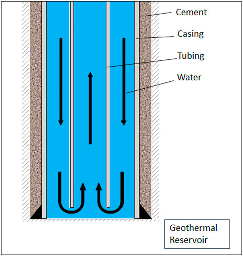
FIGURE 1. Schematics of a borehole heat exchanger (BHE) for geothermal production.
Closed loop systems make it possible to use not only water, but also alternative heat-transport fluids such as supercritical CO2, which create a strong thermosiphon effect that eliminates the need for an external pump (Higgins et al., 2019). Other attempts to improve the efficiency of closed-loop system includes use of nanofluids as circulating fluid (Ganvir et al., 2017), cements with higher thermal conductivity (Song et al., 2019), and conductive fractures to increase formation-wellbore contact surface (Dahi Taleghani, 2013). However, to achieve a high enough temperature for power generation, deeper wells are required to reach higher temperature zones and the tubing should be of an insulating material, such as polyethylene or polystyrene (Alimonti, 2018).
Weak bond strength between cement and casing or cement and formation in the wellbore may allow the development of gaps even small ones (microannulus) or channels filled with fluids. Microannulus is a well-known issue in the oil and gas industry that can sometime harm production, cause fluid migration between different zones and lead to methane emission. Proper drilling practices, such as more effective mud removal techniques (Santos and Dahi Taleghani, 2021) and more accurate casing centralization (Liu et al., 2018), decrease the chance of failure at the cement interface. However, microannuli may still form, mainly due to the variations in pressure and temperature during or after the cementing process (Baumgarte et al., 1999). Cement shrinkage during setting and casing contraction due to a decrease in pressure, fluid density, or temperature also increases the chances of the formation of microannuli (Goodwin and Crook, 1992). Wellbore cement commonly shrink up to 4% in volume after placement in the wellbore, with most of the shrinkage occurring when the cement is in the hardening phase (Chenevert and Shrestha, 1987).
Current solutions assume perfect bond between close-loop system components, and some consider no cement at all, just pipe and formation. Liu and Taleghani (2023) demonstrated that besides the thermal conductivity of cement, cement thickness also affects the efficiency of geothermal wells. Realistically, the thermal contact between solids is usually imperfect, leading to resistance in thermal conductivity. Thus, microannulus can negatively impact heat extraction as closed-loop systems extract heat mainly through conduction. Any obstruction in the conduction path would be very detrimental to the project since the thermal conductivity of the fluid is much lower than the cement and casing. In the Weissbad well located in Switzerland, the output temperatures were recorded significantly lower than expected and the cause is believed to be cement debonding from the casing (Kohl et al., 2000). The cement failure, by itself, compromised the investment in a 1213 m deep BHE. Philippacopoulos and Berndt (2001) investigated, through 2-D numerical simulations, the effect of interface debonding between grout and pipe or grout and the formation in U-tube closed-loop system. The study demonstrated that debonding at the grout-pipe interface has a higher impact and leads to a 30% reduction in the overall heat transfer coefficient. The results highlight the importance of accounting for potential failure in designing geothermal wells, as well as accounting for the presence of cement, which is commonly neglected in numerical models.
Accurate and reliable estimation of heating capacity are critical to determine the feasibility of close-loop geothermal systems. Several studies with different assumptions and simplifications have attempted to predict the well performance and how different parameters affect the outcome. Hu et al. (2020) used a numerical model based on heat conductivity to evaluate geothermal production using close loop BHE from an abandoned oil and gas well. However, cement is a critical component of the closed-loop geothermal well because it can impact the heat transfer from a geothermal reservoir to the working fluid inside the well, and thus should be included. Liu and Taleghani (2023) investigated cement thermal conductivity and thickness in the production temperature of the working fluid using dimensionless analysis in a coupled three-dimensional model. Ahmadi and Taleghani (2017) used a finite element thermo-poroelastic model coupling solid deformation with the change in pore pressure and temperature medium to verify enhancement in closed-loop systems with the insertion of conductive fractures.
In this study, we develop a reliable model to demonstrate the impact of microannulus in closed-loop geothermal systems. The model was created in COMSOL Multiphysics and validated against analytical results. The performance of the system was tested by varying the injection flow rate, the injection temperature, and the thermal conductivity of the casing and cement. In addition, we investigate the effect of the severity of the microannulus and the properties of the fluid filling in the exit temperature of the circulating fluid. Finally, sensitivity studies were carried out to verify how the operational conditions affect the system’s performance in the presence of microannuli.
2 Methodology
The numerical model consists of a multi-physics approach coupling heat transfer problems in fluid and rocks with a finite element method. First, the fluid flow is simulated using k-epsilon (k-ε) turbulence model to calculate the fluid flow field in the tubing and the annulus. Next, the conjugate heat transfer module solves the system’s thermal transport equations. Finally, the heat transfer parameters of the water and rock were made temperature dependent, and the temperature field and fluid field fluctuations were coupled in the simulation model.
2.1 Governing equations
The reservoir temperatures can be determined by well log tools or fiber optics sensors, and they are commonly described by the geothermal gradient
where z corresponds to the formation depth, T(z) is the formation temperature at depth z, a is the geothermal gradient and b is the surface temperature.
In a coaxial BHE, the heat transfer can be divided in three components: i) heat conduction in the solid media (formation); ii) forced convection in the circulating fluid; and iii) heat conduction through pipe surfaces (across the inner tubing and the outer well casing) (Hu et al., 2020). Heat transfer across the microannulus is considered solely by conduction. Heat transfer by convection is generally more efficient when the fluid is moving because the motion of the fluid promotes mixing and thus enhances the transfer of heat. In this case it can be considered negligible as the fluid is static. The heat conduction through the rock is described as below
where ρr is the density of the rock, Cr is the specific heat of the rock, T is the temperature, kr is the thermal conductivity and Q is the heat flow. In general, the contribution of heat convection in the reservoir is much lower than that of conduction. In this work, heat convection in the formation is assumed to be negligible.
Water is typically used as the working fluid for geothermal energy exploitation because of its high specific heat and thermal stability. The heat transfer mechanism in water circulating in the wellbore is forced convection. The conservation of energy equation for water in a pipe is given by
where ρw is the water density, Cw is the specific heat of water, u is the velocity vector, p is the pressure, αw is the coefficient of thermal expansion, τ is the viscous stress tensor, and Qc are heat sources other than viscous dissipation.
Next, we describe the heat conduction through pipe surfaces. The heat transfer though the tubing and casing was calculated using a thermally thin layer boundary condition. In this case, the tangential heat flux is neglected and only the heat flux across the casing or tubing’s thickness is considered (Caulk and Tomac, 2017).
where Tin is the temperature on the inside of the layer (casing or tubing), Tou is the temperature on the outside of the layer, d is the thickness of the thin layer, kl is the thermal conductivity of the thin layer, q is the heat flux vector on the outside of the layer. Eq. 4 provides the necessary coupling between these equations at the interface and the equations are solved implicitly.
Numerical simulations were used to assess the wellbore’s performance in terms of output temperature and geothermal well power. As indicated in the equation below, the geothermal well power is a function of the circulation flow rate, the specific heat of the circulating fluid, and the temperature difference between the injected and produced working fluid
where W is the mass flow rate, P corresponds to the geothermal well power; Tp is the production temperature and Tinj is the injection temperature. The intended results are the production temperature, i.e., the exit temperature of the working fluid; and geothermal well power, which is the produced heat from the well per unit time. The effects of some critical parameters on the simulation results will be explored.
2.2 Model description
In this work, we used a 3D wellbore model containing formation, cement, and only one casing section—the production casing - which is cemented to the top. The well depth is 2000m and an insulated tubing is installed inside the casing along its center (Figure 1). Their dimensions are shown in Table 1. The parameters were chosen in a way that they can be applicable to both oil and gas, and geothermal wells. Water is injected at a constant rate in the annulus between casing and tubing and returns through the tubing. As the reservoir temperature increases with depth, the water is heated during circulation, with no direct contact with the reservoir, and returns to the surface.
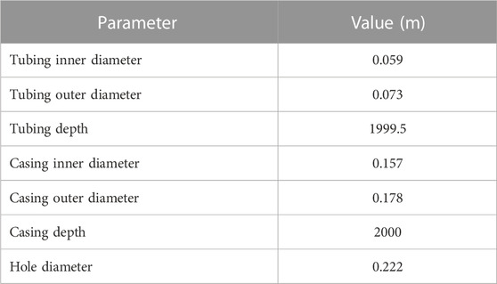
TABLE 1. Parameters for wellbore geometry modelling used in the simulations.
Figure 2 illustrates the model domain and boundary conditions used for our simulations. To optimize computational efficiency, we employed triangular-prism elements for the mesh type instead of pyramids. A finer mesh was implemented near the wellbore to accurately capture temperature changes. To test the mesh, we used two different mesh discratizations. A more refined mesh by a factor of 2 was generated and tested to ensure the final result was not affected by discrepancies. The difference in fluid exit temperature between the two simulations was found to be less than 1%, which can be considered negligible.
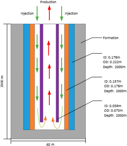
FIGURE 2. Model domain and the boundary conditions used for the simulations.
2.3 Material properties
The material parameters used in the simulations are listed in Table 2. The casing, cement, and reservoir are assumed to be isotropic and homogeneous.
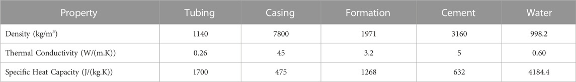
TABLE 2. Thermal properties of the materials in the wellbore and the reservoir.
2.4 Initial and boundary conditions
The simulation time is considered to be 10 years of operation, and the operational conditions of the circulating water are listed in Table 3. A prescribed constant far-field temperature is considered.
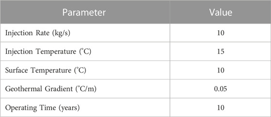
TABLE 3. Operational parameters used in the model.
2.5 Model verification
The model is verified against the analytical solution of Ramey’s wellbore heat transmission (Ramey, 1962). Ramey’s equation is widely employed to describe temperature distribution in wellbores and provides an excellent approximation compared to more rigorous methods (Hagoort, 2004). Assuming the flow inside the well is a single-phase flow, the analytical solution can be used to calculate the temperature distribution in a wellbore fluid as a function of wellbore depth and geothermal gradient:
where T(z,t) is the temperature of fluid in wellbore, Tinj is the injection temperature, and z is the depth of the fluid in wellbore. A is defined as
where W is the mass flow rate, kr is the thermal conductivity coefficient of the surrounding rock, and f(t) is a dimensionless time function representing the transient heat transfer to the formation, defined as
where rw is the radius of the well, and α is the thermal diffusivity of the rock.
2.6 Dimensionless parameters
To study the relative influence of different parameters on the production temperature and power generation in the presence of microannulus, a dimensionless analysis is conducted. This way the solution can be applied to a more generalized case under arbitrary conditions. To do so, we define the following dimensionless parameters, temperature (TD), depth (DD), power (PD), and microannulus severity (SD).
where
3 Results
To investigate the effect of microannulus in the exit temperature of the fluid and geothermal well power, a base case without microannulus was established, and a series of numerical simulations were conducted varying its severity. In the base case, after 10°years of operation, the circulating water reaches a peak temperature of 32.3°C at the bottom of the well and is produced at 28°C. The isosurface temperature plot of the wellbore demonstrates a cone-shaped distribution (Figure 3), illustrating the impact of geothermal heat extraction. This effect is more pronounced at greater depths as the difference between the temperature from the circulating water and the reservoir increases. It tends to smoothen as it moves further away from the wellbore.
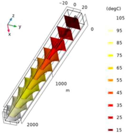
FIGURE 3. Isothermal surfaces around the wellbore after 10 years of operation.
First, the simulation is run by considering intact cement in the wellbore. The acquired result is used as a base case for verification and comparison with subsequent simulations where a microannulus is inserted between casing and cement, or between cement and the formation rock.
3.1 Verification
A comparison between the analytical and numerical results is shown in Figure 4. The results demonstrate good agreement between both models, with slight divergence as the well deepens. The difference is believed to be due to the cement not being considered in the analytical model, which would lead to lower temperatures. Therefore, the model can provide reliable estimation for long-term performance.
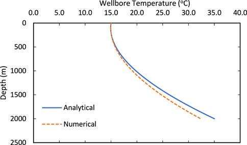
FIGURE 4. Comparison of the temperature distribution in the annulus between the analytical and numerical model.
3.2 Effects of cement-casing microannulus
Next, the simulations consider the wellbore with a microannulus encompassing the whole circumference around the outer casing, filled with drilling fluid. The size of the microannulus tested is between 0.1 and 0.5 mm and they are assumed to be constant throughout the well. Figure 5 illustrates the temperature of the circulating water as it is injected through the annulus and returns through the tubing.
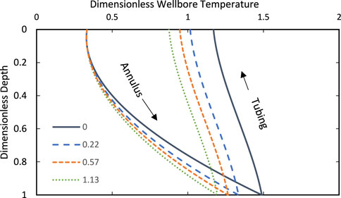
FIGURE 5. Temperature of the circulating water in the wellbore with different sizes of microannulus. The different lines correspond to the dimensionless microannulus severity. The output temperature decreases as the microannulus size increases.
In the tested cases, a 0.1 mm microannulus introduced between the casing and cement is sufficient to drop the exit temperature by 19%. In the most severe case, a 0.5 mm microannulus leads to a temperature drop larger than 25%. The presence of microannulus interrupts the heat flux which depends mainly on conduction between the formation and the wellbore. As its size increases, so does the obstruction. In order to test the sensitivity of our model to the choice of temperature gradient, we repeated the simulation using a more representative value of 30°C/km, which is typical in many oil and gas scenarios. This temperature gradient was applied uniformly throughout the model domain, and all other model parameters were kept constant. The results are shown in Figure 6.
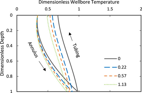
FIGURE 6. Example of temperature of the circulating water in the wellbore employing a temperature gradient of 30°C/km.
The findings indicate a considerable reduction in the exit temperature of the fluid compared to that of a geothermal well. Specifically, the analysis reveals that, in the tested cases, in the worst case the presence of microannulus can lead to a temperature drop of up to 18%.
3.3 Effects of cement-formation microannulus
To verify the effects of a microannulus between the cement and formation in the working fluid temperature, the same procedure is repeated with a small gap inserted between cement and formation. Figure 7 illustrates the temperature of the circulating water as it is injected through the annulus and returns through the tubing.
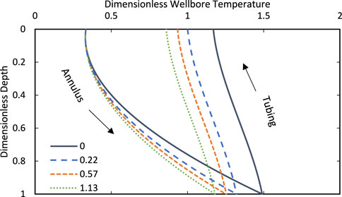
FIGURE 7. Temperature of the circulating water in the wellbore with different sizes of microannulus between cement and formation. The different lines correspond to the dimensionless microannulus severity. The output temperature decreases as the microannulus size increases.
The temperature drop is slightly higher than in the previous case, where a microannulus between casing and cement is present, in the simulated scenario. This is due to the higher contact area of the cement with the formation. In the most severe case (0.5 mm), the output temperature decreases by 26%.
3.4 Effects of microannulus severity
In extreme cases, the microannulus encompasses the full circumference of the wellbore. However, in most cases, only part or the cement is affected, as it can be seen in cement evaluation logs (Vrålstad and Skorpa, 2020; Santos and Dahi Taleghani, 2021). To evaluate the effect of the size of the microannulus on the bottomhole temperature, different degrees of severity were evaluated, ranging from 0 (no microannulus) to 1 (full circumference). Figure 8 shows microannuli with five different levels of circumferential coverage.
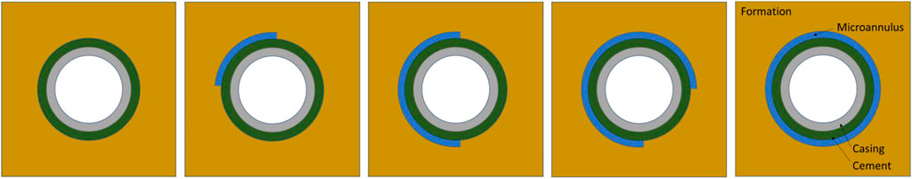
FIGURE 8. Different degrees of microannulus severity considered in the simulations.
Partial microannulus tends to occur with higher frequency in the wellbores and may not be discovered unless it propagates to the surface or cement evaluation logs are run. As demonstrated in Figure 9, The bottomhole temperature decreases linearly with the microannulus severity. Again, no significant difference is observed in the temperature drop caused by failure in the cement-casing and cement-formation interfaces. Different reasons such as imperfect mud displacement and remaining pockets of mud may initiate partial microannulus. Often, this issue has been reported in inclined wellbores.
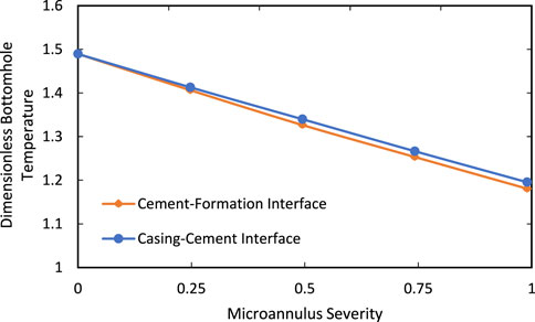
FIGURE 9. Comparison between bottomhole temperature for different microannulus severity after 10 years of production.
To further investigate the impact of microannulus on the bottomhole templerature, additional simulations were performed with the microannulus length varied across the wellbore and considering full circumference. Specifically, the length of the microannulus was increased gradually from the bottom of the wellbore towards the top (Figure 10).
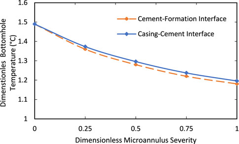
FIGURE 10. Comparison between bottomhole temperature for microannulus with varied length, after 10 years of production.
The results of these simulations indicated that the length of the microannulus had a significant impact on the fluid temperature in the bottomhole. For the same level of microannulus severity, the impact was more significant along the length of the wellbore than around its circumference. This was due to the higher temperatures observed at the bottom of the wellbore, which resulted in a greater temperature drop when microannulus was present.
3.5 Geothermal well power
The reduction in geothermal well power for both cases is illustrated in Figure 11. The introduction of a 0.5 mm microannulus between cement and formation can decrease thermal power by 37%. In the less severe case, a 0.1 mm microannulus between casing and cement reduces thermal power by about 18% in comparison with a wellbore absent of microannulus.
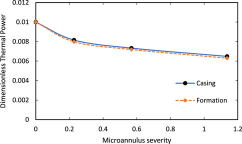
FIGURE 11. Comparison between thermal power produced by the wellbores with different sizes of microannulus after 10 years of production.
This work shows that even small gaps between cement interfaces can affect the circulating water temperature in closed-loop geothermal wells. This phenomenon is similar to temperature debonding in ground heat exchangers used with geothermal heat pumps (Philippacopoulos and Berndt, 2001). In particular, we found that the severity of the micro-annulus has a greater impact on the temperature of the produced fluid compared to other parameters. No significant difference was observed between the output temperature in the cement-casing and cement-formation interface. It is uncommon to have microannulus between both cement interfaces but well logs have demonstrated that long sections of the well can have partial microannulus, partial cement, or channels, which are even more critical. Therefore, careful cementing design and execution are of paramount importance to ensure the success of closed-loop geothermal systems.
A simple solution to avoid the formation of microannulus due to debonding between cement interfaces would be through additives. Enriching the cement with expansive additives (Fan et al., 2020; Santos et al., 2020), for example, can not only compensate for inherent cement shrinkage during hydration but may increase the bond strength between the interfaces. The bond strength is a key property to avoiding cement debonding and guaranteeing the maintenance of thermal power. It may also be increased with nano-engineered cement (Tabatabaei et al., 2020). A minimal concentration of nanoparticles has proven to improve cement bond strength and refine microstructural defects in the cement matrix.
More advanced designs suggest long horizontal wells, or use of high conductivity fluids and cement, to overcome the limitations of closed-loop wells in producing energy. But again, failure in cementing has shown it may compromise the whole project if not properly executed. As the microannulus is filled with fluid, heat transfer by convection can contribute to increasing heat flux at these interfaces. However, the fluid movement is minimal and was not considered in this work.
4 Conclusion
This study investigated the influence of microannulus filled with completion or formation fluid on the heat transfer in closed-loop geothermal systems. Numerical simulations with an application example demonstrate that the geothermal well power is significantly lower in the presence of microannulus between casing-cement and cement-formation interfaces. The microannulus causes temperature drop due to a reduction in heat flux, increasing the system’s resistance. The results suggest that the bond strength between cement interfaces needs to be taken into consideration in well design to guarantee the maintenance of thermal power.
Data availability statement
The original contributions presented in the study are included in the article/supplementary material, further inquiries can be directed to the corresponding author.
Author contributions
LS: writing, modelling, coding AT: review, advising, funding, conceptualization.
Conflict of interest
The authors declare that the research was conducted in the absence of any commercial or financial relationships that could be construed as a potential conflict of interest.
Publisher’s note
All claims expressed in this article are solely those of the authors and do not necessarily represent those of their affiliated organizations, or those of the publisher, the editors and the reviewers. Any product that may be evaluated in this article, or claim that may be made by its manufacturer, is not guaranteed or endorsed by the publisher.
References
Ahmadi, M., and Taleghani, A. D. (2017). “Thermoporoelastic analysis of a single-well closed-loop geothermal system,” in Poromechanics VI. Presented at the Sixth Biot Conference on Poromechanics, Paris, France, July 9–13, 2017 (American Society of Civil Engineers), 602–609.
Alimonti, C., Soldo, E., Bocchetti, D., and Berardi, D. (2018). The wellbore heat exchangers: A technical review. Renew. Energy 29, 353–381. doi:10.1016/j.renene.2018.02.055
Baumgarte, C., Thiercelin, M., and Klaus, D. (1999). Case studies of expanding cement to prevent microannular formation,” in In SPE annual technical conference and exhibition. Houston, Texas: OnePetro. doi:10.2118/56535-MS
Caulk, R. A., and Tomac, I. (2017). Reuse of abandoned oil and gas wells for geothermal energy production. Renew. Energy 112, 388–397. doi:10.1016/j.renene.2017.05.042
Chenevert, M. E., and Shrestha, B. (1987). Shrinkage properties of cement,” in In SPE Annual Technical Conference and Exhibition. Dallas, TX: OnePetro. doi:10.2118/56535-MS
Dahi Taleghani, A. (2013). An improved closed-loop heat extraction method from geothermal resources. J. Energy Resour. Technol. 135, 042904. doi:10.1115/1.4023175
Fan, J., Yang Santos, L., Dahi Taleghani, A., and Li, G. (2020). Stimuli-responsive petroleum cement composite with giant expansion and enhanced mechanical properties. Constr. Build. Mater. 259, 119783. doi:10.1016/j.conbuildmat.2020.119783
Ganvir, R. B., Walke, P. V., and Kriplani, V. M. (2017). Heat transfer characteristics in nanofluid—A review. Renew. Sustain. energy Rev. 75, 451–460. doi:10.1016/j.rser.2016.11.010
Goodwin, K. J., and Crook, R. J. (1992). Cement sheath stress failure. SPE Drill. Eng. 7 (04), 291–296. doi:10.2118/20453-PA
Hagoort, J. (2004). Ramey’s wellbore heat transmission revisited. SPE J. 9, 465–474. doi:10.2118/87305-pa
Higgins, B., Muir, J., Scherer, J., and Amaya, A. (2019). GreenFire energy closed-loop geothermal demonstration at the coso geothermal field. GRC Trans. 43, 14.
Hu, X., Banks, J., Wu, L., and Liu, W. V. (2020). Numerical modeling of a coaxial borehole heat exchanger to exploit geothermal energy from abandoned petroleum wells in Hinton, Alberta. Renew. Energy 148, 1110–1123. doi:10.1016/j.renene.2019.09.141
Kohl, T., Salton, M., and Rybach, L. (2000). Data analysis of the deep borehole heat exchanger plant Weissbad (Switzerland). Tohoku, Japan: Presented at the World Geothermal Congress, 7.
Liu, K., Gao, D., and Taleghani, A. D. (2018). Analysis on integrity of cement sheath in the vertical section of wells during hydraulic fracturing. J. Petroleum Sci. Eng. 168, 370–379. doi:10.1016/j.petrol.2018.05.016
Liu, S., and Taleghani, A. D. (2023). Factors affecting the efficiency of closed-loop geothermal wells. Appl. Therm. Eng. 222, 119947. doi:10.1016/j.applthermaleng.2022.119947
Philippacopoulos, A. J., and Berndt, M. L. (2001). Influence of debonding in ground heat exchangers used with geothermal heat pumps. Geothermics 30, 527–545. doi:10.1016/S0375-6505(01)00011-6
Ramey, H. J. (1962). Wellbore heat transmission. J. Petroleum Technol. 14, 427–435. doi:10.2118/96-PA
Rybach, L., Mégel, T., and Eugster, W. J. (2000). At what time scale are geothermal resources renewable? Presented at the world geothermal congress. Kyushu - Tohoku, Japan: International Geothermal Association, 7.
Santos, L., and Dahi Taleghani, A. (2021). On quantitative assessment of effective cement bonding to guarantee wellbore integrity. J. Energy Resour. Technol. 144, 013001. doi:10.1115/1.4050878
Santos, L., Taleghani, A. D., and Elsworth, D. (2022). Repurposing abandoned wells for geothermal energy: Current status and future prospects. Renew. Energy 194, 1288–1302. doi:10.1016/j.renene.2022.05.138
Santos, L., Taleghani, A. D., and Li, G. (2020). Smart expandable fiber additive to prevent formation of microannuli. SPE Drill Compl 13, 490–502. doi:10.2118/201100-PA
Song, X., Zheng, R., Li, R., Li, G., Sun, B., Shi, Y., et al. (2019). Study on thermal conductivity of cement with thermal conductive materials in geothermal well. Geothermics 81, 1–11. doi:10.1016/j.geothermics.2019.04.001
Tabatabaei, M., Taleghani, A. D., and Alem, N. (2020). Nanoengineering of cement using graphite platelets to refine inherent microstructural defects. Compos. Part B Eng. 202, 108277. doi:10.1016/j.compositesb.2020.108277
Keywords: microannulus, well integrity, heat transfer, geothermal wells, cement integrity
Citation: Santos L and Dahi Taleghani A (2023) Impact of microannulus on the efficiency of heat transfer in the bottomhole. Front. Energy Res. 11:1142662. doi: 10.3389/fenrg.2023.1142662
Received: 11 January 2023; Accepted: 25 April 2023;
Published: 09 May 2023.
Edited by:
Fuyong Wang, China University of Petroleum, Beijing, ChinaReviewed by:
Anozie Ebigbo, Helmut Schmidt University, GermanySheng Huang, Southwest Petroleum University, China
Copyright © 2023 Santos and Dahi Taleghani. This is an open-access article distributed under the terms of the Creative Commons Attribution License (CC BY). The use, distribution or reproduction in other forums is permitted, provided the original author(s) and the copyright owner(s) are credited and that the original publication in this journal is cited, in accordance with accepted academic practice. No use, distribution or reproduction is permitted which does not comply with these terms.
*Correspondence: Arash Dahi Taleghani, YXJhc2guZGFoaUBwc3UuZWR1