 Xingda Ji
 Tao Zou
 Xu Bai
 Xinbo Niu1
 Longbin Tao
- 1School of Naval Architecture and Ocean Engineering, Jiangsu University of Science and Technology, Zhenjiang, China
- 2Shandong Provincial Key Laboratory of Ocean Engineering, Ocean University of China, Qingdao, China
- 3Department of Naval Architecture, Ocean and Marine Engineering, University of Strathclyde, Glasgow, United Kingdom
Bolted ring flange connections are widely utilized in offshore wind turbines to connect steel tubular segments. After the massive production and installation of offshore wind turbines in the past decade, flatness divergence is regarded as one of the most important initial imperfections for the fatigue design of flange connections. Offshore wind turbines are subjected to wind, wave, and current loads. This initial imperfection may alter the structural response and accelerate the fatigue crack growth. This paper aims to analyse the impact of the initial flatness divergence on the structural response of flange connections and evaluate its consequences on fatigue damage. Two different offshore wind turbines with fixed foundations and floating foundations are modelled to simulate their global responses to environmental loads. Based on a superposition method, local finite-element models of flange connections are established with three types of flatness divergence. Using the same bolt pretension and external loads from global modelling, the impact of these geometric imperfections is further examined by comparing the structural responses of flanges under different radial and peripheral opening lengths. Then, the fatigue assessments on flange connections in both fixed wind turbines and floating wind turbines are conducted, and the impacts of initial flatness divergence on these two different wind turbines are analysed.
1 Introduction
During mass production and installations of offshore wind turbines (OWTs), in the wind industry, the bolted ring flange connections for assembling the OWT substructure and tubular steel towers have been widely used in the last few years (Pavlović et al., 2015a; Pavlović et al., 2015b). Throughout the service life of OWTs, the variable and cyclic loads from wind and waves sustained by wind turbine towers make them vulnerable to fatigue damage. Therefore, it has often been reported on fatigue cracks in wind turbine towers (Chou and Tu, 2011).
According to the location of openings, flatness divergence can be classified in flange-sided gapping, tower-sided gapping, and parallel gapping, as shown in Figure 1B. When preloading, these gaps close initially, and then, clamp solids emerge. Ji et al. (2021) and Long et al., 2021) established three types of tower flange gap to discuss the effects of the flange gap on the cumulative fatigue damage. They revealed that the special shape of the gap possesses a significant impact on fatigue damage. Jakubowski and Schmidt (2003) performed systematic experimental and numerical analyses on the influence of flange imperfections on the load transfer function (LTF), and the result showed that it was most difficult to close openings with parallel gaps, while the tower-sided gaps appeared to be less difficult. In contrast, the flange-sided gaps had a positive effect on the LTF, since it caused the resulting clamp force to move closely towards the tower wall and, thus, the resulting axis of external forces. This conclusion was also confirmed by Feldmann et al. (2011).
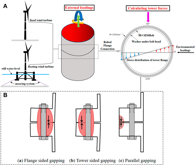
FIGURE 1. (A) Global responses of OWTs under the operating condition. (B) Clamp forces in imperfect bolted flanges.
In design practice, the LTF according to Schmidt–Neuper does not consider the various geometric flange imperfections shown in Figure 1B explicitly, but it covers a certain (but unknown) range of gap sizes and shapes implicitly. In order to account for these gap sizes and shapes, according to DNVGL-ST-0126 (DNVGL, 2018) and the DIN 18088-3 (DNVGL, 2019), the flatness divergence of one flange must be less than 2 mm in length over the entire flange circumference and less than 1 mm over a 30° segment after completing the tubular sections. However, Weijtjens et al. (2021) proposed that this requirement is semi-empirical and it did not consider those geometric imperfections explicitly. With bolted flange connections being widely used within OWT structures, which are quite large in diameter and thickness, it becomes additionally challenging to fulfil these requirements without a major effort during the OWT installations.
This research presents a numerical investigation of the effect of the initial flatness divergence on maximum stress and fatigue damage in the ring flange connections within fixed-bottom wind turbines (FBWTs) and floating offshore wind turbines (FOWTs). These two different OWTs are modelled to simulate their global responses to environmental loads in operating conditions, and external loads on the tower shell sections are calculated. Then, local finite-element models with the initial flatness divergence are applied to the same bolt pretension and external loads from global modelling. The local flanges’ responses are calculated based on LTFs. Finally, the fatigue damage of flange connections in both FBWTs and FOWTs is compared, and the impacts of the initial flatness divergence on these two different wind turbines are discussed.
2 Global responses of offshore wind turbines
In the past decades, significant research focused on the global response simulations of OWTs, as it was the foundation for any other further analysis. In this section, two different OWTs for both FBWTs and FOWTs are modelled to simulate their global responses to environmental loads using SESAM-SIMA software. Then, the cyclic loadings on the FOWT and FBWT tower shell sections under the operating condition are obtained. The workflow of the global responses of OWTs is shown in Figure 1A.
2.1 Description of offshore wind turbines
OWTs include FBWTs and FOWTs. FBWTs are usually operating in shallow water with a depth less than 60 m, and the foundations are inserted into the seabed. FBWTs are mainly subjected to environmental loads, such as wind and waves. Liu et al. (2010) considered that wind loads played a leading role in load combination for FBWTs’ tower. Different from FBWTs, FOWTs consist of a floating platform and restrained with various mooring systems that typically undergo displacement in the six degrees of freedom (Zou et al., 2021). Furthermore, they may undergo remarkable dynamic responses when operating in the hostile marine environment. FOWTs studied in this paper are the 5 MW OC4-DeepCWind semi-submersible wind turbine, as shown in Figure 2. The floater includes a centre column connecting the tower and three offset columns which are connected with the main column through a number of smaller pontoons and braces (details of the platform are given in Figure 2B). Three mooring lines are arranged symmetrically above the platform vertical axis with 120° between them. The radius to fairleads and anchors from the platform’s centreline is 40.868 m and 837.6 m, respectively. Each of the three lines has an unstretched length of 835.5 m with 0.0776 m diameter and an equivalent mass per unit length of 113.35 kg/m. The detailed layout and structural property are available in Robertson et al. (2014).
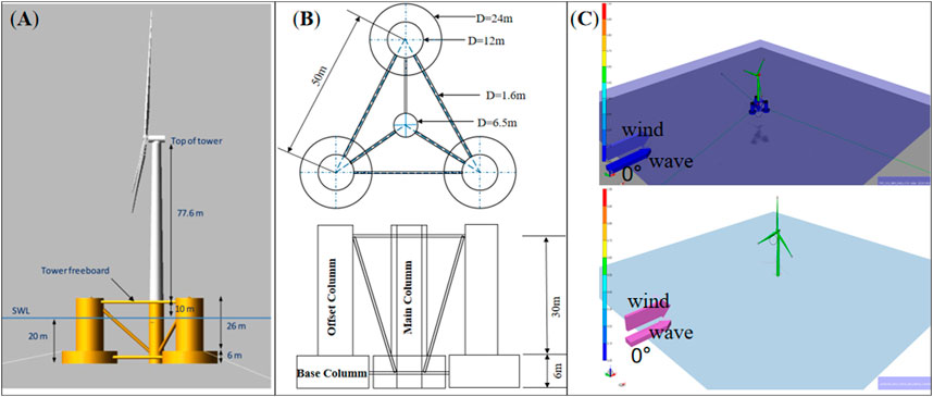
FIGURE 2. (A) Global view of the FOWT. (B) Details of the FOWTs’ substructure (Robertson et al., 2014). (C) Two different offshore wind turbines in SESAM-SIMA.
2.2 Calculating dynamic responses
OWTs have to resist winds, waves, and currents during the operation stage. Therefore, the environmental loads should be estimated before calculating the dynamic responses of OWTs (Hu et al., 2020). All these environmental loads induce an aerodynamic and hydrodynamic impact on the structures. Ye and Ji (2019) investigated the effects of both hydrodynamic and aerodynamic excitations which include current, wave, and wind excitations, as well as buoyant forces, along with the dynamic interaction between the drive–train system and tower structure on the dynamic response of the spar-type floating platform under different sea conditions. Chen and Basu (2018) considered the effects of current and wave–current interactions in the fatigue analysis of FOWTs. Their results showed that the current and the wave–current interaction could have significant influences on FOWT cable responses. Philippe et al. (2013) performed a coupled dynamic analysis of a floating wind turbine system to investigate the effect of the wave direction relative to wind on the wind turbine system. They considered that the natural modes of the tower system are excited differently regarding the wave’s direction.
In this research, wind and wave loads are considered as primary environmental external forces. Despite that the current may also affect the FOWTs’ motions, especially on supporting the structures of an extensive draft, it mainly acts on the mooring systems and contributes less to fatigue damage on the towers (Zou et al., 2022). Therefore, the current force is not discussed in this paper.
The external loads on the ring flange connections are calculated, as shown in Figure 2C. The wind and wave spectra are set as stationary uniform and JONSWAP for both FOWTs and FBWTs, respectively. The significant wave height is set as 3 m, spectral peak period is set as 10 s, and horizontal wind speed is set as 11.4 m/s.
The coupled global dynamic analysis carried out the time domain using the module SIMA in software package SESAM. The SESAM-SIMA calculates the internal forces and moments in the cross sections of the FOWTs’ and FBWTs’ tower under the same operation condition. Figure 3 shows the time series of the axial force and the bending moment in a cross section of the tower. The results show that the ranges of fluctuations in axial force and those of bending moment of the FOWTs’ towers increase compared to FBWTs’ towers, and FBWTs’ towers bear a greater axial force and bending moment compared to FOWTs’ towers under operating conditions. It is clearly observed that FOWTs’ substructures undergo oscillating motions in six degree of freedoms (DOFs) with larger magnitudes compared to fixed-bottom wind turbines. Their compliant foundations can reduce the counterforce around the tower and lower the stress in the structural response. Moreover, the substructure’s motions may influence the aerodynamic condition of the rotor, which makes the aerodynamic loadings on FOWTs much more complicated than those on FBWTs. de VaalHansen and Moan (2012) studied the effect of a periodic surge motion on the integrated loads and induced velocity on a wind turbine rotor through numerical simulations. Among all motions of the six DOFs, surge and pitch are regarded as the most important ones affecting the FOWTs’ aerodynamics (Bayati et al., 2016; Fang et al., 2020; Fang et al., 2021). Once the aerodynamic conditions are affected by the substructures’ motions, the external forces on the wind tower are also changed. Hence, it is necessary to consider the impact of FOWTs’ motions in the fatigue assessment.
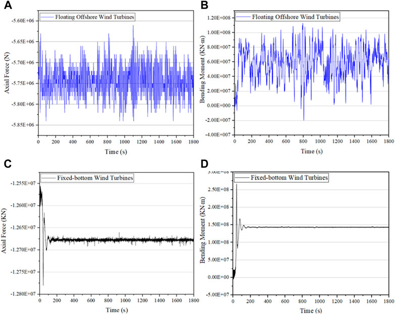
FIGURE 3. Time series of the axial force and the bending moment in cross sections of the OWTs’ tower. (A) Axial force above the FOWTs’ bolted connection. (B) Bending moment above the FOWTs’ bolted connection. (C) Axial force above the FBWTs’ bolted connection. (D) Bending moment above the FBWTs’ bolted connection.
3 Finite-element modelling of the connection
The finite-element method (FEM) model is established to analyse the stress distribution around flange connections. To simplify the modelling and minimize the computational cost, a segment of the connection that included one bolt and experienced the maximum load was isolated and modelled through ANSYS parametric design language (APDL) in this research. The following sections describe the structure of the FE models.
3.1 Material properties and geometry
The FE analysis was performed based on linear material models. The materials were modelled considering the steel’s elastic properties with linear behaviour until yielding. According to EN 1993-1-1 (EN, 1993-1-1Eurocode 3, 2005), the defined material was steel with a modulus of elasticity of 210 GPa and Poisson’s coefficient of 0.3. The materials of OWTs’ flanges and bolts are Q345E and 42CrMo. Their yield strengths are 345 MPa and 940 MPa.
The geometrical model studied consists of an upper flange, lower flange, washers, and bolt joining both parts, and the details of the cross section of the bolted connection is shown in Figure 4.
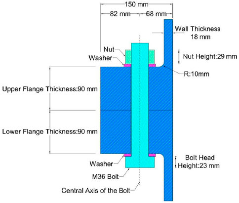
FIGURE 4. Cross section of the bolted connection.
3.2 Finite elements and the contact model
A finite-element model should not only have a low computational requirement but also reflect the key characteristics, such as irregular geometries and large deformations. In this study, SOLID186-type finite elements are used for the flange. SOLID186 is a 3D element with 20 nodes, and three degrees of freedom can accurately simulate irregular geometries and structural phenomena, namely, plasticity, creep, and large deformations, among others (System, 2005). The mesh density has an effect on finite-element results. A good grid layout is one of the key factors to improve the reliability of simulation when using the finite-element method for structure simulation. The coarse mesh density can decrease the computation time, but it may lead to a larger finite-element stress result that is not consistent with the reality. On the contrary, fine finite elements are used to improve the accuracy of the finite-element results with more computation time. Li et al. (2009) put forward the concept of key areas, and it was concluded that the precision of the calculation result of the whole finite-element model was determined by the meshing level of all the key areas in the finite-element model. In this section, the mesh density to ESIZE is set as 6 in the mesh tool initially, and Figure 5 shows that the stress value of the flange is too high. With the further use of small mesh density, the tendency of the flange stress is clearly shown approaching a stable value indicating that the mesh density of 0–1 is reasonable. In this paper, the mesh size was chosen to be a minimum of 0.9 mm and a maximum of 16 mm, with a total of 107,242 nodes and 14,997 elements. Figure 6 (left) shows a localised fine mesh around the areas with high stress concentration, while a relatively coarser mesh size is adopted for other areas. In addition, a pretension element (PRETS179 element in ANSYS) is used to apply the preload force on the bolts. The pretension elements are located in the middle of the bolt shaft. Then, ANSYS internally cuts the bolt into two parts and translates the cut planes axially so that the sum of the nodal reaction forces is equal to the preload force.
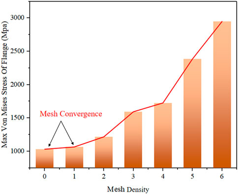
FIGURE 5. Maximum von Mises stress of the FOWTs’ flange under different mesh sizes.
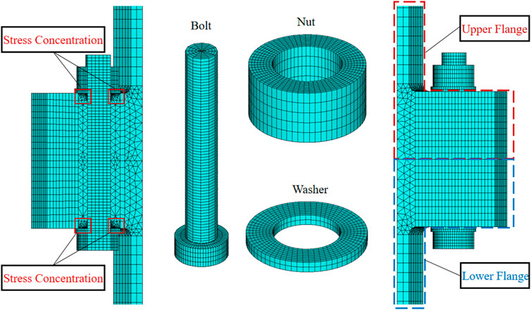
FIGURE 6. Finite-element model of the segment.
The local model was created with the configuration of the contacts between elements and the application of boundary conditions, which consisted of a frictional contact between the surface of the upper and lower flanges, washers and flanges, inner surface of flanges and the bolt shank, and a bonded contact between the surface of nuts and washers and inner surface of nuts and the bolt head. The friction coefficient applied was 0.15, adopting an augmented Lagrangian equation (Simo and Laursen, 1992).
3.3 Loads and boundary conditions
To assess the fatigue damage on OWTs’ tower flange, the calculation of the cyclic load amplitudes ΔFb requires the approximation of the load transfer between the tower shell loads and the resulting bolt force inside the flange. According to the current design standards, this is performed using a load transfer function (LTF). Figure 7 (left) schematically shows the LTF Fb (Z), with the external load Z acting in the tower shell on the abscissa and the bolt load Fb on the ordinate. Due to the eccentric load introduction and the presence of the preload Fp of the bolts, the LTF is non-linear.
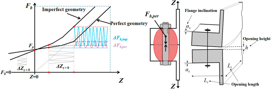
FIGURE 7. Schematic illustration of the load transfer function under perfect and imperfect geometrical flange conditions (left); centric clamp solid due to the preload depicted in red (middle); and the detailed configuration of flatness divergence (right).
For the reduction of fatigue loads, bolt pretension Fp is necessary for structural integrity. The preload Fp is induced via either torque-controlled tightening or direct tensioning methods. With the broadly used torque-controlled tightening procedure, the bolt shall be preloaded up to the reduced nominal preload, Fp,c* = 0.7Rp0.2∙Asp, where Rp0.2 is the material plastic strain limit and Asp is the stress area of the bolt thread.
Under perfect geometric conditions, as the surface pressure between the upper and lower flange increases due to the tightening, a clamp solid emerges centrically around the longitudinal bolt axis as a counterpart of the preload, as shown in Figure 7 (middle). With the clamp solid distributed symmetrically around the bolt axis, external forces acting in the tower shell first diminish the resulting clamp force, which reduces cyclic bolt forces ΔFb. However, under imperfect flatness divergence conditions, the flange contact surface is not ideally plane due to a flange inclination αs, a flange opening length Li, and a flange opening height h, which is shown in Figure 7 (right). The two flange parts may open, and the clamp solid may develop eccentrically from the bolt’s longitudinal axis.
The flange connections are mainly subjected to external loads, such as moments, pressure, and shear. The axial stress applied to the upper tower flange shell sections is calculated as follows (Eq. 1). The shear is neglected due to its minor contribution to fatigue damage.
Here, Z is the external load, β is the angle between the location of the bolt and the x-axis, Faxial is the maximum axial force (plotted in Figure 3), My is the y-axis bending moment (plotted in Figure 3) above the horizontal axis perpendicular to the wind direction, At is the area of the tower shell, R is the radius of the flange, and N is the number of high strength bolts installed in the flange (plotted in Figure 1).
A preload force of 510 KN is applied on the bolt in order to simulate the tightening of the bolt (Ajaei and Soyoz, 2020). A uniform tensile stress of 42.2 MPa and compressive stress of 43.5 MPa are applied to FOWTs’ tower shell sections, respectively. FBWTs’ tower shell sections are applied to the tensile stress of 92.1 MPa and the compressive stress of 94.3 MPa. All degrees of freedom at the bottom of the tower shell are fixed, and symmetric boundary conditions were applied.
Li and Ren (2013) calculated the maximum stress of the 1.5 MW wind turbine tower under the operation condition, and the result showed that the maximum stress under the operating condition is 71 MPa. Ajaei and Soyoz (2020) calculated the external loads using TurbSim software and applied the vertical traction time series (the maximum traction is 44 MPa) to the upper edge of the tower wall and different bolt preloads in order to investigate the effect of a bolt preload level on fatigue damage in eccentrically loaded bolts of ring flange connections. Alonso-Martinez et al. (2019) applied a 519.91-KN preload force on the bolt, 32.57 KN compressive load, and 18.37 KN tensile load on the flange wall segment in order to study the behaviour of the flange and analyse the cause of the collapse.
4 Finite-element analysis results and discussion
The structural responses of local finite-element models of flange connections with a perfect model and three types of flatness divergence under different radial and peripheral opening lengths (details of the three types of flatness divergence are shown in Figure 8) are simulated by applying the same bolt pretension and external loads obtained from global modelling. The finite-element analyses are performed to investigate the effects of the gap size on stress ranges experienced by the FOWTs’ flanges and bolts. Compared to the perfect condition (Figure 9), the tendency of bolt and flange stress increment under the flatness divergence is shown in Section 4.1. Finally, the impacts of the initial flatness divergence on these two different wind turbines are shown in Section 4.2.
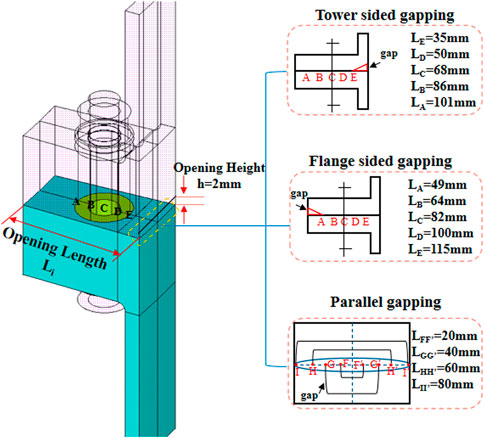
FIGURE 8. Details of the imperfect model.
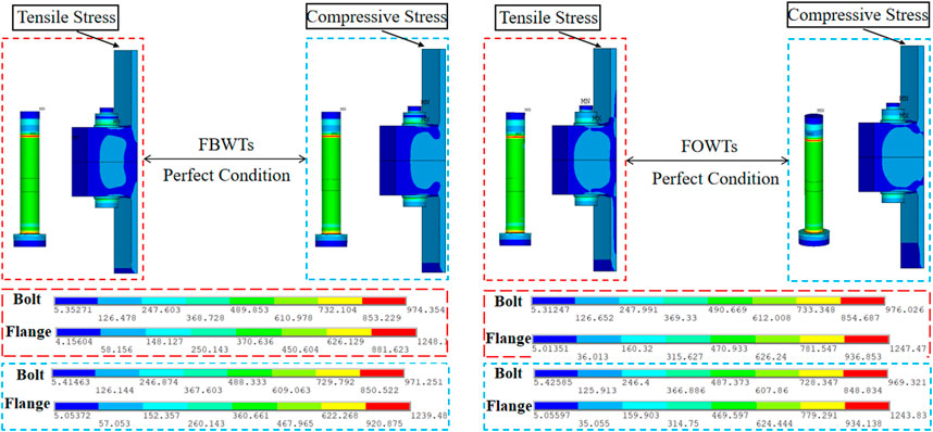
FIGURE 9. Von Mises stress state of the OWTs’ tower flange under the perfect condition.
4.1 Effect of gap length on bolt and flange stress
Figure 9 shows that bolts’ and flanges’ stress concentrations occur at the bolt head under the perfect condition. Figure 10 shows that imperfect models’ stress concentration mainly occurs at the bolt head and the centre of the bolt shank. With the increase in opening length, the locations of stress concentrations are transferred from the bolt head to the centre of the bolt shank. For flanges with flange-sided gapping and tower-sided gapping (Figure 11 (1) (2)), stress concentrations initially occur at the bolt head and transfer to the opening gaps with the increase in opening length. For parallel gapping, a three-sector local finite-element model is established, as the contact surface between the two flange parts opens completely in the middle and the middle bolt loses its preload completely. Hence, the cyclic loadings on the FOWTs’ tower shells are mainly sustained by other two bolts, and the locations of stress concentrations occurring in the bolt head and gaps are shown in Figure 11 (3). These locations may play a critical role in fatigue assessments.
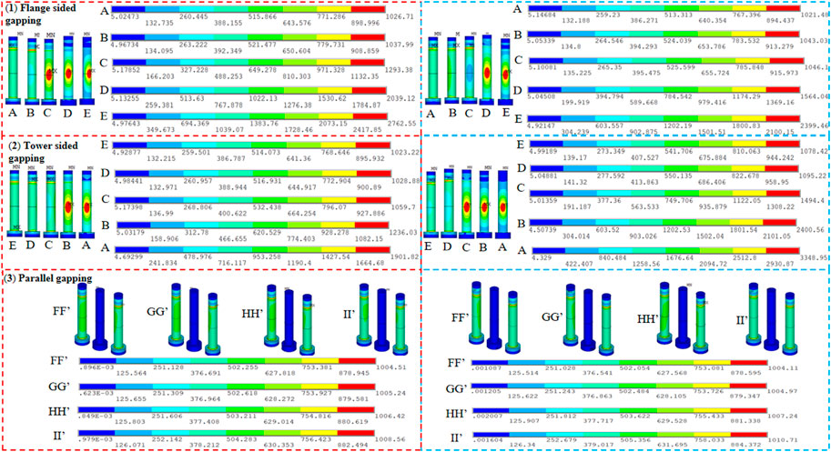
FIGURE 10. Von Mises stress state of the FOWTs’ tower bolts under the initial flatness divergence when subjected to tensile (left) and compressive stresses (right) (details of the location of openings are given in Figure 8).
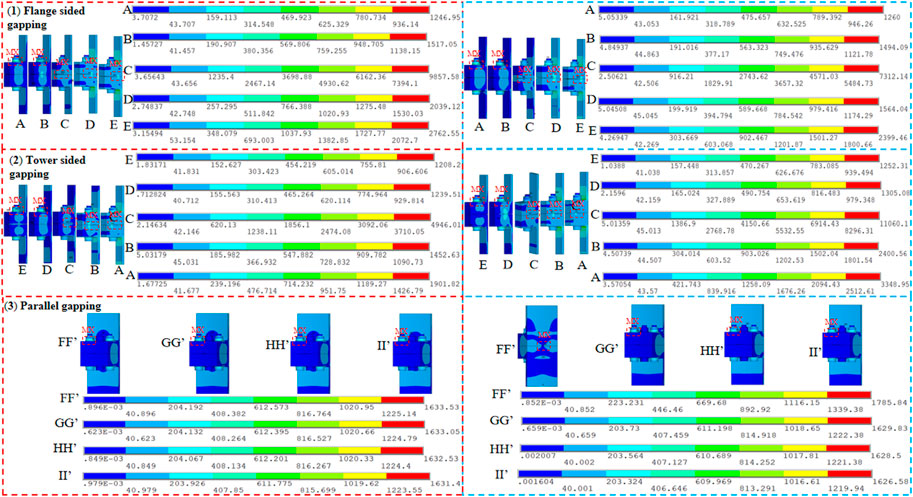
FIGURE 11. Von Mises stress state of the FOWTs’ tower flanges under initial flatness divergence when subjected to tensile (left) and compressive stresses (right) (details of the location of openings are given in Figure 8).
Figure 12 schematically shows the variation tendency of the bolt and flange stress increment under flatness divergence. It is evident that the magnitude of the bolt and flange stress increased considerably when the opening length increases. The main findings are drawn as follows:
1. When the tower shell is subjected to tensile stress, bolt and flange stresses significantly increase in flange-sided gapping compared to the other two types of flatness divergence. The maximum stress of bolts is 2763 MPa (Figure 10), where (1 with a maximum flange opening length, and the stress increases to 1787 MPa (Figure 12A) for flange-sided gapping compared to the perfect condition (Figure 9, right). The bolt stress increment is about 5% for tensile when the gap length is 49 mm (point A in Figure 8), and the bolt stress increment is about 183% for tensile when the gap length is 115 mm (point E in Figure 8) for flange-sided gapping. For flanges, the maximum stress is 9858 MPa [Figure 11 (1)] when the location of openings occurs in the centre of the bolt shank, i.e., point C (gap length 82 mm) in Figure 8, and the stress increases to 8610 MPa for flange-sided gapping (flange stress increment is about 690%) compared to the perfect condition (Figure 9, right).
2. The bolts and flanges are more sensitive to tower-sided gapping when the tower shell sections are subjected to compressive stress. Compared to the perfect condition shown in Figure 9 (right), the increase of bolts’ stress is 2380 MPa (Figure 12B), and the flanges’ increase is 9816 MPa (Figure 12B). The bolt stress increment is about 11% for compression when the gap length is 35 mm (point E in Figure 8), and the bolt stress increment is about 246% for compression when the gap length is 101 mm (point A in Figure 8) for tower-sided gapping. For flanges, the maximum stress increment is about 789% when the location of openings occurs in the centre of the bolt shank, i.e., point C (gap length 68 mm) in Figure 8 compared to the perfect condition (Figure 9, right).
3. When the openings become larger, the contact surfaces of the upper and lower flanges are finally completely separated. The flange connection appears less sensitive to parallel gapping; this is due to the fact that the bolt in the middle segment has failed, and the cyclic loadings are mainly sustained by flanges. The increase of flanges is 541 MPa (Figure 12C) compared to the perfect condition. These tendencies indicate that initial flatness divergences can result in a significant increase of stresses, which should be taken into account in fatigue assessments.
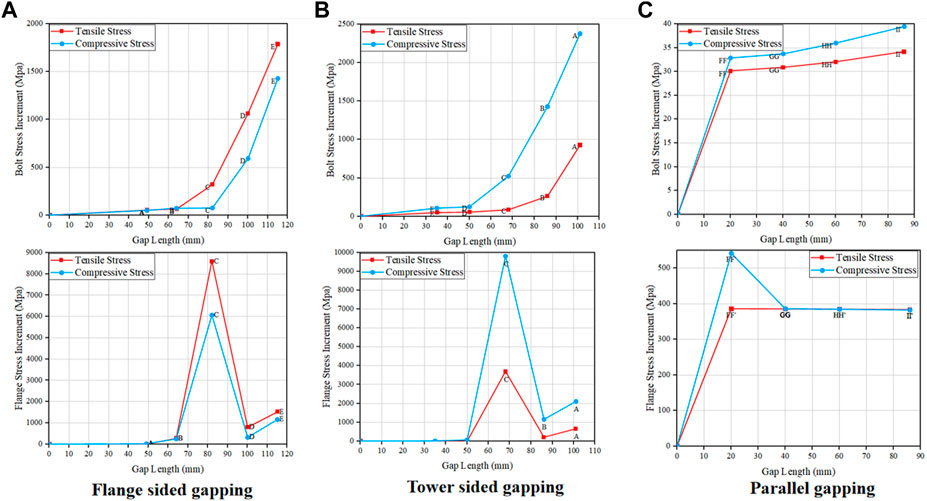
FIGURE 12. Stress increment of the FOWTs’ tower bolts and flanges under flatness divergence. (A) Under flange sided gapping. (B) Under tower sided gapping. (C) Under parallel gapping (details of the location of openings are given in Figure 8).
Figures 9–11 show that the stress of both the bolt and the flange exceeds the materials’ yield strength. In the case of the model with flatness divergence, the structure is subjected to deformation or even destruction. The plastic deformation may occur at this bolt, and it will lose its resistance against external forces. The external force on this bolt will be transferred to the surrounding bolts. In this paper, the structure response after plastic deformation is not considered. Instead, the influence of the imperfections on the structural stress is mainly discussed. When using the finite-element method for meshing, improper meshing may lead to stress concentration. The non-convergence of stress can result in an extremely higher stress compared to the real structural stress (as shown in Figure 6). Therefore, the stress extrapolation method is generally used in finite-element calculation. Alonso-Martinez et al. (2019) applied a 520 KN preload force on the M36 bolt and calculated the maximum von Mises stress of local finite-element models of flange connections with the perfect model by ANSYS Workbench. The result showed that the maximum stress of the flange was about 4700 MPa. It also exceeds the yield strength of the materials. Ji et al., 2021 and Long et al. (2021) established three types of tower flange gap to discuss the effects of the flange gap on the bolts stress. The result revealed that the bolt stress was more sensitive to flange-sided gapping when the tower shell was subjected to tensile stress, and the bolt stress was more sensitive to tower-sided gapping when the tower shell was subjected to compressive stress. This result is consistent with the findings in Figure 12.
4.2 Effect of gap sizes on different OWTs’ bolts
The stress difference of bolts is not significant between FOWTs and FBWTs at the beginning. When the location of openings occurs at the centre of the bolt shank, i.e., point C in Figure 8, the bolt stress of FBWTs is observed to be significantly affected by the tower-sided gapping and flange-sided gapping compared to FOWTs (as shown in Figure 13). This trend is due to external forces Z acting on the FBWTs’ tower shell larger than those on the FOWTs’ tower shell. This large external force Z leads to a higher bolt load Fb to some extent. With the openings becoming large until the flange contact surface completely opens, the bolts cannot exert an adequate clamping force to keep the joint together. Hence, parallel gapping has a weak influence in the middle bolt but has a greater impact on the neighbouring bolts for both FOWTs and FBWTs.
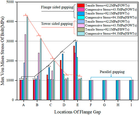
FIGURE 13. Maximum von Mises stress of the FOWTs’ and FBWTs’ tower bolts under flatness divergence (details of the location of openings are given in Figure 8).
For the tower-sided gapping condition, the maximum stress of FBWTs’ bolts is about 1200 MPa and the maximum stress of FOWTs’ bolts is about 1800 MPa when the tower shell is applied with tensile stress. In addition, when the tower shell is subjected to compressive stress, the maximum stress of FBWTs’ bolts is about 4300 MPa and the maximum stress of FOWTs’ bolts is about 3300 MPa. For the flange-sided gapping condition, the maximum stress of FBWTs’ bolts is about 3000 MPa and the maximum stress of FOWTs’ bolts is about 2700 MPa when the tower shell is applied with tensile stress. When the tower shell is subjected to compressive stress, the maximum stress of FBWTs’ bolts is about 2200 MPa and the maximum stress of FOWTs’ bolts is about 2400 MPa.
5 Discussion
As can be observed, these geometric imperfections with the initial flatness divergence have significant effects on both flange and bolt stresses. Typical load transfer and potential reasons for the impacts between flanges and bolts are as follows:
a) For ring flanges, stress concentrations occur in the bolt head and the location of geometric imperfections. When geometric imperfections occur in the bolt centre, the flange stress may have a sharp rise due to the bolt failure.
b) For bolts, stress concentrations often occur centrically around the longitudinal bolt axis and bolt head. With the increase in opening length, the locations of stress concentrations are transferred from the bolt head to the centre of the bolt shank.
c) For offshore wind turbines, the case with tower-sided gapping has a more significant impact on FBWTs’ bolts, while FOWTs’ bolts are more sensitive to flange-sided gapping.
6 Fatigue analysis and results
Fatigue damage is a cumulative process caused by cyclic loads (Zou and Kaminski, 2020). Initial imperfections are one of the most critical factors for fatigue strength in bolted connections, except for a vulnerable material, cyclic tensile loads, and higher stress levels (Mehmanparast et al., 2020). This study focuses on the impact of flatness divergences on bolted connections’ fatigue damage, including flange-sided gapping, tower-sided gapping, and parallel gapping. Therefore, it is assumed to have a 20-year design life of bolts, i.e., 1e7 number of cycles, and conducts the fatigue assessments for flange connections in both fixed wind turbines and floating wind turbines based on the accumulation of fatigue damage computed with nominal stresses and S–N curves.
6.1 Global–local methodology
In this section, a global–local methodology of the fatigue assessment procedure is utilized. This method emphasises the theoretical concepts associated with the modal superposition and fatigue analysis. A workflow for the global–local fatigue assessment methodology is shown in Figure 14. It introduces two different phases of analysis from the global to the local scale with increasing details of geometrical, material, and contact properties. The two phases of fatigue analysis are systematized as follows. In the first phase, a global approach based on the accumulation of damage computed with nominal stresses and S–N curves is introduced. The adopted global numerical model should be accurate enough to obtain nominal stresses to be used as input loading for the linear damage accumulation method. Since the available S–N curves with nominal stress may not properly reflect the local geometrical and material characteristics of critical details, a conservative S–N curve for the fatigue resistance is, thus, considered. Based on the fatigue analysis result, the critical details should be identified, which require a more refined assessment by implementing local scale models. Then, in the second phase, submodelling techniques leveraged by modal superposition concepts are used to accurately evaluate local fatigue damage.
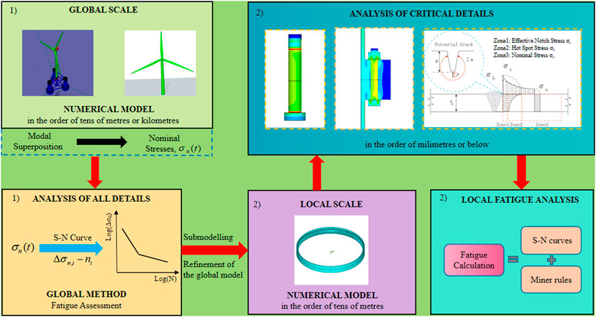
FIGURE 14. Workflow of the global–local fatigue assessment methodology for offshore wind turbines.
6.2 S–N curves and Miner’s rule
For an offshore structure design, fatigue damage is usually calculated based on the S–N curve approach. The fatigue resistance is represented by S–N curves (Gao et al., 2021). S–N curves define the relationships between the stress ranges and the numbers of cycles to failure in those stress ranges. GL 2010 (Wind guideline, 2010) provides S–N curves for different structural materials, including a bolt with a diameter larger than 30 mm (M36 bolts) used in the bolted connection, which is considered in this paper. The basic design of the S–N curve is given as
where
Miner’s rule for damage summation described in DNVGL-RP-0005: 2014-06 (DNVGL-RP-0005:2014-06, 2014) and given in Eq. 3 is used in this paper to estimate fatigue damage.
where ni is the number of the existing stress cycles in each range and Ni is the number of stress cycles in each range, which can cause fatigue failure. It is usually assumed that failure occurs when the damage index D reaches 1.0.
6.3 Fatigue results
Figure 15A shows the fatigue damage on FOWTs’ and FBWTs’ bolts with a maximum flange opening length within 20 years. It is observed that the existence of flatness divergence in bolted flange connection increases the fatigue damage severely. Moreover, it makes a significant impact to consider the different types of flatness divergence in fatigue assessments, especially under tower-sided gapping and flange-sided gapping conditions. On the contrary, the fatigue damage of the middle bolt appears not so sensitive to parallel gapping which may significantly affect the neighbouring bolts. Compared to FOWTs, FBWTs’ bolts are more vulnerable to fatigue damage due to higher external loads and stress range (the stress range of bolts is calculated by stress extrapolation method), as shown in Figure 15B. The flexible foundations of FOWTs can reduce the counterforce around the tower against the environmental loads and result in lower structural responses. The fatigue damage of FBWTs’ bolts is 0.86, which is about 1% larger than that of FOWTs, which is 0.85, when the tower is subjected to tensile stress and the fatigue damage of FOWTs’ bolts is 0.65, which is about 2% larger than that of FBWTs, which is 0.63, when the tower shell is subjected to compressive stress for flange-sided gapping. Furthermore, the fatigue damage of FOWTs’ bolts is 0.5, which is about 2% larger than that of FBWTs, which is 0.48, when the tower shell section is subjected to tensile stress and the fatigue damage of FBWTs’ bolts is 1.16, which is about 18% larger than that of FOWTs, which is 0.98, when the tower shell is subjected to compressive stress for tower-sided gapping. Hence, more attention to FBWTs’ bolts with tower-sided gapping under the compressive stress is necessary during the design process for safe operation.
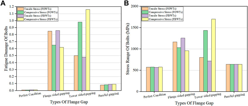
FIGURE 15. (A) Fatigue damage of OWTs’ tower bolts under the initial flatness divergence. (B) Stress range of OWTs’ tower bolts under the initial flatness divergence.
7 Conclusion
This paper analysed the impact of the initial flatness divergence on the structural response of flange connections in OWTs and evaluated its consequences on fatigue damage.
The effects of different opening lengths on flanges’ and bolts’ stresses were compared by establishing local finite element models with three types of flatness divergence. The fatigue assessments for flange connections in both fixed wind turbines and floating wind turbines were conducted. The impacts of the initial flatness divergence on these two different wind turbines were compared. According to the results of the finite-element analysis, the main conclusions were drawn as follows:
1. The ranges of force fluctuations in the FOWTs’ towers are larger than in FBWTs. FOWTs’ substructures were not fixed to the seabed; they had oscillating motions in the six DOFs and would experience larger motions than the bottom-fixed wind turbines. The flexible foundations of FOWTs could reduce the counterforce around the tower against the environmental loads, resulting in lower structural responses. The maximum tensile stress of the FBWTs’ tower shell can be 50% larger than that of FOWTs, and the maximum compressive stress of the FBWTs’ tower shell is shown to be 51% larger than that of FOWTs.
2. The stress of bolted flange connection can increase significantly with the increase in the opening length, and stress concentrations may occur in the bolt head, the centre of the bolt shank, and gaps. Thus, particular attention should be paid to these locations for safe operation. For the flange-sided gapping, the stress of bolts and flanges increase significantly when the tensile stress is applied to the tower shell. Compared to the perfect condition, the flange-sided gapping is markedly increased and demonstrated for the maximum bolt stress and the maximum flange stress. For the tower-sided gapping, the compressive stress has a significant influence on the bolt and flange with significant increases in the maximum bolt stress and the maximum flange stress, respectively, compared to the perfect condition. The bolt stress increases by 40 MPa and the flange stress increases by 541 MPa, which is not sensitive to parallel gapping.
3. The very significant negative effect of the initial flatness divergence could be confirmed based on fatigue analysis. The local finite-element model with tower-sided gapping and flange-sided gapping demonstrated a significant increase in the fatigue damage of bolts compared to parallel gapping. For the flange-sided gapping, the fatigue damage of the FOWTs and FBWTs is approximately the same. For the tower-sided gapping, however, the fatigue damage of the FOWTs is markedly lower than that of FBWTs. Compared with parallel gapping, the fatigue damage of FBWTs is almost the same as that of FOWTs.
Data availability statement
The raw data supporting the conclusion of this article will be made available by the authors, without undue reservation.
Author contributions
XJ: conceptualisation, software, investigation, formal analysis, and writing—original draft. TZ: first corresponding author, methodology, writing—review and editing, and validation. XB: second corresponding author and writing—review and editing. XN: picture making. LT: writing—review and editing. All authors contributed to the article and approved the submitted version.
Funding
This research was supported by the Shandong Provincial Key Laboratory of Ocean Engineering under grant no. kloe202010, the Natural Science Foundation of Jiangsu Province (Grant Nos. BK20220654 and BK20211342), and the National Natural Science Foundation of China (Grant No. 42276225). The authors would like to thank the Key R and D Projects in Guangdong Province (No. 2020B1111500001) for their financial support.
Conflict of interest
The authors declare that the research was conducted in the absence of any commercial or financial relationships that could be construed as a potential conflict of interest.
Publisher’s note
All claims expressed in this article are solely those of the authors and do not necessarily represent those of their affiliated organizations, or those of the publisher, the editors, and the reviewers. Any product that may be evaluated in this article, or claim that may be made by its manufacturer, is not guaranteed or endorsed by the publisher.
References
Ajaei, B. B., and Soyoz, S. (2020). Effects of preload deficiency on fatigue demands of wind turbine tower bolts. J. Constr. Steel Res. 166, 105933. doi:10.1016/j.jcsr.2020.105933
Alonso-Martinez, M., Adam, J. M., Felipe, P., Alvarez-Rabanal, J., and Diaza, J. D. C. (2019). Wind turbine tower collapse due to flange failure: FEM and DOE analyses. Eng. Fail. Anal. 104, 932–949. doi:10.1016/j.engfailanal.2019.06.045
Bayati, I., Belloli, M., Bernini, L., and Zasso, A. (2016). Wind tunnel validation of AeroDyn within LIFES50+ project: Imposed surge and pitch tests. J. Phys. Conf. Ser. 753, 092001. doi:10.1088/1742-6596/753/9/092001
Chen, L., and Basu, B. (2018). Fatigue load estimation of a spar-type floating offshore wind turbine considering wave-current interactions. Int. J. Fatig. 116, 421–428. doi:10.1016/j.ijfatigue.2018.06.002
Chou, J. S., and Tu, W. T. (2011). Failure analysis and risk management of a collapsed large wind turbine tower. Eng. Fail. Anal. 18 (1), 295–313. doi:10.1016/j.engfailanal.2010.09.008
de VaalHansen, J. B. M. O. L., and Moan, T. (2012). Effect of wind turbine surge motion on rotor thrust and induced velocity. Wind Energy 17 (1), 105–121. doi:10.1002/we.1562
DNVGL (2019). Design standard - structures for wind turbines and platforms – Part 3: Steel structures. DIN.
EN 1993-1-1Eurocode 3 (2005). Design of steel structures - Part 1–1: General rules and rules for buildings. Brussels, Belgium: European Committee for Standardization CEN.
Fang, Y., Duan, L., Han, Z., Zhao, Y., and Yang, H. (2020). Numerical analysis of aerodynamic performance of a floating offshore wind turbine under pitch motion. Energy 192, 116621. doi:10.1016/j.energy.2019.116621
Fang, Y., Li, G., Duan, L., Han, Z., and Zha, Y. (2021). Effect of surge motion on rotor aerodynamics and wake characteristics of a floating horizontal-axis wind turbine. Energy 218, 119519. doi:10.1016/j.energy.2020.119519
Feldmann, M., Naumes, J., and Pak, D. (2011). Zum Last-Verformungsverhalten von Schrauben in vorgespannten Ringflanschverbindungen mit überbrückten Klaffungen im Hinblick auf die Ermüdungsvorhersage. Stahlbau 80 (1), 21–29. doi:10.1002/stab.201001386
Gao, J., Ma, X., Dong, G., Chen, H., Liu, Q., and Zang, J. (2021). Investigation on the effects of Bragg reflection on harbor oscillations. Coast. Eng. 170, 103977. doi:10.1016/j.coastaleng.2021.103977
Hu, Y., Yang, J., Baniotopoulos, C., Wang, X., and Deng, X. (2020). Dynamic analysis of offshore steel wind turbine towers subjected to wind, wave and current loading during construction. Ocean. Eng. 216, 108084. doi:10.1016/j.oceaneng.2020.108084
Jakubowski, A., and Schmidt, H. (2003). Experimentelle Untersuchungen an vorgespannten Ringflanschstößen mit Imperfektionen. Stahlbau 72 (3), 188–196. doi:10.1002/stab.200300660
Ji, L., Long, K., Gu, C., and Chen, Z. (2021). Effects of tower flange warping on bolt fatigue. Acta Energiae Solaris Sin. 42, 10. doi:10.19912/j.0254-0096.tynxb.2019-1017
Li, T., Zuo, Z., and Liao, R. (2009). Meshing method of high precision FEM in structural simulations. Chin. J. Mech. Eng. 45 (6), 304. doi:10.3901/jme.2009.06.304
Li, X., and Ren, L. (2013). Finite element analysis of wind turbine tower. Appl. Mech. Mater. 351-352, 825–828. doi:10.4028/www.scientific.net/amm.351-352.825
Liu, W., Tang, B., and Jiang, Y. (2010). Status and problems of wind turbine structural health monitoring techniques in China. Renew. Energy 35, 1414–1418. doi:10.1016/j.renene.2010.01.006
Long, K., Ding, W., Chen, Z., Li, Y., and Nouman, S. (2021). Effects analysis of flange gap on bolt fatigue damage for wind turbine tower. Acta Energiae Solaris Sin. 42, 12. doi:10.19912/j.0254-0096.tynxb.2019-1467
Mehmanparast, A., Lotfian, S., and Vipin, S. P. (2020). A review of challenges and opportunities associated with bolted flange connections in the offshore wind industry. Metals 10 (6), 732. doi:10.3390/met10060732
Pavlović, M., Heistermann, C., Veljković, M., Pak, D., Feldmann, M., Rebelo, C., et al. (2015). Connections in towers for wind converters, part I: Evaluation of down-scaled experiments. J. Constr. Steel Res. 115, 445–457. doi:10.1016/j.jcsr.2015.09.002
Pavlović, M., Heistermann, C., Veljković, M., Pak, D., Feldmann, M., Rebelo, C., et al. (2015). Friction connection vs. ring flange connection in steel towers for wind converters. Eng. Struct. 98, 151–162. doi:10.1016/j.engstruct.2015.04.026
Philippe, M., Babarit, A., and Ferrant, P. (2013). Modes of response of an offshore wind turbine with directional wind and waves. Renew. Energy 49, 151–155. doi:10.1016/j.renene.2012.01.042
Robertson, A., Jonkman, J., Masciola, M., and Song, H. (2014). Definition of the semi-submersible floating system for phase II of OC4. Denver: National Renewable Energy Laboratory NREL.
Simo, J. C., and Laursen, T. A. (1992). An augmented Lagrangian treatment of contact problems involving friction. Comput. Struct. 42, 97–116. doi:10.1016/0045-7949(92)90540-g
Weijtjens, W., Stang, A., Devriendt, C., and Schaumann, P. (2021). Bolted ring flanges in offshore-wind support structures - in-situ validation of load-transfer behaviour. J. Constr. Steel Res. 176, 106361. doi:10.1016/j.jcsr.2020.106361
Wind guideline, G. L. (2010). Guideline for the certification of wind turbine[S]. Hamburg: Germanischer Lloyd WindEnergie GmbH.
Ye, K., and Ji, J. (2019). Current, wave, wind and interaction induced dynamic response of a 5MW spar-type offshore direct-drive wind turbine. Eng. Struct. 178, 395–409. doi:10.1016/j.engstruct.2018.10.023
Zou, T., and Kaminski, M. (2020). Projection and detection of climate change impact on fatigue damage of offshore floating structures operating in three offshore oil fields of the North Sea. Ocean. Dyn. 70, 1339–1354. doi:10.1007/s10236-020-01396-y
Zou, T., Liu, W., Li, M., and Tao, L. (2021). “Fatigue assessment on reverse–balanced flange connections in offshore floating wind turbine towers. 41st international conference on ocean, offshore & artic engineering,” in Proceedings of the 41st international conference on ocean, offshore & artic engineering. doi:10.1115/OMAE2021-64973
Keywords: offshore wind turbines, fatigue assessment, flatness divergence, imperfection, flange connections
Citation: Ji X, Zou T, Bai X, Niu X and Tao L (2023) Fatigue assessment of flange connections in offshore wind turbines under the initial flatness divergence. Front. Energy Res. 11:1127957. doi: 10.3389/fenrg.2023.1127957
Received: 20 December 2022; Accepted: 09 February 2023;
Published: 27 February 2023.
Edited by:
Kok Hoe Wong, University of Southampton Malaysia, MalaysiaCopyright © 2023 Ji, Zou, Bai, Niu and Tao. This is an open-access article distributed under the terms of the Creative Commons Attribution License (CC BY). The use, distribution or reproduction in other forums is permitted, provided the original author(s) and the copyright owner(s) are credited and that the original publication in this journal is cited, in accordance with accepted academic practice. No use, distribution or reproduction is permitted which does not comply with these terms.
*Correspondence: Tao Zou, dHpvdUBqdXN0LmVkdS5jbg==; Xu Bai, YmFpeHVAanVzdC5lZHUuY24=