 Shengjie Fu1,2
 Liangzhu Zhu
- 1College of Materials Science and Engineering, Zhejiang University of Technology, Hangzhou, China
- 2Key Laboratory of Advanced Fuel Cells and Electrolyzers Technology of Zhejiang Province, Ningbo Institute of Materials Technology and Engineering, Chinese Academy of Sciences, Ningbo, China
Metal-supported solid oxide fuel cells (MS-SOFCs) have attracted increasing attention due to their superior mechanical strength, relatively low material cost, and capability of fast thermal cycling, as compared to the conventional all-ceramic solid oxide fuel cell. However, fabrication of MS-SOFCs still remains challenging. This study reports a cost-effective powder metallurgical manufacturing route for producing MS-SOFCs. Stainless steel 430L (SS430L) powder is selected for producing the metal support due to its relatively low cost and good thermal expansion compatibility. MS-SOFC button cells with the SS430L/YSZ|Ni/YSZ|YSZ|LSCF structure were successfully prepared by co-sintering and ultrasonic pyrolytic spraying. We found that the trace oxygen level in the dilute H2/Ar gas mixture could play a drastic role in laboratory sintering of the SS430L support; local oxygen control is essential, particularly to avoid Cr oxidation. The addition of no more than 10% YSZ as a second phase to SS430L substantially minimized over-sintering of the SS430L support, leading to a more porous metallic-type substrate, while the electrical conductivity and thermal expansion were not much affected. The fabricated MS-SOFC button cells with the SS430L/YSZ|Ni/YSZ|YSZ|LSCF structure delivered a maximum power density of 180 mW cm-2 at 800°C with an open-circuit voltage of 1.13 V, using dry hydrogen as the fuel and ambient air as an oxidant. A cell tested at 750°C showed relatively good stability for a period of 140 h. While the performance still needs further optimization, the high OCV and good stability indicated that the reported powder metallurgy route is a promising method, and the relevant experimental details, particularly on producing metallic and oxidation-free porous supports, are critical for the preparation of MS-SOFCs.
1 Introduction
The solid oxide fuel cell (SOFC) and its reversible application as the solid oxide electrolysis cell (SOEC) have been the subject of continuous research for decades due to their high efficiency, flexibility in fuel types, and ability of using non-precious metal catalysts (Hauch, Küngas et al., 2020; Clark, Malerød-Fjeld et al., 2022; Xu, Guo et al., 2022; Zarabi Golkhatmi, Asghar et al., 2022). Metal-supported solid oxide fuel cells (MS-SOFCs) using elevated-temperature-resistant metal alloys, such as stainless steel (SS), have gained much attention for their superior mechanical shock strength and high thermal cycling performance (Tucker 2010; Krishnan 2017; Udomsilp, Rechberger et al., 2020). Due to the near perfect matching in thermal expansion coefficients, certain types of SS such as ferritic stainless steel can bond well with ceramic SOFC electrolyte materials such as YSZ. These advantages and properties make MS-SOFCs more suitable for mobile applications such as in automobiles and ships than conventional SOFCs using YSZ or Ni–YSZ as the support. Also, most importantly, most SS types are much cheaper than either YSZ or Ni. For example, the cost of Ni is about 9 times that of the 400-series SS, while the cost of YSZ with rare earth yttrium doping is typically even an order of magnitude higher than that of Ni (Tucker 2010). A huge reduction in the material cost can play a significant role in SOFC development since in general the cost of current SOFC products is still far from satisfactory, with targets of about $225/kWe stack costs and $900/kWe system cost for SOFC applications set by the U.S. Department of Energy years ago (Krishnan 2017). Thus, replacing conventional support materials in SOFCs by SS is economically favorable and attractive.
So far, the one that is the closest to commercial application among all the current MS-SOFC techniques is developed by Ceres Power with a trademark of SteelCell®. Unlike conventional approaches of making continuous and random micro-gas openings for fuels to diffuse into and for H2O to diffuse out of the support while under the power generation model, SteelCell® utilizes laser drilling to directly get straight gas openings through dense SS substrates. Functional layers and electrolytes are then applied by various film deposition techniques (Oishi, Rudkin et al., 2002; Steele, Atkinson et al., 2004; Krishnan 2017). Other MS-SOFC approaches more or less rely on conventional ceramic or metal processes such as tape casting, screen printing, thermal spray/plasma spray deposition, and sputtering deposition to prepare porous metal supports, electrode functional layers, and electrolyte layers in sequence (Krishnan 2017; Tucker 2017; Udomsilp, Rechberger et al., 2020). One example is from a group of German/Austrian collaboration projects including the German Aerospace Center (DLR), Plansee, and AVL List GmbH. Their MS-SOFCs utilized a ferritic Fe–Cr alloy with 26% Cr as the porous substrate; the cells delivered a power density of 455 mW cm-2 at 823°C at 0.7°V (Rüttinger, Mücke et al., 2011; Krishnan 2017). These cells have applied a diffusion barrier layer (DBL) deposited on the substrate to prevent Fe and Ni counter diffusion between the anode and substrate by air plasma spray (APS), and they have a dual-layer electrolyte—a slightly porous YSZ layer with a GDC thin electrolyte layers—prepared by PVD sputtering. When tested as auxiliary power units (APUs) and fed with a simulated diesel reformate gas containing 50% N2, 15% H2, 14% CO, 11% H2O, and 10% CO2, a standard MS-SOFC achieved a power density of 200 mW cm-2 at 0.7 V at stack operating temperatures of about 750°C and a fuel utilization of 80% (Franco, Haydn et al., 2013; Haydn, Ortner et al., 2014). This is an encouraging result since an advantageous application of MS-SOFCs as compared with other fuel cells, such as proton exchange membrane fuel cells (PEMFCs), is the ability of using carbonaceous fuels such as diesel. Another typical MS-SOFC fabrication process is using tape casting either by making asymmetrical anode support-type MS-SOFCs such as by the Danish Technological University (DTU) group (Blennow, Hjelm et al., 2011; Nielsen, Persson et al., 2018) or by hot laminating two relatively thick SS green tapes sandwiching a thin electrolyte green tape followed by the infiltration of cathode and anode materials (Tucker 2017; Dogdibegovic, Wang et al., 2019). Note that the DTU group’s results of the simulated diesel reformate gas with 0.65 ppm sulfur led to high degradation rates (McKenna, Christiansen et al., 2013). A few comprehensive review articles, such as Tucker (2010) and Krishnan (2017), are suggested herein for more progress information on MS-SOFCs.
Neither the costs of large-scale laser drilling nor conventional approaches of making MS-SOFCs are sufficiently low or close to mature; therefore, continuous efforts are still needed for MS-SOFC development. Among all the technical barriers, the preparation of oxidation-free SS metal supports with suitable pore openings, densification of the electrolyte layer onto a metal support, and application of the cathode onto sintered SS support half-cells (cells with only one electrode and electrolyte layer) without re-oxidation of the metal support are a few critical technical challenges.
In this study, we report on detailed processes of solving the aforementioned issues. First, we report fabrication of oxidation-free SS metal supports with the integration of a simple and effective laboratory-friendly gas purification method, which is particularly important for using dilute H2 in inert gas mixture, since quality control may vary depending on gas suppliers. Second, we report on the controlling of suitable porosity and pore openings in the SS metal support through the addition of pore formers and additional small amounts of non-metal reactive or immiscible second phase to stop the over-growth of SS grains and reduction of porosity. Third, we report on how to deposit a thin layer of the cathode via the in situ thermal spray coating process, which otherwise needs a secondary sintering step as in conventional SOFC fabrication. Finally, we report on our cell performance under typical testing conditions.
2 Experimental methods
2.1 Preparation of materials and single cells
The porous metal support of MS-SOFCs was prepared by powder metallurgy using SS430L powder (Guangzhou Youyan Powder Material Technology Co., Ltd.), a type of pore-forming agent (Starch, Tianjing Hengxing Chemical Preparation Co., Ltd.), and a type of non-metal reactive oxide as a second-phase agent, which in this study is YSZ (8 mol% Y2O3-stabilized zirconia, Qingdao Terio Corporation). Table 1 provides the composition of SS430L powder. Figure 1A shows the morphology of the as-received powder. For the fabrication of the porous metal support, powders of SS430L and YSZ were first placed in a stainless steel jar with stainless steel balls, and the balls were milled for 24 h with ethanol. The slurry was then continuously stirred on a hot plate at 80°C to evaporate the residual ethanol. Starch was then added to the dried powder and dry-milled for another 2 h to get the SS430L/YSZ/starch raw support mixture. For making metal supports, 1.5 g of the raw support mixture was placed into a cylindrical mold of 22 mm diameter and dry-pressed under 210 MPa.
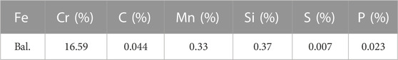
TABLE 1. Composition of SS430L ferritic stainless steel powder.
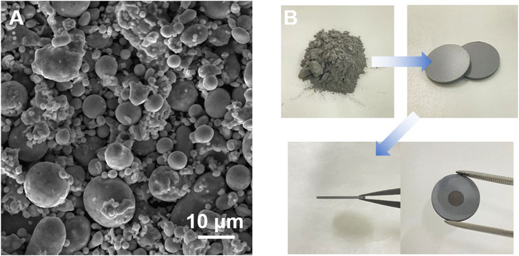
FIGURE 1. SEM image showing the as-received SS430L powder (A) and photographs showing the brief summary of the cell fabrication process (B).
The aforementioned pressed green pellets were placed into an alumina crucible and heated at 400°C for 2 h in a muffle furnace in air to burn off pore-formers and were then pre-sintered inside a controlled atmosphere furnace at 1170°C for 2 h under the ultra-high-purity 5% H2 in Ar gas mixture. We noticed that the oxygen level in the H2/Ar mixture provided by a local gas supplier was higher than expected, which is to be discussed further; therefore, we added a desiccator and commercial oxygen purification column (filled with metallic palladium on alumina support) along the gas line to decrease the oxygen level and added a titanium film of dimension 40 × 200 × 0.1 mm close to sintered substrates as oxidation sacrifice to further lower down the oxygen level. These additional in situ gas purification steps were later proved to be very efficient and critical with a reasonably low cost to prepare high-quality oxidation-free porous SS430L supports, particularly for the laboratory-scale production, which otherwise will need high-quality control from gas suppliers. Pre-sintered metal supports were then hand-printed with the NiO–YSZ functional layer paste and screen-printed YSZ electrolyte layer, respectively, and further dried in an oven at 80°C for 4 h to remove volatiles. The resulting green half-cells were first heated at 450°C for 3 h, followed by sintering at 1400°C for 3 h under the 2.5% H2 in Ar gas mixture. The flow rate of the gas mixture was 500 mL min-1. Similar to the pre-sintering step, a desiccator, oxygen purification column along the gas line, and titanium film were applied to further decrease the oxygen level in the gas mixture during this step. After this step, the half-cells were ready for cathode application.
A conventional SOFC cathode, such as LSCF (La0.6Sr0.4Co0.2Fe0.8O3–δ), typically requires sintering at greater than 1000°C under an oxidizing atmosphere to form a robust thin cathode layer. For all-ceramic SOFC half-cells, this process is relatively simple. However, this requirement brings challenges for cathode sintering on top of MS-SOFC half-cells. Sintering at higher than 1000°C should be avoided for the porous metal support, while the cathode has to be sintered under an oxidizing atmosphere. We solved this issue by using an in situ thermal spray coating process, which is similar to a previously developed method (Zhang, Zhu et al., 2016). The process directly coated a thin layer of the cathode onto a half-cell without the need of performing high-temperature sintering. In brief, the cathode precursor solution with a concentration of 0.01 M was prepared by dissolving La(NO3)3·6H2O, Sr(NO3)2, Co(NO3)2·6H2O, and Fe(NO3)3·9H2O (all with 99.9% purity from Aladdin) in DI water. The half-cell samples were placed on a hot plate at 200°C, and the solution was deposited uniformly on the electrolyte’s surface using a 1-mm-diameter ultrasonic nozzle. After deposition, the thin film cathode was heated in air at 400°C for 2 h before cell testing; this forms a thin cathode layer with sufficient mechanical strength. The crystallization of the cathode phase was expected during the heating up and initial testing of the cells at above 700°C, as to be discussed further. A brief summary of the cell fabrication process is presented in Figure 1B.
For thermal expansion measurements, SS430L/YSZ metal powder with and without a pore-former was dry-pressed into bar samples and sintered using the process similar to the preparation of the SS support. For electrical measurements, SS430L/YSZ in different ratios were cold-isostatic-pressed at 350 MPa and sintered at 1400°C for 3 h under the 5% H2 in Ar gas mixture.
For analysis of the structure of SS430L/YSZ support metal powders at different proportions were placed into a cylindrical mold of 10 mm diameter and dry-pressed under 250 MPa and sintered at 1400°C for 3 h under the 5% H2 in Ar gas mixture. These samples were polished with the 600–2000 mesh sandpaper and 0.5–2.5 μm alumina powder.
2.2 Testing and characterization
Testing of the MS-SOFC button cells was performed in a tube furnace using an alumina tube with open ends. The porous Ag slurry was used as the cell collector, and silver wires were bonded by a silver paste (DAD-87, Shanghai Research Institute of Synthetic Resins) to electrodes as current and potential sensing leads. The cells were then mounted onto one end of the alumina tube, sealed with the Ceramabond 552-VFG (Aremco) paste and thoroughly dried in an oven at 270°C for 2 h. The cell was heated to 700°C at a heating rate of 4°C min−1 with 100 ml min-1 of 10% H2 in N2 gas mixture fed to the anode, while the cathode was exposed to air. The temperature was maintained for 3 h after reaching 700°C to sinter the LSCF cathode in situ, while the anode was protected in a reducing atmosphere. Electrochemical impedance spectroscopy (EIS) and Current-Voltage (I-V) tests of the cells were performed under dry H2 fuel at 700–800°C, and all impedance measurements were made under the open-circuit voltage.
The surface and cross section of the samples were examined using a scanning electron microscope (SEM) equipped with a backscattered electron (BSE) detector with the FEI Quanta FEG-250 model. Phase identification was performed using X-ray diffraction (XRD, D8 DISCOVER). Electrical conductivity for SS430L/YSZ composites was measured by the four-probe DC method using Ivium in a reducing atmosphere (5% H2/Ar) at 400–800°C. The selected samples of SS430L/YSZ (SS430L:YSZ = 9:1) were analyzed for their thermal expansion coefficients at 25–800°C under nitrogen or air using a thermal expansion coefficient tester.
3 Results and discussion
3.1 Effects of the sintering atmosphere and oxygen level on SS430L support fabrication
We found that oxygen level control is critical in sintering SS supports and MS-SOFCs. The trace amounts of oxygen in a low concentration of H2 (typically less than 5%) in Ar gas mixture may easily lead to the oxidation of SS when sintering porous metal supports at high temperatures. In general, we noticed that while sintered products were not quite sensitive to small deviations of H2, the products were quite sensitive to a small change in the oxygen level (ppm). At the beginning of sintering the porous metal support used for this study, we observed the formation of a greenish-oxide layer on the surface of an SS support after sintering at 1350°C using a commercially available high-purity H2–Ar gas mixture (Figure 2A). Figure 2B shows the XRD spectrum of the surface of this sample, indicating the Cr2O3 phase in the matrix in addition to having an α-Fe(Cr) solid solution. The XRD result agrees with the observed greenish color, meaning that our gas initially did not have a sufficiently low oxygen level. Efforts were thus focused on lowering the oxygen level.
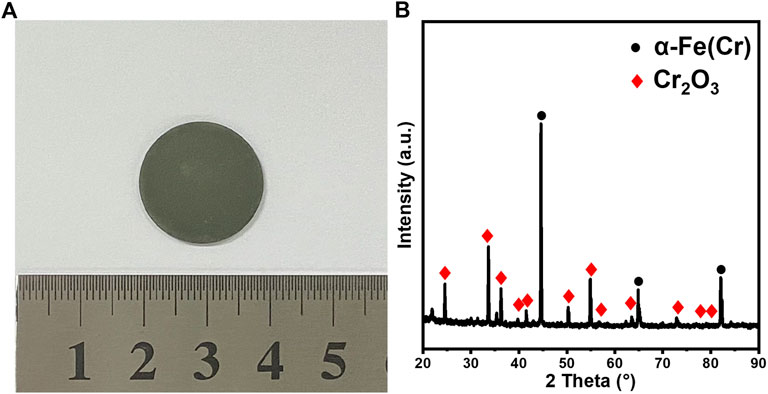
FIGURE 2. SS430L porous support after being sintered at 1350°C for 3 h under the raw and non-purified 5% H2/Ar gas mixture: (A) optical image; (B) XRD pattern. The raw materials contain 24 wt.% starch (based on SS430L).
In order to minimize the oxidation of sintered SS supports in reducing the gas at higher temperatures, the gas mixture was treated before entering the controlled atmosphere furnace by a low-cost commercially available gas purification tube to capture oxygen in the raw atmosphere. In addition, thin titanium sheets were placed in the crucible next to SS supports or cells inside the furnace as the in situ oxygen adsorbent during sintering to further remove trace oxygen levels and protect metal substrates from being oxidized. After implementing the gas purification steps, a typical sintered SS sample is shown in Figure 3A, which has a light-gray to metallic-like surface. XRD analysis in Figure 3B shows that the surface only contains α-Fe(Cr) solid solution. The differences thus prove the effectiveness of the proposed additional gas purification process.
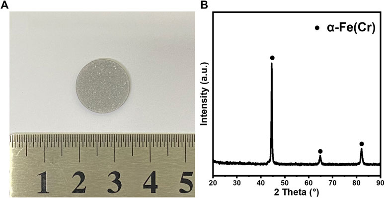
FIGURE 3. SS430L porous support after being sintered at 1350°C for 3 h under the purified 5% H2/Ar gas mixture: (A) optical images; (B) XRD pattern. The raw materials contain 24 wt.% starch (based on SS430L).
The effect of adding the oxygen-absorbent agent (titanium in the aforementioned case) to control the oxygen level is further strengthened by adding a few similarly prepared SS samples along the gas inlet direction in the same crucible under the same sintering conditions with nearby titanium placements. Figures 4A,B show the schematic of sintering conditions and photographs of samples after sintering, respectively. As can be seen, significant chromium oxidation was observed only in the sample closest to the gas inlet, and the oxidation states dramatically decreased with the increasing distance from the inlet. Since the gas flow rate is very low (0.2 L/min) for a relatively large tube diameter (50 mm) and the temperature is relatively high (1350°C), the effect of temperature variation was not expected to play a role. It is clear that the first SS sample along the gas flow direction also reacted with trace oxygen in the gas stream, leaving a local low-oxygen-containing gas atmosphere flowing to the rest of the samples. While controlling the oxygen level can have various approaches in the industrial process, the systematic investigation on adding oxygen purification columns and metal-absorbent agents will be performed in our future studies; our results suggest that adding these two steps are beneficial to producing nearly oxidation-free supports for laboratory-scale MS-SOFC production for research in a relatively cost-effective way.
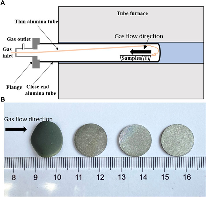
FIGURE 4. Illustration of the samples sintered under the purified 5% H2/Ar gas mixture at 1350°C for 3 h: (A) schematic showing the gas flow direction and the relevant position between titanium films and samples; (B) photographs showing the samples after sintering. The raw materials contain 24 wt.% starch (based on SS430L). Note that other than in this test, other samples in this study are sintered in an alumina tube with two open ends, where titanium films were also added in the same sample crucible.
The aforementioned results and importance of paying attention to even ppm levels of oxygen in the dilute H2/inert gas mixture during the sintering of porous SS in MS-SOFCs are better explained in Figure 5, which compares the thermodynamics of the oxidation of Fe, Cr, Ni, and Ti metals and reduction of their corresponding common oxides Fe2O3, Cr2O3, NiO, and TiO2, respectively. Among these four metals, Fe and Cr are the major metal elements in the SS support. Ni is an ingredient for SS, although its content is almost neglected in the 400 series SS as compared with Fe and Cr. The plots in Figure 5 are similar to that of the well-known Ellingham diagram frequently used in metallurgical engineering. Note that for simplicity, we directly take Fe2O3 instead of considering other intermediate iron oxides such as FeO and Fe3O4 as used in the Ellingham diagram. As shown in Figure 5A, from room temperature to the typical MS-SOFC working temperature (indicated by the Tw Zone) and then to the sintering temperature (indicated by the Ts Zone), all these metal elements tend to be easily oxidized under the oxidizing atmosphere with no presence of H2. Thermodynamics tells us that the lower the position of the line, the higher the tendency to form oxides, and thus it becomes more stable once in the oxide form. Therefore, at higher temperatures, the Ti sheet near the samples will not only consume a large portion of remaining trace amounts of oxygen impurity in the gas stream but also compete with Fe and Cr in the SS substrate, and thus it helps in lowering the local oxygen level so that the SS substrate is protected. In the case of SS substrates near the gas inlet, Cr acts similarly to Ti due to a much lower dissociation oxygen partial pressure (Figure 5B).
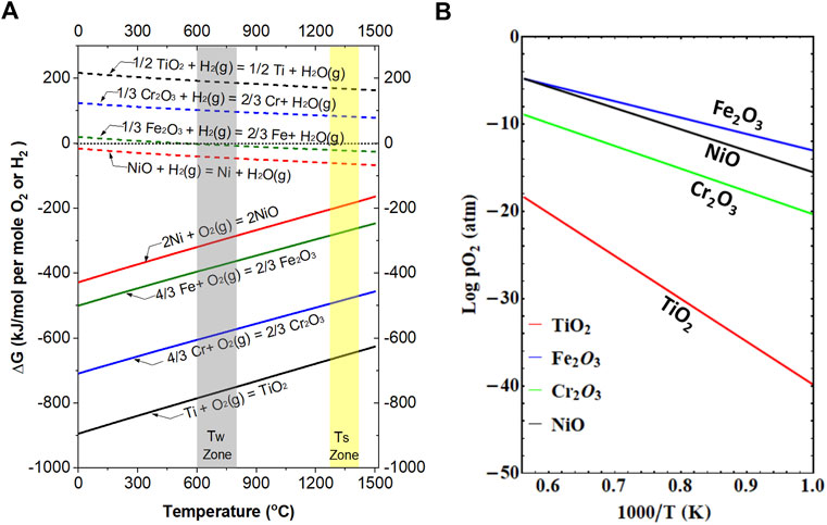
FIGURE 5. (A) Thermodynamics of the oxidation of Fe, Cr, Ni, and Ti metals and the reduction of their corresponding common oxides Fe2O3, Cr2O3, NiO, and TiO2, respectively. (B) Dissociation oxygen pressure for Fe2O3, Cr2O3, NiO, and TiO2.
On the other hand, if the oxygen level is not too low, for example, more than 100 ppm, all the four elements may be oxidized if no reducing gas is present, such as under the flow of Ar gas with no removal of trace oxygen. However, if a small amount of H2 is added to the same Ar gas stream, even though it may only be a few percent, its concentration is still orders of magnitude higher than the oxygen content; Fe2O3 and NiO can be reduced back to Fe and Ni, respectively, as shown by the H2 reduction lines in Figure 5A. TiO2 and Cr2O3, however, are not easily reducible under this condition due to their positive Gibbs free energy change in the whole temperature range. Therefore, our results and calculations from Figure 5 clearly prove the importance of controlling the oxygen level in the H2/Ar gas mixture to avoid or minimize Cr2O3 formation during SS sintering.
3.2 Effects of adding a low-solubility second phase on SS430L support property
While precise control of the oxygen level may be the most critical step to ensure an oxidation-free metal frame for high-temperature (>1300°C) co-sintering of the SS support with on-top ceramic layers, we found that adding a low-solubility second phase into the SS support is equivalently beneficial to creating gas channels within the metal frame by stopping significant SS grain growth so that the gas channels do not collapse. Although 400 series SS such as 430 have similar thermal expansion as that of ionic conductors such as YSZ and can be well bonded to each other after sintering, their sintering behaviors are quite different due to their very unmatching melting temperatures, which greatly affects their sintering kinetics and density of the sintered body at the same sintering temperature.
In order to facilitate mass transport, thus minimizing concentration polarization, pore-formers are usually added to conventional anode support sintering. Although it is still possible to co-sinter porous SS substrates (by adding pore-formers) and ceramic electrolyte layers at these high temperatures, the large melting temperature differences may easily lead to over-sintering of the SS substrate, i.e., significant grain growth of SS particles, while ensuring a dense ceramic layer. For metals, the sintering temperature is suggested in the range from 65% to 80% of the melting temperature. For ceramics, the optimum sintering temperatures are suggested from above 50% to 80% of the melting temperature to promote material transport, particularly to remove open pores. The melting temperature of NiO, YSZ, and GDC are, respectively, around 1950°C, 2700°C, and 2400°C. Therefore, the optimum sintering temperature for SS430L should be lower than 1200°C to eliminate significant grain growth. However, for the YSZ-type electrolyte containing mostly zirconia, the minimum sintering temperature, by taking 50% of the melting temperature (2700°C), should be around 1350°C without the addition of the sintering additive. This temperature is also typically used for sintering conventional SOFCs. Apparently, there seems to be a difference of at least 150°C in the optimum sintering temperature between SS and YSZ materials. Since a dense electrolyte layer is the priority of MS-SOFCs, very often a sintering temperature that matches YSZ materials was used in reported MS-SOFC studies (Dogdibegovic, Wang et al., 2019; Welander, Hu et al., 2022). Our sintering results suggest that depending on the particle size of raw materials, such high-temperature co-sintering may easily lead to drastic grain growth even with the addition of pore-formers as discussed in the following paragraph.
Figures 6A,B show the surface of a SS430L substrate with the addition of 24 wt.% of starch pore-formers sintered at 1400°C under purified 5% H2/Ar for 3 h. Significant grain growth is observed as compared with raw particles shown in Figure 1A and the original particle size distribution. Grains of size larger than 100 μm are seen, and all the grains are tightly packed with nearly no open pores. This type of substrate will block fuel transport, making it unsuitable for MS-SOFCs. Since decreasing the co-sintering temperature will lead to other issues, we solved this issue by borrowing the second-phase sintering mechanism or the Zener theory known for many decades in polycrystalline material sintering (Anderson, Grest et al., 1989; Chang, Feng et al., 2009). Basically, the concept is to use a second phase, which is non-soluble or has low solubility in primary grains (SS grains in this study), to slow down or block the surface or grain boundary diffusion of atoms so that the primary grains become somehow isolated or surrounded by a thin second-phase matrix.
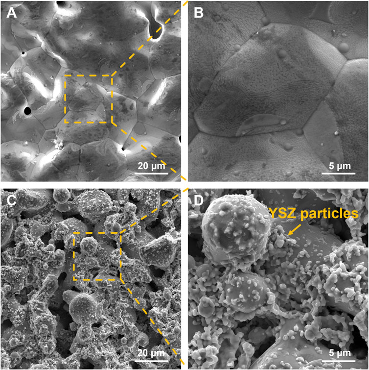
FIGURE 6. SEM images of the sintered SS430L substrate surface sintered at 1400°C for 3 h under purified 5% H2/Ar with 24% starch only (A) and (B) and with 24% starch plus 10 wt.% of YSZ (C) and (D).
Figures 6C,D show SEM images of the surface of a SS430L substrate added with 24 wt.% starch pore-formers and 10 wt.% YSZ. The SS430L particles are well connected, forming a porous framework that can provide high electronic conductivity and strong mechanical strength. The porosity is sufficiently large for the gas transport. Therefore, adding a second phase to inhibit significant grain growth of SS particles and provide gas channels is proved effective.
While adding an oxide second phase seems beneficial to controlling porosity as shown in the aforementioned examples, the remaining question to be answered is how much second phase should be added to the primary phase. From the point of view of electrical conductivity and minimizing the adverse impact on oxidation resistance, it is important to determine the critical amount of second-phase addition. In order to quantitatively evaluate the effects of adding YSZ as a second phase to SS substrate fabrication, a series of tests with 0, 5, 10, 15, and 20 wt.% of YSZ addition are performed. The results are presented in Figure 7.
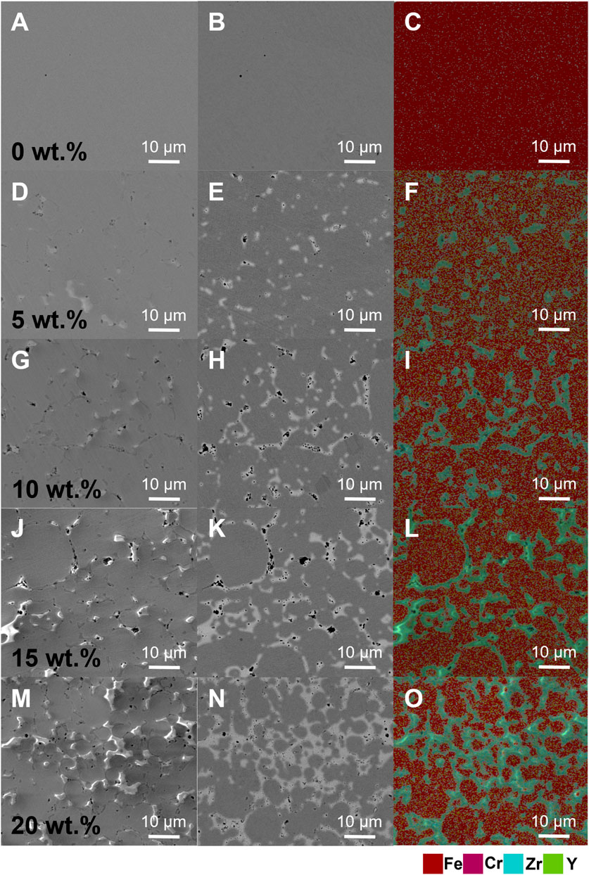
FIGURE 7. Cross sections of SS430L/YSZ samples with varying YSZ contents: SEM images (A, D, G, J, and M); BSE images (B, E, H, K, and N); and the energy dispersion spectrum (C, F, I, L, and O).
Figure 7 shows that for 0 wt.% of YSZ addition, the SS substrate formed a nearly dense metal substrate with large grains, so that the whole frame in Figures 7A–C of different presenting modes shows a uniform phase. Adding 5 wt.% of YSZ led to the formation of the isolated YSZ phase, but the SS grains are still large. When the YSZ content was increased to 10 wt.%, the grain growth of SS grains seemed to be effectively constrained, forming grains of around 10–30 μm wide, as indicated by both the BSE image (Figure 7H) and energy dispersion spectrum (Figure 7I). Furthermore, increasing the YSZ content to 15% and 20% did not yield many changes in grain distribution and network morphology, meaning that the effect of adding YSZ as a second phase reached an optimum value around 10–20 wt.%.
However, since YSZ has a much lower electrical conductivity than SS, the conductivity of the SS430L/YSZ metal support should be reduced as compared to using a single-phase metal or alloy, as proved in Figure 8. On average, the reduction in conductivity with the increasing YSZ content shows a linear correlation for up to 20 wt.% of YSZ addition. The conductivity at all temperatures shows a metallic-type behavior, the slopes are negative, and the absolute value decreases with the increasing YSZ content. The lines are expected to eventually become flat at some point and then should start to show a positive slope in the YSZ dominant region.
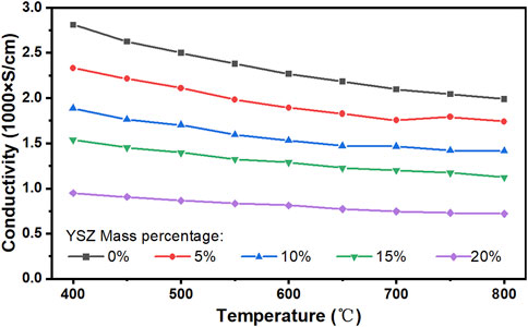
FIGURE 8. Measured electrical conductivity of the SS430L/YSZ metal support (without the addition of pore-formers). The weight percentages of YSZ are based on SS430L.
Mechanical property is another important factor to be considered while adding a second phase. Since YSZ and SS have similar thermal expansion coefficients, we do not expect a very large change in the thermal expansion after adding YSZ, as evidenced in Figure 9, where the thermal expansion behavior of the dense SS430 metal support with 10 wt.% of YSZ only and a porous SS430 metal support with a 10 wt.% of YSZ plus 24 wt.% of starch are compared. The thermal expansion behavior shows a good linearity in the temperature range of 100–800°C under the N2 atmosphere. The measured coefficient of thermal expansion (CTE) of YSZ/SS430L rods with porous structures and dense structures was 11.66 × 10⁻⁶ K−1 and 13.12 × 10⁻⁶ K−1, respectively. The difference in the thermal expansion behavior between the two is mainly due to the different structures. The pores in the material decreased thermal expansion, bringing the CTE closer to that of bare YSZ reported as 10.5 × 10⁻⁶ K−1 by Yasuda and Hishinuma, (2000). The experiment shows that the SS430L/YSZ porous substrate still has a good CTE matching with the YSZ electrolyte. Figure 9 also shows that without the protective gas, both porous and dense samples showed rapid oxidation around 650°C, which is represented by the rapid rise of the CTE curve.
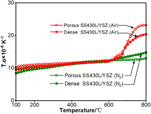
FIGURE 9. Thermal expansion behavior of the SS430L/YSZ porous and dense rods. The dense samples contain 10 wt.% of YSZ only; the porous samples contain 10 wt.% of YSZ plus 24 wt.% of starch. The weight percentages of YSZ and starch are based on SS430L.
3.3 Microstructure and electrochemical performance of MS-SOFC button cells
Figure 10 shows the cross section of an as-sintered MS-SOFC half-cell without cathode application and testing. The YSZ electrolyte layer is dense with nearly no pores. The thickness of the YSZ layer is around 8 μm, which is a suitable thickness for SOFCs with the YSZ electrolyte and is typically not limiting the cell performance (Zhu, Zhang et al., 2015). The anode layer is around 55 μm with relatively low porosity; the estimated porosity of this layer via the image processing software is around 10%. While such low porosity helps densify the electrolyte layer and leads to the high open-circuit voltage (OCV), it may cause relatively large concentration polarization. The SS430L/YSZ substrate is porous with relatively large open pores, which is favorable for gas transport. The estimated porosity in the SS430L/YSZ substrate is around 40%. YSZ grains are randomly distributed in SS430L grains. Overall, the cell structure is desirable for a MS-SOFC, particularly the thin and dense electrolyte layer.
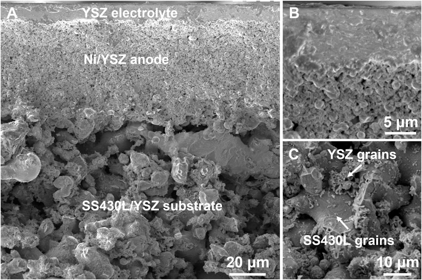
FIGURE 10. SEM images of the following materials: (A) fracture cross section of the MS-SOFC button cell; (B) enlarged image of the electrolyte; and (C) enlarged image of the SS430L/YSZ substrate.
Figure 11A shows the SEM image of the cross section of a tested MS-SOFC button cell with a spray-coated LSCF cathode. Figures 11B,C show the enlarged view of the cathode and surface view of the electrolyte before the application of the cathode, respectively. The SEM image shows that the YSZ electrolyte layer is about 8 μm thick and is tightly bonded to the underneath anode support layer. The electrolyte layer is quite dense, as also supported by the surface view. This is the main reason that we observed high OCV of around 1.1 V at 800°C. The anode layer, even after testing, shows low porosity, which we believe is one of the major limiting factors for the lower-than-expected cell performance as to be discussed further. The LSCF cathode prepared by ultrasonic pyrolytic spraying forms a porous structure. Based on the porosity and thicknesses in both the anode and cathode layer, further optimizations are still needed. Nevertheless, the well-bonded interface and dense electrolyte layer are still encouraging for this type of MS-SOFCs.
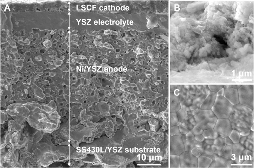
FIGURE 11. SEM images of the following materials: (A) fracture cross section of the MS-SOFC button cell; (B) fracture cross section of the ultrasonic pyrolytic-sprayed LSCF cathode; and (C) surface of the electrolyte.
The cell and cathode performance and stability are presented in Figure 12. The curves in Figures 12A,B show the power generation characteristics and EIS, respectively, of a single button cell using dry hydrogen and ambient air as the fuel and oxidizer, respectively. The maximum power density at 800°C and 750°C is about 180 mW cm-2 and 122 mW cm-2, respectively. The corresponding OCVs are 1.13 V and 1.12 V, respectively. Although the performance is lower than expected, the results indicate that the developed manufacturing process can be successfully applied to the production of button cells. Nevertheless, powder metallurgy co-sintering in the absence of a metal barrier layer inevitably leads to Cr poisoning of the anode due to the diffusion and evaporation of Cr from the steel. The ohmic resistances seem reasonably low, whereas the polarization resistances are relatively large (Figure 12B). Since for our spray-coated cathode, the firing temperature is low and the testing period is relatively short, the diffusion of cathode materials such as Sr onto the electrolyte interface is not expected to play a significant role on the performance. For future cell development, a gadolinium-doped ceria (GDC) diffusion barrier layer will be added on top of YSZ. Figure 12C shows the EIS for an ultrasonic pyrolysis-sprayed LSCF symmetric cell. It can be seen from the diagram that the polarization impedance decreases as the temperature rises, and its polarization resistance is 0.087 Ω cm2 at 800°C. This indicates that the ultrasonic pyrolysis-sprayed LSCF alone at a high temperature has good electrochemical catalytic activity. By comparing Figures 12B,C, it may be concluded that the anode side is predominantly limiting the cell performance as compared with the cathode performance. The relatively low porosity in the anode layer and the lack of a diffusion barrier layer could be the major reasons. Based on the morphology of the anode microstructure and combined impedance data, we believe that future optimization should be conducted on anode porosity and inserting a barrier layer between the anode and the SS support, while the cathode structural optimization and a diffusion barrier layer between the cathode and the electrolyte are also desired. Figure 12D shows the short-term stability test for a similarly prepared cell as that shown in Figure 12A. While the power output is relatively low due to the large polarization resistance, the cell showed stable operation for about 100 h after about 40 h of the initial activation process (the termination of testing was due to an electrical power outage).
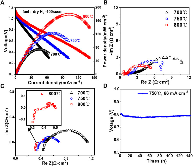
FIGURE 12. (A) MS-SOFC button cell I–V curve; (B) EIS of the MS-SOFC button cell; (C) EIS results of ultrasonic pyrolysis-sprayed LSCF cathodes at different temperatures; and (D) short-term stability test for a cell similarly prepared as in (A).
4 Summary
In this study, SS430L/YSZ metal supports were prepared by powder metallurgy, and MS-SOFC button cells with the SS430L/YSZ|Ni/YSZ|YSZ|LSCF structure were prepared by co-sintering and ultrasonic pyrolytic spraying. This process reduces production costs and simplifies the process of making MS-SOFCs more economical. The experimental results and thermodynamic analysis both suggest and prove that the controlling of trace oxygen levels in the dilute H2/Ar gas mixture is very critical to SS430L substrate sintering. The addition of YSZ to SS430L significantly affects the morphology of the fabricated metal supports. The microstructure of metal supports can be tailored by adjusting the YSZ content in the mixed metal powder. Our results suggested that adding no more than 10 wt.% of YSZ (SS430L:YSZ = 9:1) as a second phase substantially minimized the over-sintering of the SS support, leading to a more porous metallic-type substrate, while the electrical conductivity and thermal expansion were not much affected. The fabricated MS-SOFCs exhibit 180 mW cm-2 at 800°C with an OCV of 1.13 V, using dry hydrogen as the fuel and ambient air as the oxidant. A cell similarly tested at 750°C under a current density of 66 mA cm-2 and voltage of ∼0.8 V showed a relatively stable operation for a period of 140 h. Both the high OCV and stable operation support that the powder metallurgy and atmosphere-controlled co-sintering process is a promising method for the preparation of MS-SOFCs.
Data availability statement
The raw data supporting the conclusion of this article will be made available by the authors, without undue reservation.
Author contributions
SF: experimental investigations, data analysis, and writing and editing the manuscript; JZ and KX: experimental investigations; JY: discussion and analysis; LZ: supervision, conceptualization, data analysis, and writing and editing the draft. All authors have read and agreed to the published version of the manuscript.
Funding
The authors would like to acknowledge funding support from the Ningbo Municipal Government and Chinese Academy of Science.
Acknowledgments
The authors acknowledge support from the solid oxide fuel cell team at the Ningbo Institute of Materials Technology and Engineering, Chinese Academy of Sciences. They also appreciate helpful discussions from the R&D department of NBTM New Materials Group Co., Ltd. in Ningbo City, China.
Conflict of interest
The authors declare that the research was conducted in the absence of any commercial or financial relationships that could be construed as a potential conflict of interest.
Publisher’s note
All claims expressed in this article are solely those of the authors and do not necessarily represent those of their affiliated organizations, or those of the publisher, the editors, and the reviewers. Any product that may be evaluated in this article, or claim that may be made by its manufacturer, is not guaranteed or endorsed by the publisher.
References
Anderson, M. P., Grest, G. S., Doherty, R. D., Li, K., and Srolovitz, D. J. (1989). Inhibition of grain growth by second phase particles: Three dimensional Monte Carlo computer simulations. Scr. Metall. 23 (5), 753–758.
Blennow, P., Hjelm, J., Klemensø, T., Ramousse, S., Kromp, A., Leonide, A., et al. (2011). Manufacturing and characterization of metal-supported solid oxide fuel cells. J. Power Sources 1 96.
Chang, K., Feng, W., and Chen, L.-Q. (2009). Effect of second-phase particle morphology on grain growth kinetics. Acta Mater. 57 (17), 5229–5236.
Clark, D., Malerød-Fjeld, H., Budd, M., Yuste-Tirados, I., Beeaff, D., Aamodt, S., et al. (2022). Single-step hydrogen production from NH3, CH4, and biogas in stacked proton ceramic reactors. Science 376 (6591), 390–393.
Dogdibegovic, E., Wang, R., Lau, G. Y., and Tucker, M. C. (2019). High performance metal-supported solid oxide fuel cells with infiltrated electrodes. J. Power Sources 410-411, 91–98.
Franco, T., Haydn, M., Weber, A., Schafbauer, W., Blum, L., Packbier, U., et al. (2013). The status of metal-supported SOFC development and industrialization at plansee. ECS Trans. 57 (1), 471.
Hauch, A., Küngas, R., Blennow, P., Hansen, A. B., Hansen, J. B., Mathiesen, B. V., et al. (2020). Recent advances in solid oxide cell technology for electrolysis. Recent Adv. solid oxide Cell Technol. electrolysis 370.
Haydn, M., Ortner, K., Franco, T., Uhlenbruck, S., Menzler, N. H., Stöver, D., et al. (2014). Multi-layer thin-film electrolytes for metal supported solid oxide fuel cells. J. Power Sources 256, 52–60.
Krishnan, V. V. (2017). Recent developments in metal-supported solid oxide fuel cells. Energy Environ. 6 (5), e246.
McKenna, B. J., Christiansen, N., Schauperl, R., Prenninger, P., Nielsen, J., Blennow, P., et al. (2013). Advances in metal supported cells in the METSOFC EU consortium. Fuel cells 13 (4), 592–597.
Nielsen, J., Persson, Å. H., Muhl, T. T., and Brodersen, K. (2018). Towards high power density metal supported solid oxide fuel cell for mobile applications. J. Electrochem. Soc. 165 (2), F90.
Oishi, N., Rudkin, R., Steele, B. C. H., Atkinson, A., Brandon, N. P., and Kilner, J. A. (2002). “Stainless steel supported thick film IT-SOFCS for operation at 500–600°C—fabrication of ceria film on stainless steel substrate by EPD,” in Electrochemical Society Proceedings, PV, 2002–21, 230–237.
Rüttinger, M., Mücke, R., Franco, T., Büchler, O., Menzler, N. H., and Venskutonis, A. (2011). Metal-supported cells with comparable performance to anode-supported cells in short-term stack environment. ECS Trans. 35 (1), 259.
Steele, B. C. H., Atkinson, A., Kilner, J. A., Brandon, N. P., and Rudkin, R. A. (2004). Fuel cells, US patent, patent No. US006794075B2. London, UK: Ceres Power Limited.
Tucker, M. C. (2017). Development of high power density metal-supported solid oxide fuel cells. Energy Technol. 5 (12), 2175–2181.
Tucker, M. C. (2010). Progress in metal-supported solid oxide fuel cells: A review. J. Power Sources 195 (15), 4570–4582.
Udomsilp, D., Rechberger, J., Neubauer, R., Bischof, C., Thaler, F., Schafbauer, W., et al. (2020). Metal-supported solid oxide fuel cells with exceptionally high power density for range extender systems. Cell Rep. Phys. Sci. 1 (6), 100072.
Welander, M. M., Hu, B., and Tucker, M. C. (2022). Metal-supported solid oxide fuel cells operating with reformed natural gas and sulfur. Int. J. Hydrogen Energy 47 (21), 11261–11269.
Xu, Q., Guo, Z., Xia, L., He, Q., Li, Z., Temitope Bello, I., et al. (2022). A comprehensive review of solid oxide fuel cells operating on various promising alternative fuels. Energy Convers. Manag. 253, 115175.
Yasuda, I., and Hishinuma, M. (2000). Lattice expansion of acceptor-doped lanthanum chromites under high-temperature reducin'g atmospheres. Electrochemistry 68 (6), 526–530.
Zarabi Golkhatmi, S., Asghar, M. I., and Lund, P. D. (2022). A review on solid oxide fuel cell durability: Latest progress, mechanisms, and study tools. Renew. Sustain. Energy Rev. 161, 112339.
Zhang, L., Zhu, L., and Virkar, A. V. (2016). Nanostructured cathodes for solid oxide fuel cells by a solution spray-coating process. J. Electrochem. Soc. 163 (13), F1358–F1365.
Keywords: SOFC, metal-supported SOFC, second-phase sintering, 430L stainless steel sintering, thermal spray coating
Citation: Fu S, Zhang J, Xu K, Yang J and Zhu L (2023) Fabrication, property and performance evaluation of Stainless Steel 430L as porous supports for metal supported solid oxide fuel cells. Front. Energy Res. 11:1127900. doi: 10.3389/fenrg.2023.1127900
Received: 20 December 2022; Accepted: 19 January 2023;
Published: 08 February 2023.
Edited by:
David Marrero-López, University of Malaga, SpainReviewed by:
Lucía Dos Santos-Gómez, University of Malaga, SpainSoumendra Basu, Boston University, United States
Copyright © 2023 Fu, Zhang, Xu, Yang and Zhu. This is an open-access article distributed under the terms of the Creative Commons Attribution License (CC BY). The use, distribution or reproduction in other forums is permitted, provided the original author(s) and the copyright owner(s) are credited and that the original publication in this journal is cited, in accordance with accepted academic practice. No use, distribution or reproduction is permitted which does not comply with these terms.
*Correspondence: Liangzhu Zhu, emh1bGlhbmd6aHVAbmltdGUuYWMuY24=