 Khaled Alkhaledi1
 Khalid Mehmood Cheema
 Z. M. Salem Elbarbary
 Ahmed M. El-Sherbeeny
95% of researchers rate our articles as excellent or good
Learn more about the work of our research integrity team to safeguard the quality of each article we publish.
Find out more
ORIGINAL RESEARCH article
Front. Energy Res. , 16 May 2023
Sec. Smart Grids
Volume 11 - 2023 | https://doi.org/10.3389/fenrg.2023.1125461
This article is part of the Research Topic Operation and Control in Smart Electric Power Systems: Methods and Applications View all 5 articles
The distributed power generation is increasing rapidly, and its integration into the power system is a critical issue for the existing power network. Therefore, a three-level converter is developed to access and control the medium voltage DC generated from a photovoltaic system in a smart grid. A conventional three-level neutral point clamped circuit is incorporated into the conventional inverter. The conventional inverter is a pulse width modulation-based inverter that achieves zero switching currents and supplies power to the load. This technique suppresses the switching power loss up to a large extent. Additionally, switches conduct half of the input voltage; therefore, the output voltage is significantly similar to the voltage of the output filter. Moreover, in the proposed converter, the stress of voltage on diodes is minimal, which increases the input range of voltage in smart grids. The overall efficiency of converter is around 97.9% and voltage gain is around 42. In addition to these, a detailed design description and analysis are carried out in this paper. In the end, a prototype is developed for experimental analysis to validate the operating principle and characteristics of the proposed converter.
The stocks of fossil fuels have been depleted significantly and are unable to meet the needs of the sustainable development of human society. The power generation from fossil fuels causes pollution, and the extraction of these fuels damages the earth’s environment (Cheema, 2020). On the other hand, renewable energy resources based on distributed generation are widely distributed, flexible, and pollution-free. Power generation from a photovoltaic system is a form of distributed power generation, and it is pretty suitable for sustainable development of a smart grid system (Cheema and Mehmood, 2020). In recent years, a large number of photovoltaic farms have been integrated into conventional power systems (Hassan et al., 2020; Cheema et al., 2021a).
The DGs consisting of photovoltaic systems are electronically interfaced with a power system or grid and demonstrate different characteristics than conventional power generating units (Cheema et al., 2021b). In electronically inter-faced DGs, the power generated at the primary side of DGs is supplied to the power system either as DC or AC (Hu and Liu, 2018). The DC converters are widely used to supply and control power to the grid with different configurations (Yao and Lu, 2020). However, the conventional converters possess the characteristic of switching losses (Quan and Li, 2018). In order to minimize the switching losses, the resonance method is applied by implementing zero-volt switching (ZVS) and zero current switchings (ZCS) technique which achieve the zero voltage and current (Yin et al., 2016; Chou et al., 2019). Additionally, these converters possess two different types of filter techniques which are series and parallel LC resonant filters (Nouri et al., 2021).
Moreover, the DGs consisting of photovoltaic systems supply DC power, and it is quite easy to couple different DC sources via a medium voltage DC collection system (Zheng et al., 2021). Additionally, these developed system does not suffer from frequency, power angle, and active/reactive power instability issues. Due to these advantages, it is considered that the medium voltage DC collection system is the future of the power system (Bagherian et al., 2021). However, the terminal voltage of a photovoltaic panel is quite low; therefore, the high gain DC-DC converters are incorporated to transfer the generated power to the medium voltage DC collection system (Mohseni et al., 2021).
A significant number of researchers developed different types of DC-DC converter (Hasanpour et al., 2020; Upadhyay and Kumar, 2020; Alagu et al., 2021). For example, in (Srinivasan and Kwasinski, 2020), researchers presented a DC-DC converter based on switched capacitor method. The authors concluded that the switched capacitor method-based converters possess low output capacitance, and their component power consumption is on the lower side too. On the other side, in (Wang et al., 2020), the authors introduced the resonant switched capacitor-based converter. The switching losses are quite low in this type of converter due to the soft switching approach. However, besides such advantages, these converters experience significantly high voltage stress due to their no isolated nature. To overcome this issue, transformers are incorporated into converters. Transformers provide the isolation characteristic and high gain even in low voltage applications. Considering the isolated characteristic, various type of modified converters is developed (Baek and Park, 2012; Faraji et al., 2019; de Souza et al., 2021). Moreover, in (Raziq et al., 2023), authors proposed the zero-sequence control for balance power production during unstable input parameters. The zero-sequence voltage is fed to each phase of the converter for accurate balance power in all phases. Consequently, in (Yadav and Singh, 2023), researchers proposed a solar multilevel converter with closed-loop control to integrate solar PV arrays with medium voltage grid. The multilevel converter produces higher number of levels in the output voltage with less usage of semiconductor switches. The key focus of their research is to minimize the number of switches which lessens the sum of driver circuits for a power converter. Furthermore, in (Mishra et al., 2023), authors introduce the fifteen-level packed U cell converter for single-phase grid connected applications. The detailed analysis depicts that the total harmonic distortion of grid current is under 5%. The converter voltage total harmonic distortion is 7.8%, which is quite low at 500 Hz switching frequency. A less complex, active reactive power control with a balanced floating capacitor voltage is implemented. The balancing of capacitor voltages is achieved for both the capacitors under the dynamic solar photovoltaic environment. The unity power factor operation is achieved with a compact and efficient fifteen-level PUC converter-based grid-tied system. In addition to these, in (Alotaibi et al., 2023) the scientist presents a new three-phase modular inverter which is based on a novel dual-isolated SEPIC/CUK converter for large-scale PV power plants. The proposed three-phase modular inverter is produced from series DISC submodules to reduce the size and improve the performance of the energy conversion system. Employing high-frequency transformers into the submodules can provide the required galvanic isolation and voltage boosting in addition to reducing the size compared with line-frequency step-up transformers. The chosen DISC converter reduces the required filtering capacitances, resulting in improved lifetime, scalability, and resilience of the inverter.
The phase shift full-bridge converter is postposed in (Ye et al., 2018; Haneda and Akagi, 2020). The advantage of the phase shift full bridge converter is that it can attain zero voltage switching. However, it has to compromise on the switching loss and high circulating current. To overcome these issues, various researchers incorporated modifications into the fundamental structure of converters, such as the addition of active/passive elements. Additionally, the state-of-the-art review for multilevel inverter are presented in (Bughneda et al., 2021a; Alatai et al., 2021; Bughneda et al., 2022) and briefly outlined the aspects of multilevel inverters to highlight the need to produce new inverters or modified combinations of inverters for grid-connected and PV systems. A modified five level inverter in presented in (Bughneda et al., 2021b) and the proposed modified five level cascaded H-bridge inverter uses the fewer switches in comparison to conventional cascaded H-bridge inverter. Therefore, its efficiency and cost are better which makes it suitable for industrial uses. Similar to that, five level cascaded H-bridge LLC resonant converter for battery charger is presented in (Alatai et al., 2022). This converter is designed to obtain high power density, high efficiency, and less magnetic components to ensure the reduction on factors of size and cost. However, the efficacy of this converter is around 96.9%.
Consequently, in (Dworakowski et al., 2020), the authors presented the single active bridge converter and it is concluded that the interleaving technique can reduce the overall output current, but this technique has a severe disadvantage of high turnoff switching current. This high turnoff switching current destroys the efficiency of the converter significantly. In order to develop and maintain a highly efficient medium voltage DC collection system, a new technique is proposed in this research paper, which is significantly better with high efficiency. The key points of this research and inverter are as follows:
1. It consists of a dual transformer for isolation characteristics in a three-level zero current switching DC converter that consists of a neutral point clamped circuit.
2. A simple pulse width modulator is used to achieve the voltage and power regulation of the proposed converter to minimize the complexity.
3. The implementation of a simple pulse width modulator gives two advantages; 1) the circuit complexity is significantly reduced; 2) the switching pattern of converts switches can be easily adjusted.
4. Consequently, by incorporating the elements mentioned earlier, the proposed converter attains zero-current switching under the minimum to maximum load conditions.
5. Furthermore, this technique minimizes the converter switching losses.
Besides this, the remainder of this paper is organized as follows; Section 2 describes the proposed converter circuit and operational sequence. Section 3 explains the theoretical analysis, and the selection of proposed converter parameters is discussed in Section 4. Section 5 presented the simulation results followed by the experimental results in Section 6. Section 7 concludes the current study.
The schematic diagram of the proposed converter is depicted in Figure 1. The schematic diagram can be split into three divisions.
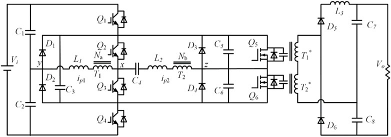
FIGURE 1. Detailed design of proposed converter.
The first division consists of switches Q1-Q4, resonant inductances L1-L2, clamping diodes D1-D2, Capacitor C1- C2, and transformer T1. Consequently, the second division consists of switches Q5-Q6, diodes D3-D4, capacitor C3-C4 inductor L1-L2 and second transformer T2. The third division consists of capacitor C7-C8 and diode D5-D6. The detailed design development method is discussed in the next section.
The converter waveforms are depicted in Figure 2. The converter switch set Q1-Q2 and Q3-Q4 switch at the same time and keeping the reasonable delay. Moreover, to analyze the system, the following assumptions are made.
a. All the active and passive devices are ideal, including semiconductor devices.
b. The capacitors rating is significantly large in all divisions of the converter.
c. Transformers of the converter have negligible leakage inductance.
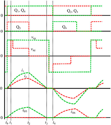
FIGURE 2. Switching pattern of proposed converter.
The switching sequence of the half-cycle of the converter is depicted in Figure 3.
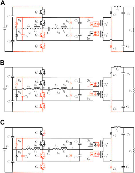
FIGURE 3. Equivalent circuits of different operational modes of proposed converter (A) [t0, t1] (B) [t1, t2] and (C) [t2, t3].
I. [t0]: The switching cycle starts from t0. At t0, the switch Q3-Q4 is turned off and depicted in dotted red line; whereas, the turn-on section is depicted in solid line.
II. Mode 1 [t0, t1]: In this mode, the current i1 of T1 flows through the transformer windings Q1, Q2, L1, T1, and C1, as can be seen in Figure 3A. Similarly, the i2 of T2 flows through the transformer windings of Q1, Q2, T2, Q5, C4, D2, L2 and C1. In this mode, only L1 is the resonant inductor.
III. Mode 2 [t1, t2]: In this mode, i2 flows from switch Q6, whereas i1 continues to flows from its previous path, as depicted in Figure 3B. Moreover, L1 and L2 resonate with C3.
IV. Mode 3 [t2, t3]: In this mode, Q5 closes at time t2. Moreover, i2 charges the C4 to achieve the zero-voltage switching. The C4 charges very quickly, and the current path is depicted in Figure 3C.
V. t4: The half-switching cycle ends at t4. At the end of the half-cycle, Q1 and Q2 became turned off with zero current switching, whereas Q3, Q4, and Q6 become turned on.
The literature analysis shows that researchers consider different power and switching frequencies with a large input and output voltage range. Therefore, the resonant angular frequency and resonant impedance of the equivalent circuit can be expressed as:
Furthermore, the [t1, t2] and [t2, t3] can be expressed as:
The steady-state route of the converter is shown in Figure 4. The circular line Ya→Wa depicts the [t0, t1] sequence. In contrast, the t→Yb depicts the [t1, t2] sequence. Similarly, the Yb →Wb represents the t2, t3] sequence during the second half cycle.
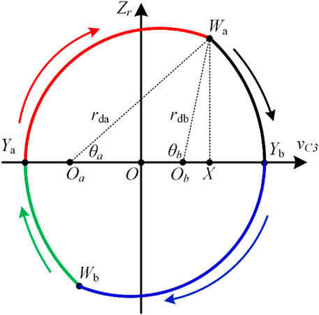
FIGURE 4. Steady-state trajectory of proposed converter.
Considering Figure 4, the radius of red color curve rda and radius of black curve rdb can be stated as:
Furthermore, the angle θa and θb can be stated as:
Additionally, in this paper, the following parameters are considered for the proposed converter for theoretical analysis.
Rated power = 1000 W.
Input voltage = 300 and 600 V.
Transformer 1 turn ratio = 0.21.
Transformer 2 turn ratio = 0.29.
Switching frequency = 10, 000 Hz.
The proposed converter is incorporated with two transformers. Therefore, selecting the suitable turn ratio for both transformers is critical to transfer maximum power without losses. In order to select the suitable turn ratio, it is necessary to develop a hypothesis that the converter is ideal and convert power completely without losses. Therefore, the overall power of the first half cycle can be expressed as:
Similarly, the transmission power of T1 is
By Eq. 5 and simplified terms of Eq. 6, we can write
Furthermore, the transmission power of the second transformer can be written as:
Now incorporating (Eqs 7, 8) together, the resultant expression can be stated as:
The relationship of total power, power of transformer 1 and transformer 2 is depicted in Figure 5. According to Figure 5, transformer 1 turn ratio and Pa/P are directly proportional to each other; whereas, transformer 1 turn ratio and Pb/Pb is inversely proportional.
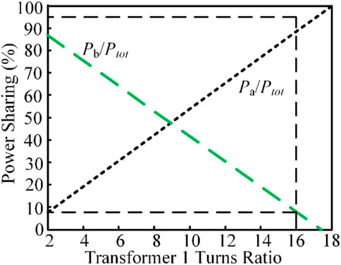
FIGURE 5. Relationship between transformer 1 turn ratio and power sharing.
In order to select the optimal performing resonant capacitor, it is assumed that the converter and its component are ideal without losses. Therefore, during the first half cycle, the output power of the converter can be stated as:
If we substitute (6) into (10), the resultant expression can be stated as:
According to the state analysis in mode 4, we should know that VL1, VC4, and VL2 should be satisfied.
The same assumption of an ideal converter is considered while selecting the optimal performing resonant inductors. In the proposed converter, two resonant inductors are incorporated along with a single capacitor. For ease of analysis, the value of resonant inductors is chosen to be the same in the entire theoretical and experimental analysis. Therefore, for the first half cycle, the expression for resonant inductor can be stated as:
The value for optimal performing should be greater, as observed from Eq. 12.
The frequency response of the LC resonant circuit for various values of QF is illustrated in Figure 6. It can be observed that the parallel-loaded resonant circuit shows high-voltage gain for higher values of QF. Moreover, considering the certain operating frequency, the voltage gain is around 42.
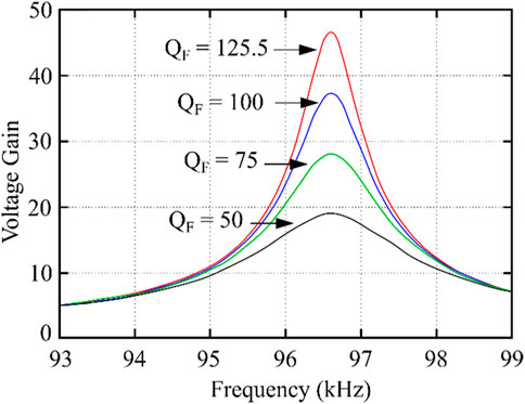
FIGURE 6. Voltage gain and frequency response of resonant circuit.
For an optimal performance converter, it is necessary to be selective and design the optimal transformer turn ratio and resonant capacitor. Considering the given parameters in Section 3 and formulas, we get Figure 7, which depicts that the increment in transformer turn ratio is inversely proportional to turn off current in the converter. Therefore, it is concluded that the lower value of the transformer turn ratio decreases the switching losses. Similarly, Figure 8 depicts the relationship among transformer turn ratio, resonant capacitor, and peak current of switches. It can be observed from Figure 8 that the peak current of switches decreases smoothly with increasing the value of the resonant capacitor. However, the peak current of switches decreases rapidly by increasing the value of the transformer turn ratio. Therefore, to reduce the peak current to facilitate switching selection, the lower transformer turn ratio must be selected.
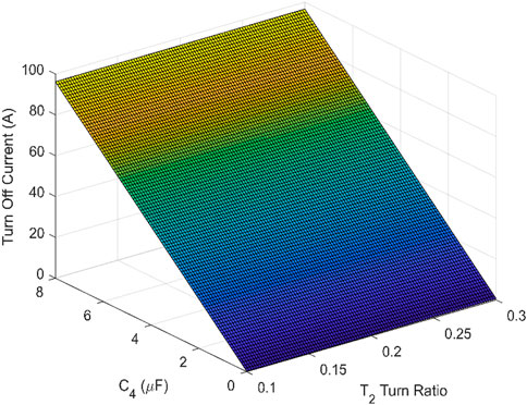
FIGURE 7. Relative slop among turn off current, transformer 2 turn ratio and capacitor C4.
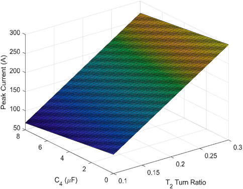
FIGURE 8. Relative slop among peak current, transformer 2 turn ratio and capacitor C4.
The change in the difference of voltage of resonant capacitor and inductors is dependent on the values of transformer turn ratio and resonant capacitor. Therefore, Figures 9A, B depict the change in the difference of voltage of resonant capacitor and inductors, respectively. In Figure 9A, it can be observed that the value of change in the difference of voltage of resonant capacitor decreases when the value of transformer turns ratio or resonant capacitance decreases. Subsequently, the change in the difference of voltage of resonant inductors is depicted in Figure 9B. It canx be observed in Figure 9B that when the value of the transformer turns ratio decreases, the change in the difference of voltage of resonant inductors decreases. Whereas, when the value of resonant inductors decreases, the change in the difference of voltage of resonant inductors increases.
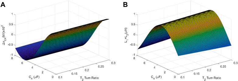
FIGURE 9. Relative slop among (A) change in voltage of capacitor C4, transformer 2 turn ratio and capacitor C4 (B) resonant inductors, transformer 2 turn ratio and capacitor C4.
The theoretical analysis is performed in the previous section, and it is observed that the proposed converter design is efficient. To strengthen the theoretical analysis, simulations are performed by using the equations and parameters defined in the previous section. The input and the output of the simulation is shown in Figures 10, 11. The resonant circuit input waveforms voltage, and the input current are plotted as shown in Figure 10. It can be observed that the converter operates above the resonant frequency of resonant circuit; the current iin lags the vAB.
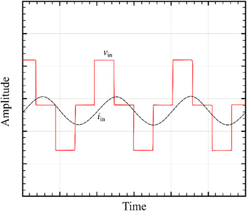
FIGURE 10. Input Voltage and current waveform.
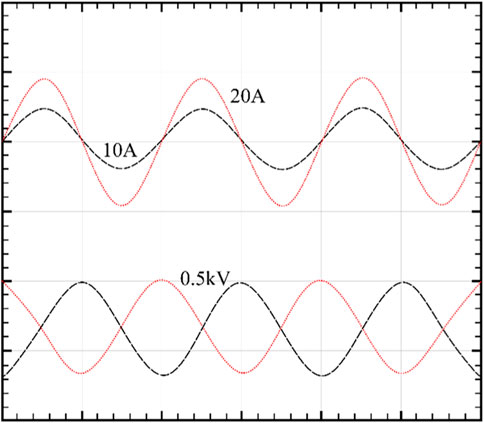
FIGURE 11. Simulation result of proposed converter indicating current and voltage.
In contrast, it can be observed in Figure 11 that when the turn ratio is increased, the peak current 1 and Peak current 2 increase, too, along with the turnoff current. In contrast, change in voltage decreases significantly. It can be seen in Figure 11 that the value of peak current 1 is 20 A and the value of peak current 2 is 10 A. Whereas the theoretical values for peak current 1 and 2 is 20.15 and 10.18, respectively. Consequently, simulation results endorse the theoretical analysis of the proposed system.
In order to validate the performance of the proposed converter, a three-level 1000 W prototype circuit operating at 10,000 Hz is developed. The proposed and developed circuit tested on low and medium input voltage in two different cases. For Case I, the input voltage set at 300 v and for Case II, the input voltage set at 600 V. The parameters and components specification of the prototype are shown in Table 1.
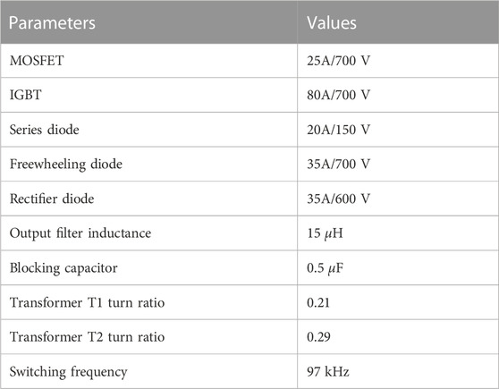
TABLE 1. Main platform parameters.
The resultant output of the experiment is depicted in Figure 12. It can be observed that Figure 12 is a three-level converter because VC4 is representing the combined voltage of transformer 1 and transformer 2.
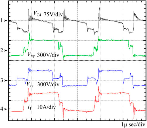
FIGURE 12. Output of VC4, VXY, VXZ and i.
When a small load is applied to the converter while the input voltage is at lower end, it works in two-level modes, whereas for medium to heavy load and with medium voltage, converter operates in three-level mode as shown in Figure 13.
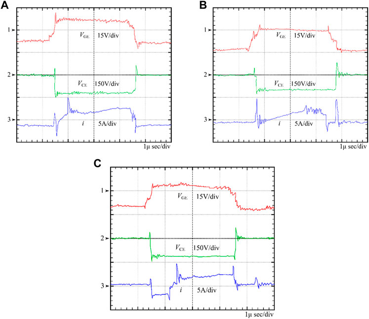
FIGURE 13. Case 1 output of VGE, VCE, and i for (A) Q1 (B) Q2 and (C) Q5.
Figure 13A shows the output result when a load is applied with 300v input voltage. The switch Q1 achieves the zero-voltage switching. Similarly, it can be observed in Figure 13B, the Q2 achieve zero current switching. Moreover, Figure 13C depicts that peak current 2 reaches zero prior to the turning off of Q5, and in this way, Q5 achieves the zero-current turnoff. Additionally, an abrupt fluctuation in current can be seen, which is the result of Q5 output capacitance. Thus, the results from the experiment setup support the theoretical analysis of the previous section.
Subsequently, the input of converter is shifted from low end to medium end at the resultant waveforms of VCE, VCE, and current of Q1 are shown in Figure 14. It can be observed that the input voltage is 300V, and the zero-voltage switching is achieved when the antiparallel diode is still on. Moreover, it has no follow-up or tails current from other switches due to efficient zero current switching. Similarly, Figures 14B, C show the values of VGE, VCE, and current of Q2 and Q5, respectively. It can be observed that the value of peak voltage of Q2 and Q5 is around a quarter of the input voltage. Consequently, the voltage remains zero prior to the conduction of Q5; therefore, Q5 realizes the zero voltage and zero current switching.
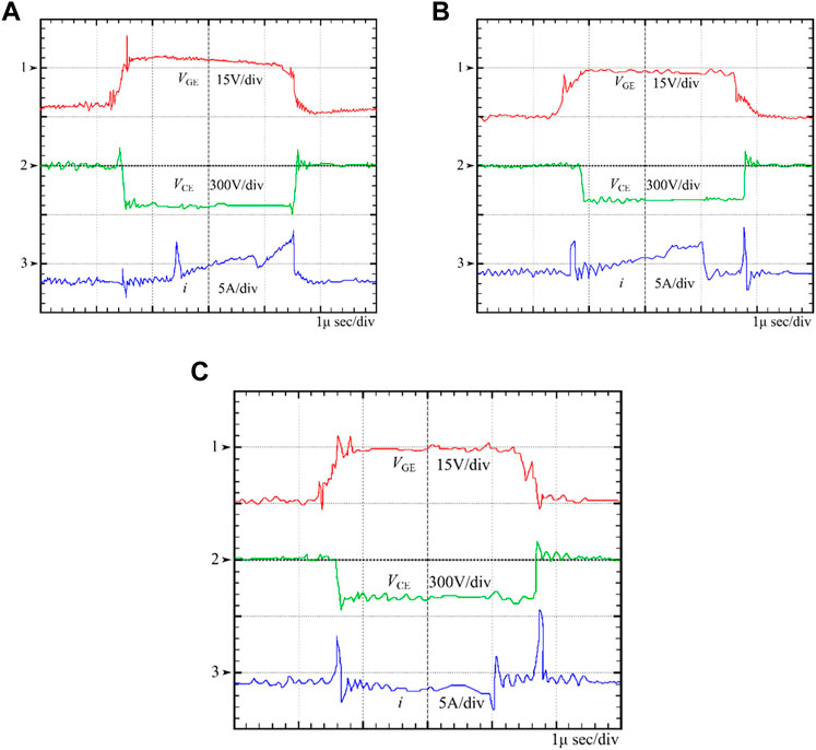
FIGURE 14. Case 2 output of VGE, VCE, and i for (A) Q1 (B) Q2 and (C) Q5.
Figure 15 represents the voltage across the tank as a function of the input voltage of inverter. The simulation results illustrates that the tank voltage fluctuates nearly linearly with the input of the inverter. Though, experimental and prototype result is slightly different because the corresponding series resistance of L3 is not involved in the simulation model, which results in a voltage drop in the output values. Moreover, for the experimental results, the increase in the tank voltage is not linear because of the fact that saturation occurs in the tank.
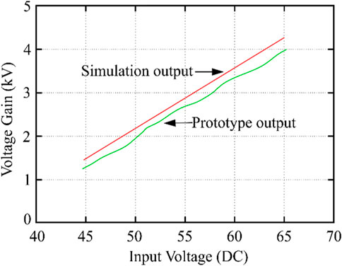
FIGURE 15. Frequency and voltage gain response of LC resonant circuit.
Moreover, Figure 16 depicts the breakdown of power losses in the proposed converter. It can be observed that IGBTs and output diodes are the major sources of power losses for both cases. The proposed converter is designed for medium voltage; therefore, the power losses for Case I are higher in comparison to Case II power losses.
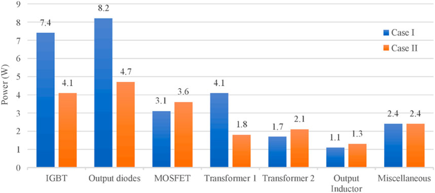
FIGURE 16. Power loss of proposed converter.
Lastly, Figure 17 represents the proposed converters prototype efficiency curve. The green curve depicts the efficiency for Case I and it can be observed that at low voltage and low load condition efficiency of converter is around 97%. In contrast, for Case II, medium voltage and load the converter efficiency is around 98%. This curve depicts that the proposed converter works effectively on medium input voltage.
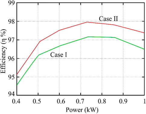
FIGURE 17. Efficiency of proposed converter.
In this paper, a converter is proposed and its design and operating principle is explained in detail. The proposed converter utilizes full-bridge converters in a special way to reduce the power losses and the output filter inductance. The proposed converter is expected to be highly beneficial for a wide power range application. Moreover, the proposed converter consists of a dual transformer and has the advantage of zero current switching and zero voltage switching such as wide range of power application and wide range of input voltage. The voltage and power regulation are achieved by a simple pulse width modulator to avoid the complexity and switching pattern of semiconductor switches can be adjust without any complication. The lower number of devices and simple circuit minimizes the converter switching losses. Additionally, the output filter inductance and the voltage stress on rectifier diodes are reduced. At end, to verify the effectiveness of the converter a prototype is built and tested and it is observed that the converter is around 97.9% efficient. The zero current and zero voltage switching overcomes the huge spikes of current and voltage of conventional converter and provides a technically viable soft-switching. Finally, the experimental results verify the performance of the proposed converter.
The original contributions presented in the study are included in the article/Supplementary Material, further inquiries can be directed to the corresponding author.
Conceptualization, KA and ZE; methodology, KA, ZE, and KC; software, KA, KC, and ZE; validation, KC, W-HP, and AE-S; formal analysis, KA and KC; investigation, ZE. and W-HP; resources, W-HP; data curation, AE-S; writing—original draft preparation, KA, KC, and ZE; writing—review and editing, W-HP and AE-S; visualization, AE-S; supervision, KA; project administration, W-HP; funding acquisition, KA and AE-S. All authors contributed to the article and approved the submitted version.
The authors extend their appreciation to the Deanship of Scientific Research at King Saud University for funding this work through research group number (RG-1438-054).
The authors declare that the research was conducted in the absence of any commercial or financial relationships that could be construed as a potential conflict of interest.
All claims expressed in this article are solely those of the authors and do not necessarily represent those of their affiliated organizations, or those of the publisher, the editors and the reviewers. Any product that may be evaluated in this article, or claim that may be made by its manufacturer, is not guaranteed or endorsed by the publisher.
Alagu, M., Ponnusamy, P., Pandarinathan, S., and Ali, J. S. M. (2021). Performance improvement of solar PV power conversion system through low duty cycle DC-DC converter. Int. J. Circuit Theory Appl. 49, 267–282. doi:10.1002/cta.2918
Alatai, S., Salem, M., Alhamrouni, I., Ishak, D., Bughneda, A., and Kamarol, M. (2022). Design methodology and analysis of five-level LLC resonant converter for battery chargers. Sustainability 14, 8255. doi:10.3390/su14148255
Alatai, S., Salem, M., Ishak, D., Das, H. S., Alhuyi Nazari, M., Bughneda, A., et al. (2021). A review on state-of-the-art power converters: Bidirectional, resonant, multilevel converters and their derivatives. Appl. Sci. 11, 10172. doi:10.3390/app112110172
Alotaibi, S., Darwish, A., and Williams, B. W. (2023). Three-phase inverter based on isolated SEPIC/CUK converters for large-scale PV applications. Int. J. Electr. Power and Energy Syst. 146, 108723. doi:10.1016/j.ijepes.2022.108723
Baek, J., and Park, M. (2012). Fuzzy bilinear state feedback control design based on TS fuzzy bilinear model for DC–DC converters. Int. J. Electr. Power and Energy Syst. 42, 710–720. doi:10.1016/j.ijepes.2012.04.008
Bagherian, A., Nouri, T., Shaneh, M., and Radmehr, M. (2021). An interleaved ZVS ultra-large gain converter for sustainable energy systems applications. IET Power Electron. 14 (9), 1606–1621. doi:10.1049/pel2.12136
Bughneda, A., Salem, M., Alhuyi Nazari, M., Ishak, D., Kamarol, M., and Alatai, S. (2022). Resonant power converters for renewable energy applications: A comprehensive review. Front. Energy Res. 10, 185. doi:10.3389/fenrg.2022.846067
Bughneda, A., Salem, M., Ishak, D., Alatai, S., Kamarol, M., and Hamad, K. B. (2021). “Modified five-level inverter for PV energy system with reduced switch Count,” in 2021 IEEE Industrial Electronics and Applications Conference (IEACon), Penang, Malaysia, 22-23 November 2021, 103–107.
Bughneda, A., Salem, M., Richelli, A., Ishak, D., and Alatai, S. (2021). Review of multilevel inverters for PV energy system applications. Energies 14, 1585. doi:10.3390/en14061585
Cheema, K. M. (2020). A comprehensive review of virtual synchronous generator. Int. J. Electr. Power and Energy Syst. 120, 106006. doi:10.1016/j.ijepes.2020.106006
Cheema, K. M., Mahmood, R. S., Tahir, M. F., Mehmood, K., and Javed, M. Y. (2021). “Modified control of virtual synchronous generator for microgrid stability improvement,” in 2021 International Bhurban Conference on Applied Sciences and Technologies (IBCAST), Islamabad, Pakistan, 12-16 January 2021, 673–677.
Cheema, K. M., and Mehmood, K. (2020). Improved virtual synchronous generator control to analyse and enhance the transient stability of microgrid. IET Renew. Power Gener. 14 (5), 495–505. doi:10.1049/iet-rpg.2019.0855
Cheema, K. M., Milyani, A. H., El-Sherbeeny, A. M., and El-Meligy, M. A. (2021). Modification in active power-frequency loop of virtual synchronous generator to improve the transient stability. Int. J. Electr. Power and Energy Syst. 128, 106668–106679. doi:10.1016/j.ijepes.2020.106668
Chou, D., Lei, Y., and Pilawa-Podgurski, R. C. (2019). A zero-voltage switching, physically flexible multilevel GaN DC–DC converter. IEEE Trans. Power Electron. 35, 1064–1073. doi:10.1109/tpel.2019.2914213
de Souza, A. F., Tofoli, F. L., and Ribeiro, E. R. (2021). Switched capacitor DC-DC converters: A survey on the main topologies, design characteristics, and applications. Energies 14, 2231–2245. doi:10.3390/en14082231
Dworakowski, P., Wilk, A., Michna, M., Fouineau, A., and Guillet, M. (2020). Lagrangian model of an isolated dc-dc converter with a 3-phase medium frequency transformer accounting magnetic cross saturation. IEEE Trans. Power Deliv. 36, 880–889. doi:10.1109/tpwrd.2020.2995879
Faraji, R., Adib, E., and Farzanehfard, H. (2019). Soft-switched non-isolated high step-up multi-port DC-DC converter for hybrid energy system with minimum number of switches. Int. J. Electr. Power and Energy Syst. 106, 511–519. doi:10.1016/j.ijepes.2018.10.038
Haneda, R., and Akagi, H. (2020). Design and performance of the 850-V 100-kW 16-kHz bidirectional isolated DC–DC converter using SiCMOSFET/SBD H-bridge modules. IEEE Trans. Power Electron. 35, 10013–10025. doi:10.1109/tpel.2020.2975256
Hasanpour, S., Siwakoti, Y. P., Mostaan, A., and Blaabjerg, F. (2020). New semiquadratic high step-up dc/dc converter for renewable energy applications. IEEE Trans. Power Electron. 36, 433–446. doi:10.1109/tpel.2020.2999402
Hassan, T. U., Abbassi, R., Jerbi, H., Mehmood, K., Tahir, M. F., Cheema, K. M., et al. (2020). A novel algorithm for MPPT of an isolated PV system using push pull converter with fuzzy logic controller. Energies 13, 4007–4017. doi:10.3390/en13154007
Hu, R., and Liu, J. (2018). Review and prospect of photovoltaic power market in 2017. Sol. Energy 1, 14–18.
Mishra, N., Singh, B., Yadav, S. K., and Tariq, M. (2023). Effects of chlorpyrifos toxicity on brain, pseudobranchial neurosecretory system and swimming performance of a catfish, Heteropneustes fossilis. IEEE Trans. Industry Appl. 2023, 1–14. doi:10.1080/01480545.2023.2194580
Mohseni, P., Mohammadsalehian, S., Islam, M. R., Muttaqi, K. M., Sutanto, D., and Alavi, P. (2021). Ultrahigh voltage gain DC-DC boost converter with zvs switching realization and coupled inductor extendable voltage multiplier cell techniques. IEEE Trans. Industrial Electron. 69 (1), 323–335. doi:10.1109/tie.2021.3050385
Nouri, T., Shaneh, M., Benbouzid, M., and Kurdkandi, N. V. (2021). An interleaved ZVS high step-up converter for renewable energy systems applications. IEEE Trans. Industrial Electron. 69 (5), 4786–4800. doi:10.1109/tie.2021.3080211
Quan, Z., and Li, Y. W. (2018). Impact of PWM schemes on the common-mode voltage of interleaved three-phase two-level voltage source converters. IEEE Trans. Industrial Electron. 66, 852–864. doi:10.1109/tie.2018.2831195
Raziq, H., Batool, M., Riaz, S., Afzal, F., Akgül, A., and Riaz, M. B. (2023). Power quality improvement of a distribution system integrating a large scale solar farm using hybrid modular multilevel converter with ZSV control. Ain Shams Eng. J. 14, 102218. doi:10.1016/j.asej.2023.102218
Srinivasan, M., and Kwasinski, A. (2020). Control analysis of parallel DC-DC converters in a DC microgrid with constant power loads. Int. J. Electr. Power and Energy Syst. 122, 106207–106218. doi:10.1016/j.ijepes.2020.106207
Upadhyay, P., and Kumar, R. (2020). A ZVS-ZCS quadratic boost converter to utilize the energy of PV irrigation system for electric vehicle charging application. Sol. Energy 206, 106–119. doi:10.1016/j.solener.2020.05.068
Wang, Z., Luo, Q., Wei, Y., Mou, D., Lu, X., and Sun, P. (2020). Topology analysis and review of three-port DC–DC converters. IEEE Trans. Power Electron. 35, 11783–11800. doi:10.1109/tpel.2020.2985287
Yadav, S. K., and Singh, B. (2023). Topological analysis and solar grid-tied integration of level building network based extendable high power multilevel converter. IEEE Trans. Industry Appl. 2023, 1–10. doi:10.1109/tia.2023.3259400
Yao, Z., and Lu, S. (2020). Voltage self-balance mechanism based on zero-voltage switching for three-level DC–DC converter. IEEE Trans. Power Electron. 35, 10078–10087. doi:10.1109/tpel.2020.2977881
Ye, Z., Lei, Y., and Pilawa-Podgurski, R. C. (2018). “A resonant switched capacitor based 4-to-1 bus converter achieving 2180 W/in3 power density and 98.9% peak efficiency,” in 2018 IEEE Applied Power Electronics Conference and Exposition (APEC), San Antonio, TX, USA, 04-08 March 2018, 121–126.
Yin, Z., Hu, J., Chung, H. S., and Ioinovici, A. (2016). A ZCS-PWM voltage-driven three-level converter with a secondary-side simple soft-switching snubber. IEEE Trans. Industrial Electron. 63, 7542–7552. doi:10.1109/tie.2016.2592867
Keywords: DC-DC converter, medium voltage converter, renewable power sources, zero voltage, current switching
Citation: Alkhaledi K, Cheema KM, Elbarbary ZMS, Park W-H and El-Sherbeeny AM (2023) Multilevel converter to access maximum power from distributed energy source based smart grids. Front. Energy Res. 11:1125461. doi: 10.3389/fenrg.2023.1125461
Received: 16 December 2022; Accepted: 04 May 2023;
Published: 16 May 2023.
Edited by:
Farhad Ilahi Bakhsh, National Institute of Technology, Srinagar, IndiaReviewed by:
Mohamed Salem, University of Science Malaysia (USM), MalaysiaCopyright © 2023 Alkhaledi, Cheema, Elbarbary, Park and El-Sherbeeny. This is an open-access article distributed under the terms of the Creative Commons Attribution License (CC BY). The use, distribution or reproduction in other forums is permitted, provided the original author(s) and the copyright owner(s) are credited and that the original publication in this journal is cited, in accordance with accepted academic practice. No use, distribution or reproduction is permitted which does not comply with these terms.
*Correspondence: Khalid Mehmood Cheema, a2hhbGlkLm1laG1vb2RAZmp3dS5lZHUucGs=
Disclaimer: All claims expressed in this article are solely those of the authors and do not necessarily represent those of their affiliated organizations, or those of the publisher, the editors and the reviewers. Any product that may be evaluated in this article or claim that may be made by its manufacturer is not guaranteed or endorsed by the publisher.
Research integrity at Frontiers
Learn more about the work of our research integrity team to safeguard the quality of each article we publish.