 Angeliki Deligianni
 Leonidas Drikos
- Glafcos Marine Ltd., Piraeus, Greece
Sustainable development principles have brought forth the imperative to harness renewable energy sources to conserve our fragile ecosystems. Among the various renewable energy options, ocean wave energy has garnered significant global interest and is now poised as a leading contender. However, current wave energy collection methods suffer from limitations and technical immaturity, thereby necessitating the need for a more advanced and innovative solution. This paper presents a concept for the development of a floating wave harvester, which aims to convert the energy of ocean waves into usable electrical energy. The focus of this document is to outline the methodology behind the design and construction of the harvester’s buoys, which play a crucial role in determining the overall effectiveness of the system. The buoy shape and material choice are critical to the harvester’s dynamic behavior, energy absorption capacity, and the ability to transform wave kinetic energy into direct and indirect electrical energy. The primary objectives of this ongoing research project are to define the system requirements and specifications and to implement these through practical application. The development of this floating wave harvester holds the potential to significantly contribute to the renewable energy landscape and make significant strides in sustainable development.
1 Introduction
1.1 Background on renewable energy
In today’s era, the necessity of de-dependence from conventional fuels has turned the interest to renewable energy sources, due to their availability and sustainability, and their ability to naturally replenished in human time intervals (Dincer, 2000; Khairallah et al., 2019). Renewable energy sources, such as sunlight, wind, rain, tides, waves and geothermal energy (Dincer, 2000; Owusu and Asumadu-Sarkodie, 2016; Huang et al., 2020), are seen as an important component of sustainable development, as they can help to reduce greenhouse gas emissions, enhance energy security, and promote economic development. The concept of sustainable development emphasizes the integration of economic, social, and environmental considerations to promote long-term sustainability, and it was first introduced in the Brundtland Report by the United Nations World Commission on Environment and Development in 1987. In compared to conventional energy sources, which are concentrated in a small number of countries, renewable energy sources are present across a large geographic region. This decentralization of energy production can contribute to the sustainability and resilience of energy systems, as it reduces the reliance on a single source or location. The quick growth of renewable energy sources and energy efficiency can significantly increase energy security, climate change mitigation, and economic rewards (Owusu and Asumadu-Sarkodie, 2016).
Countless amounts of energy are available to human being from the oceans (Huang et al., 2020; Li et al., 2022), but solar, hydroelectric and wind energy are at a better level of technological maturity, and therefore have significantly penetrated and occupy the lion’s share of the world’s electric power systems and manufacturing industry (Al Shami et al., 2019). In recent years, however, due to the focus on greenhouse gas emission reduction, environmental footprint, climate and energy framework (EU, 2021) and the low efficiency of renewable energy collection systems related to solar energy, hydroelectric power, and wind energy, as well as the realization of a huge power density within ocean waves. Ocean energy is incredibly abundant because 71% of the earth’s surface is covered by water (Huang et al., 2020). Worldwide ocean energy is thought to surpass 75 TW (Bhuyan, 2010). Tidal energy, ocean current energy, water wave energy, temperature gradient energy, and salinity gradient energy are the five categories into which ocean energy can be classified (Manalis, 2012; Huang et al., 2020). A major source of ocean energy that is unaffected by the passing of the years or the weather is wave energy and if ocean wave energy can be fully harnessed, it will be extremely beneficial for solving the energy issue and environmental protection (Rafael, 2008). This have led to a new peak in the development of ocean wave energy harvesting technologies, with only a small number of models having reached the stage of actual sea scale implementation (Huang et al., 2020). Due to several reasons and difficulties related to sustainability and technological constraints, the majority of research on ocean wave energy harvesting is mainly theoretical (Al Shami et al., 2019).
In this scope, considering the challenges of wave energy and the need for a sustainable way of harvesting this energy, our team designed, as part of a research project, a new and improved solution for effective and efficient wave energy harvesting. The objective of this paper is to present the concept and methodological approach for developing a floating harvester, which focuses on transforming water wave energy into electrical energy. In Section 2 of this paper, the proposed harvester’s development procedure and design philosophy are in-depth examined. Section 3 concludes by discussing the findings as well as the research’s next steps.
1.2 Importance of ocean wave energy
Ocean wave energy is increasingly being acknowledged as a noteworthy source of renewable energy due to its substantial capacity for energy generation (Huang et al., 2020; Ringwood, 2020). The world’s oceans offer a virtually limitless potential for energy production, estimated to be capable of generating numerous terawatt-hours of electricity annually (Drew et al., 2009; Bhuyan, 2010). As a result, ocean wave energy is seen as a viable alternative to traditional, non-renewable sources of energy such as fossil fuels.
In addition to its capability to generate electricity, ocean wave energy possesses several additional advantages. One of these advantages is its stability and dependability as a source of energy. This stems from the fact that ocean waves are created by wind, which is a dependable energy source (Isaacs et al., 1976). In wind energy, the energy flow is unidirectional and characterized by a single primary resource variable, wind speed, while in ocean wave energy, the energy flow is bi-directional and described by both amplitude and period (Ringwood, 2020). As a result, ocean wave energy may be a dependable source of energy, particularly in regions with high energy requirements. Another advantage of ocean wave energy is its relatively low environmental impact in comparison to other energy generation methods. Unlike fossil fuels, which emit pollutants and contribute to greenhouse gas emissions, ocean wave energy systems do not generate harmful emissions or pollutants. This feature of ocean wave energy makes it an environmentally sustainable option for energy generation (Drew et al., 2009). Ocean wave energy holds the possibility of generating new employment opportunities and catalyzing economic growth in coastal communities. The implementation and integration of ocean wave energy systems has the potential to result in the establishment of new industries and job opportunities in fields such as engineering, production, deployment, and maintenance (Curto et al., 2020; Guo and Ringwood, 2021).
1.3 Limitations of current wave energy collection methods
Despite the promise of ocean wave energy as a renewable energy source, there are several limitations to current wave energy harvesting methods that may limit its widespread adoption. Wave energy harvesting technologies are still in the early stages of development and have not yet reached a high level of technical maturity (Drew et al., 2009; Clemente et al., 2021). There are currently many different wave energy systems (Mehrangiz et al., 2013) at various stages of development, with some already operational. However, it is unclear which types of technologies will ultimately prove to be the most effective due to several factors (Aderinto and Li, 2018). Most approaches are relatively expensive and face specific technical and operational challenges (Falcão, 2010). Previous research in the field supports the notion that an additional period of research and development will be required (Leijon et al., 2006; Bhuyan, 2010; Al Shami et al., 2019; Ringwood, 2020; Garcia-Teruel and Forehand, 2021) before a final technology can be produced that is both economically sustainable and efficient, tailored to a specific environment. One of the main challenges facing wave energy harvesting devices is their energy conversion efficiency (Falcão, 2010). The efficiency of existing devices is presently suboptimal, making it difficult to produce substantial energy output with a single float. The performance of such floats is significantly impacted by the sea state and associated wave patterns (Falcão, 2010). Therefore, further research is necessary, with particular attention devoted to the construction and operation of these systems (Drew et al., 2009; Aderinto and Li, 2018), to ensure that they can remain efficient even in diverse sea conditions, expanding their potential utility. Another significant challenge is the cost of designing, constructing (Garcia-Teruel and Forehand, 2021), and deploying wave energy harvesting devices (Leijon et al., 2006). The high cost of such systems makes it challenging for this technology to compete with more established forms of energy generation. Furthermore, the absence of large-scale production of such systems currently prohibits a potential decrease in the cost per unit. At this stage, it is crucial to reduce investor risk by ensuring greater certainty in national and international support programs (Guo and Ringwood, 2021). The marine environment itself presents an additional obstacle, given the impact of saltwater on material longevity and the need for stricter specifications compared to onshore installations. Nonetheless, over time, once technical difficulties are surmounted, the total cost of energy production can be reduced to less than 35 Euro/MWh. Maintenance is another challenge for wave energy harvesting devices. They are exposed to the harsh marine environment (Leijon et al., 2006; Clemente et al., 2021) and must be designed to withstand the corrosive effects of saltwater, as well as the impact of storms and other environmental factors. Consequently, maintenance and repair can be expensive, time-consuming, and pose certain risks. Additionally, since a portion of the system is always submerged and in constant motion due to wave activity, specialized personnel are required for any maintenance activity, resulting in increased costs and time (Drew et al., 2009; Clemente et al., 2021). Moreover, external factors such as weather conditions and environmental constraints must also be considered, further complicating the maintenance process. Integrating wave energy into existing energy infrastructure also poses significant challenges (Leijon et al., 2006; Drew et al., 2009). Wave energy harvesting systems must be located in specific areas with favorable wave patterns and connected to pre-existing energy grids. To be viable, such a construction (Guo and Ringwood, 2021) would require a critical mass, ideally situated near a suitable coastal region and supported by an associated electrical facility located outside of the water. Finally, while ocean wave energy is widely considered to be a clean and renewable energy source, certain existing wave energy harvesting devices possess the potential to cause environmental harm. For instance, some devices generate electromagnetic fields and underwater noise that can have adverse effects on marine life. Moreover, the enormous dimensions and deep-water locations of some devices, such as the Pelamis Wave Energy Converter, may pose a collision risk. Gradual material deterioration in the sea, along with the factors and techniques required for the periodic maintenance of these systems, is another parameter of concern.
Overcoming these challenges is necessary for ocean wave energy to become a practical and economically viable form of renewable energy. Continuous research and development efforts are aimed at addressing these challenges and improving the efficiency and effectiveness of wave energy collection methods. The paper focuses on several objectives related to the development of a floating harvester system. Firstly, aims to define the requirements and specifications necessary for the system, such as wave patterns and conditions, as well as the need for materials that can withstand the corrosive effects of saltwater. The paper, also, outlines a methodology for determining the optimal shape and construction material of the buoys, which are a key component of a lightweight floating structures that exhibit a lower level of energy absorption. The optimal shape and material of the buoys are two key features that this approach examines, as it examines the effective interaction among buoys and waves to harvest wave energy and the achievement of the necessary draft and adjust according to the weather conditions for greater durability. By combining these two elements, this design represents a significant advancement in the field of wave energy harvesting, offering improved performance and reliability in a variety of marine environments. The paper seeks to contribute to the ongoing research and development of wave energy harvesting technologies, with the goal of developing a system that is both efficient and sustainable.
2 Concept and methodological approach
2.1 Harvester development approach
The present study is a pioneering effort in the field of ocean wave energy utilization and focuses on the design and development of an innovative wave energy harvester. As part of the Wave2Energy research program in Greece, a cellular grid composed of specially designed floats is being developed to harness the energy of ocean waves and convert it into usable electrical energy. This paper provides an in-depth examination of the critical process of selecting the optimal design and material for the floats, which serve as the foundational components of the wave energy harvester. The results of this research will contribute to the growing body of knowledge on sustainable energy solutions and the role that ocean wave energy can play in mitigating the impacts of climate change. This process consists of 4 main steps as shown in Figure 1.
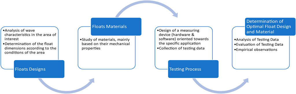
FIGURE 1. Process of selecting the optimal design and material for the floats.
In the design and development of wave energy devices, a systematic approach is necessary to ensure their efficiency and reliability. The process involves several essential steps, beginning with the examination of wave characteristics in the target area and subsequent determination of the appropriate dimensions and designs of the buoy to achieve beneficial performance (hydrodynamic behavior). In step two, various materials are assessed for constructing the floats, with their mechanical properties carefully examined to determine their suitability for the marine environment. The third step entails conducting experimental tests to evaluate the float designs and materials using a custom-designed measuring device and accompanying algorithm, despite the significant demands in terms of labor, resources, and cost. This testing process provides invaluable data critical for analyzing and determining the optimal float design and material in step four, based on the results and empirical observations during the testing phase. By following this systematic approach, we can develop wave energy devices that are efficient, reliable, and able to withstand the harsh conditions of the marine environment.
2.2 Hydrodynamic behavior of the buoys
The design of the floats in a wave energy harvester plays a crucial role in their buoyancy and ability to absorb energy from the waves. The aim of the design is to balance the support of the structure and the extraction of an optimal hydrodynamic shape that maximizes energy absorption from the waves. The hydrodynamic behavior of the floats is studied to determine the design that offers the best monitoring of the vertical movement of the waves, while minimizing stress on the structure and anchoring system. The float design specifications aim to extract an optimized shape that balances the extraction of energy from the waves and the stability of the structure. To optimize the performance of wave energy devices, several design considerations must be considered. Firstly, the floats should exhibit symmetrical behavior across multiple wave directions to ensure consistent energy absorption. Secondly, they should be capable of absorbing energy perpendicular to the direction of wave propagation to facilitate efficient energy transfer and conversion by the corresponding devices. Additionally, the floats should not sink or dissipate the energy of the wave in its direction of propagation, which can lead to increased structural stresses and reduced energy conversion efficiency. By carefully considering these design requirements, wave energy devices can be designed to operate effectively and reliably in real-world marine conditions.
An appropriate design and dimensioning require knowledge of the basic characteristics of waves, such as the period (T), the wavelength (λ) and the wave height (H). Since it's challenging to measure the wavelength empirically, it's first crucial to determine the wave period and sea depth in the area of interest using Eq. 1 (Rafael, 2008).
Equation 1: Dispersion relation for wavelength
The sea area under investigation possesses a wave period of 2 s and a depth of 37 m. The height of the waves in this area varies between 0.2 and 1.5 m, depending on meteorological conditions. By solving Eq. 1 and considering that the depth is 37 m which is translated as deep waters, the wavelength was calculated to be 6.1 m. To effectively interact with waves of these characteristics and harness their energy, a design proposal was made to utilize 2.4-meter diameter floats. The shipbuilding department of Glafcos Marine Ltd. Designed three different types of floats based on the described dimensioning, as described below.
• Floating buoy MD-V1: It has a circular shape with a diameter of 2.46 m and consists of four different levels, each of which has a height of 23 cm. The final height of the float is 0.95 m.
• Floating buoy MD-V2: It has a circular shape with a diameter at the upper end and at the lower end of 2.48 m and 1.06 m, respectively, while its final height is 0.80 m.
• Floating buoy MD-V3: It has a circular shape with a diameter at the upper end and at the lower end of 2.44 m and 2.19 m, respectively, while its final height is 0.56 m.
Although the wave period of the area under consideration may be limited, resulting in a relatively low amount of energy imparted by the waves, this does not constitute a constraining factor. This is due to the deployment of lightweight floating structures that exhibit a lower level of energy absorption. This approach affords a beneficial trade-off between performance and cost-effectiveness. Furthermore, the system can be easily expanded to accommodate higher energy levels while retaining a consistent relationship between cost and anticipated performance. Such a proportional escalation in expenses is crucial to ensure optimal performance across diverse designs.
2.3 Materials selection for the buoys
2.3.1 Examination of various materials for the construction of the buoys
In the initial study phase carried out for the design of the MD-V1, MD-V2, and MD-V3 floats, various possible materials were studied, which were considered as construction solutions that can satisfy both the functional requirements of the system and its financial parameter (acceptable cost). Several materials that are widely used in shipbuilding were examined. These are (1) glass reinforced plastic, (2) polyurea, (3) polyurethane, and (4) polystyrene.
Glass reinforced plastic (GRP) is a composite material consisting of a polymer matrix and glass fibers. The polymer matrix is usually plastic and provides the chemical properties to the product while the glass fibers add mechanical strength. As with many other composites, the two materials complement each other to form a stronger bond. By combining the two materials, GRP acquires high mechanical strength in both compressive and tensile forces. Production methods of GRP include yarn winding, centrifugal casting, hand laying and spray laying and evaporation. GRP has many positive technical features, such as low weight, high mechanical strength, high resistance to chemicals, high corrosion resistance and high resistance to UV radiation. GRP is waterproof and has a very long life (Kingsley Plastics Limited, 2022; Polymer Properties Database, 2022). Therefore, it is ideal for a wide range of applications, such as shipbuilding applications and of course the construction of floats. Polyurea is an elastomeric material whose elongation parameter is very high. Therefore, due to its high elasticity, the material exhibits high tensile strength. Polyurea is used in spray form and has excellent adhesion to many other materials. Other properties that distinguish it are very good crack bridging and impact resistance. The above makes polyurea a material of exceptional reliability for a multitude of applications such as the construction of floating shipyards. It is a material often chosen for the construction of floats (Polychem Systems, 2018; Behrouz et al., 2021; Polymer Properties Database, 2022). Polyurethane is a polymer found in a multitude of engineering applications. In offshore applications, urethane elastomers are the material of choice in many applications due to the advantages of its application. Some of them are the low water absorption, resistance to salt water, stable behavior in UV radiation, resistance to the growth of algae and fungi, resistance to oxidation even after long-term exposure to water and harsh environments and good mechanical properties (Matmach, 2022; Polymer Properties Database, 2022). These characteristics, as well as the fact that polyurethane responds very often to the use of floats in other applications, make it an additional material to study. Polystyrene is a clear, amorphous, non-polar thermoplastic product that is easy to process and can easily be converted into many semi-finished products such as foams, films and sheets. It is also easy to manufacture into many finished products, as it is a viscous liquid above the glass transition temperature that can be easily molded is often preferred for high volume components. Some of its weaknesses can be overcome by copolymerization with other monomers. Polycopolymer (styrene-co-methyl methacrylate) has higher clarity and improved chemical and UV stability. Polystyrene is a non-biodegradable plastic and resistant to photolysis. Polystyrene is a polymer that is cheap and easy to process. It is the material of choice for many applications, including food packaging, single-use plastics, and components for optical, electronic/electrical, and medical applications. A wide variety of products are formed by injection molding (Polymer Properties Database, 2022). Also, iron (black sheet metal) and aluminum were examined as possible construction materials for the floats but due to the unique design of floats issues arose.
2.3.2 Determination of the optimal material for the buoys
The selection of the optimal material for the buoys is crucial for the efficient absorption of wave energy. The material must possess specific mechanical and physical properties that allow for the buoys to effectively interact with the waves, withstand harsh oceanic conditions, and have a minimal environmental impact. To ensure optimal performance, a thorough evaluation of various materials must be conducted. This involves considering factors such as durability, cost-effectiveness, and sustainability.
Comparison among the materials show that irons’ machining (curving and welding) is extremely difficult due to the high complexity and relatively small dimensions of the floats. Such a specialized construction requires sheet metal of different thicknesses, great care in assembly and ultimately a dubious result in terms of waterproofing and hydrodynamics of the construction. Also, aluminum, although it can undergo precision machining relatively easier, has a prohibitive cost. To do so, these materials were rejected. Polystyrene has similar properties to polyurea and polyurethane in terms of buoyancy and hydrodynamic behavior (friction during fluid-solid interaction). However, it has a lower specific weight and clearly worse mechanical properties, which make it unsuitable for a long-term application in a marine environment. Nevertheless, it was judged as a useful alternative for the comparative study between different designs of floats during the experimental process, due to its ease of transport and pointing. However, it has a lower specific weight and clearly worse mechanical properties, which make it unsuitable for a long-term application in a marine environment. It should be noted that regarding the plastic materials—fiberglass plastic, polyurea, polyurethane and polystyrene, they were expected to have similar hydrodynamic behavior, but not similar mechanical properties. To do so, GRP the usual practice of constructing boats from this material is in sections using suitable molds. However, due to the limited volume and detail of the construction and after constant communication with the manufacturer, it was decided to implement the floats, through a construction process from the inside out. More specifically, an expanded polystyrene matrix will be used, which will be pantograph cut (CNC) to precisely achieve the specific designs. The pantograph cutting process allows for precise shaping of the master pattern of buoy, which in turn ensures that the polysterene matrix is accurately shaped. Once the matrix is created, it can be used as a mold for creating the buoys made from polyester and the two other materials. The mold is typically filled with a liquid mixture of the materials, which is then allowed to harden and cure. Once the mixture has hardened, it can be removed from the mold, and any excess material can be trimmed away. The materials are polyurea and polyurethane, and are prompts of experienced builders, as they apply to lightweight floating structures, which are manufactured by spraying on a matrix.
The issue of lower specific weight was solved by adding wooden blocks of 80 kg total per float, plus ballast, to achieve a comparable draft to floats of the other materials. The weight and therefore the draft is a dominant parameter that determines their kinematic behavior, in addition to the design, therefore, for the comparative and objective evaluation of the designs, the existence of a corresponding draft was necessary.
3 Test analysis and results
To validate the proposed designs and materials, it is crucial to conduct experiments under real conditions. Therefore, experimental testing is necessary to confirm the effectiveness and reliability of the designs and materials. The experiments should be conducted in a controlled and systematic manner, with appropriate measurements and data collection procedures to ensure accurate and consistent results. Also, they can reveal unexpected behavior or limitations of the proposed designs and materials, leading to further refinement and optimization. Overall, experimental testing is an essential step in the design and development of new technologies, providing empirical evidence of their performance and enabling their successful deployment in real-world applications.
3.1 Design of the measuring device
Experimental testing of wave energy devices at sea is essential to evaluate their performance and optimize their design. Developing reliable and accurate measuring devices is a crucial step in the experimental testing of wave energy devices at sea. The measuring devices are essential for capturing critical data on the behavior of floats, including their vertical displacement, angular deviation from the horizontal position, and absorbed power, among other parameters. The design of these measuring devices should be carefully considered, taking into account the specific requirements of the marine area of interest and the characteristics of the wave energy device. Once the measuring devices have been designed and optimized, they must be tested under real conditions to evaluate their performance and reliability. The devices should be carefully placed on the floats to ensure that the measurements are accurate and consistent. By evaluating the measured results, it is possible to assess the efficacy of the measuring devices and refine their design as necessary. Only then can the full potential of wave energy devices be realized through experimental testing that produces reliable and accurate data.
Waves act as a source of velocity and ripples are composed of oscillations, so floats perform forced oscillations. The oscillating energy performed by each float is a function of its vertical displacement. Therefore, by measuring the displacement, the magnitude of the absorbed energy is qualitatively estimated, in the conditions in which the experiment is to be carried out.
3.1.1 Hardware
Glafcos Marine Ltd. Has designed and produced an in-house measuring device that is tailored to its specific application. The device incorporates specialized sensors, such as accelerometers and gyroscopes, which are highly sensitive to movement. The use of ultrasonic type sensors, which rely on triangulation, is not feasible due to the unrestricted movement of the floats. Additionally, barometers are not suitable for the experiment’s relatively small displacements, resulting in poor response. The device’s measurements are collected via a microcontroller with a sampling period of 25 milliseconds. The device records (1) acceleration in the three body-bound axes of the accelerometer in g, (2) the time elapsed since the start of the measurements in milliseconds, and (3) angular velocities (deg/s) from the gyroscope on their three body-bound axes, which are the same as those of the accelerometer. The measurements are stored on a micro-SD card via an SD MODULE. The device operates autonomously using a 9 V battery, and an LED is included to indicate whether the device is operating correctly. The electronic components are mounted on an 8 × 6 cm punched board. The electrical diagram is presented in Figure 2.
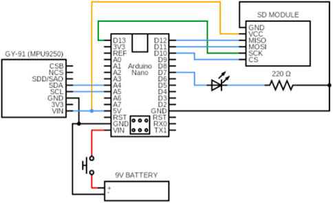
FIGURE 2. Electrical diagram of measuring device.
The measuring device uses an Arduino Nano clone as a microcontroller, which is open source, small (18 × 45 mm), and light (5–7 g). The main IMU sensor is the MPU6050 (16bit), which integrates an accelerometer and a gyroscope on the same chip. The sensitivity and accuracy of the Arduino Nano and MPU6050 exceed the needs of the experiment.
3.1.2 Software
The primary objective of the measuring device is to determine the kinematic behavior of the floats, specifically their vertical displacement and angular deviations in pitch and yaw relative to the horizontal plane. The device’s programming utilizes the Arduino Nano microcontroller and the official Arduino Integrated Development Environment, which is written in C and C++ and provides flexibility in utilizing various libraries to optimize the MPU6050 sensor’s performance, accelerate data recording onto the micro-SD, and optimize communication between the electronics. MATLAB is used for data processing due to its high-level programming language, which is suitable for modeling, simulation, prototyping, data analysis, and result visualization, among other applications. The algorithm developed for data processing involves integrating the angular velocity and double integrating the acceleration data. The algorithm’s efficiency is due to MATLAB’s rapid array/vector operation algorithms, which are crucial for handling large arrays in the proposed system.
Data is imported into MATLAB in an Nx7 array, where N represents the number of measurements. The six measurements include three linear accelerations
The denoising process is illustrated in Figure 3, with a cut-off frequency of 1 Hz used to filter the wave signal recorded during the device’s pilot operation. The filtered signal is shown in red, while the raw signal is shown in blue.
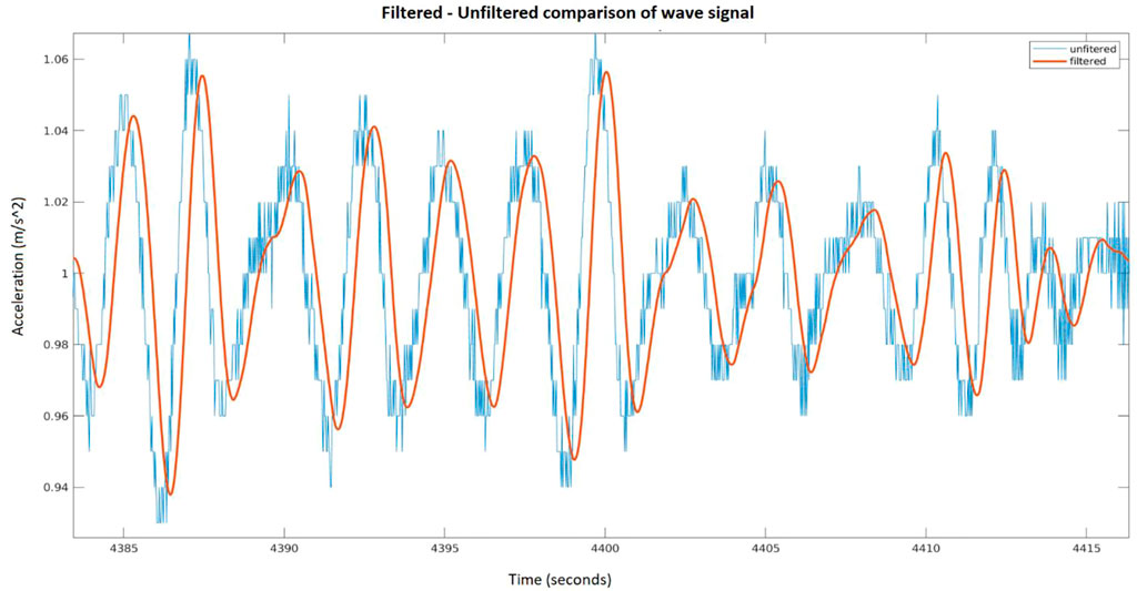
FIGURE 3. Denoising of the wave signal with a cut-off frequency of 1 Hz.
The subsequent task entailed computing the vertical acceleration and angular displacement, following the determination of the rotation of the float’s coordinate system, fully defined by the angular velocities ω𝑥, ω𝑦, ω𝑧 captured by the sensors. Initially, the body-bound coordinate system
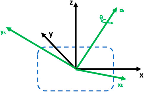
FIGURE 4. Sketch of device and coordinate systems.
The proposed approach’s advantage is that it requires a single integration of the recommended angular velocity, as opposed to three in alternative techniques. Thus, determining the angle θ and the axis
Equation 2: Rotation matrix 0R1
The first term is
If N measurements have been taken and N rotations have been made, the rotation of the final coordinate system with respect to the initial (global) coordinate system can be calculated by successively multiplying the rotation matrices between the intermediate systems (Eq. 3).
Equation 3: Rotation of the final coordinate system with respect to the initial (global).
The equivalent axis of rotation is a unit vector in the direction of the angular velocity. Finding the equivalent axis of rotation follows from the angular velocity components as follows:
With,
The equivalent angle θ is determined through the integration of the equivalent angular velocity. However, integration is not performed over the entire signal length, but rather in each sampling interval separately. This is because the resulting angles indicate the relative rotation of the SS between two consecutive measurements, which does not necessarily occur around the same equivalent axis. Thus, the relative angle at the beginning of each integration is 0 radians (0°). With the equivalent angle and equivalent axis at each measurement, it becomes possible to calculate the rotation matrix at each time instant. As a result, a complete picture of the float’s angular deviation from the horizontal plane can be obtained, and the vertical acceleration can be determined. To obtain the acceleration in the
3.1.2.1 Evaluation of sensing device
In this paragraph the tests carried out in a controlled environment and in real wave conditions to evaluate the sensing device are presented. The tests examined the ability of the measuring device/algorithm to find the recommended vertical acceleration/displacement, as a function of three parameters:
1. Change in oscillation amplitude (70 cm, 35 cm, and 15 cm), where the sensor measurements with the help of the algorithm developed in the project returned quite satisfactory results (Figure 5).
2. Change in the frequency of oscillation and perform periodic movement of the device over a path of 50–70 cm (Figure 6).
3. Change in sensor orientation, as would occur in real sea wave conditions, keeping the amplitude of the oscillation constant. It was found that the developed algorithm can successfully extract the vertical displacement of the sensor, regardless of its orientation (Figure 7).
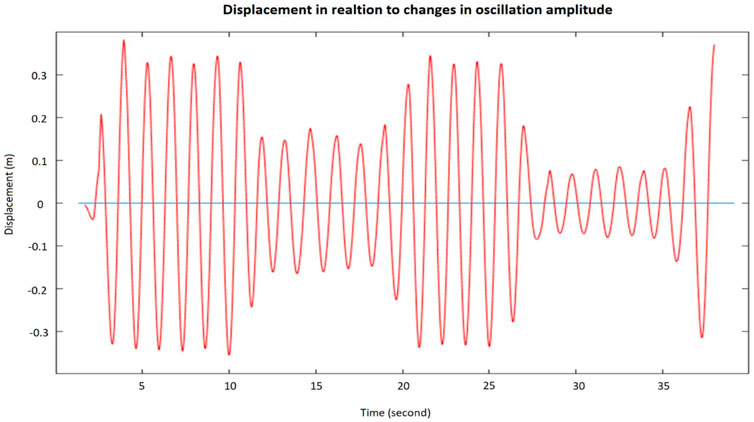
FIGURE 5. Changes in oscillation amplitude (70 cm, 35 cm, and 15 cm).
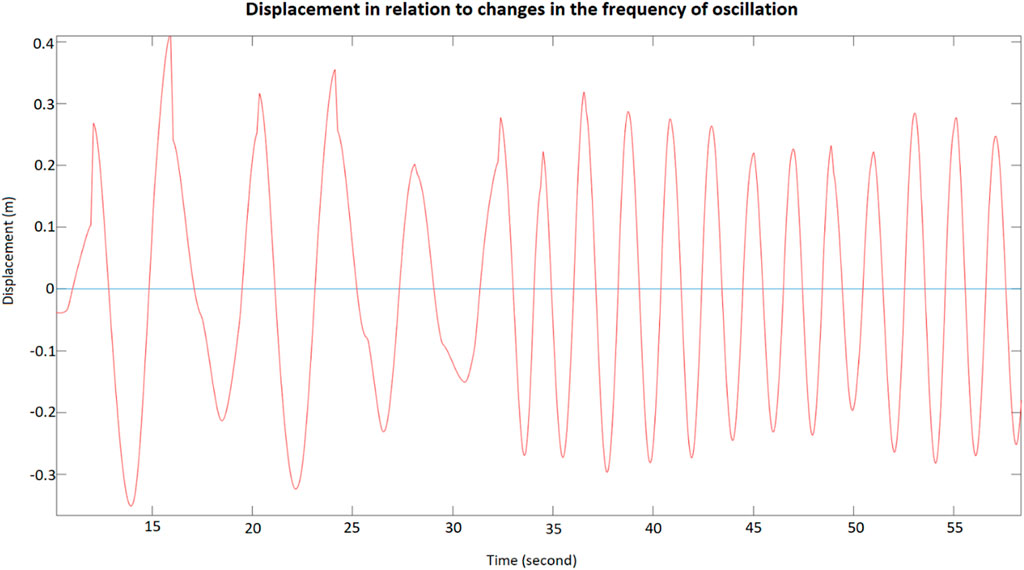
FIGURE 6. Changes in the frequency of oscillation.
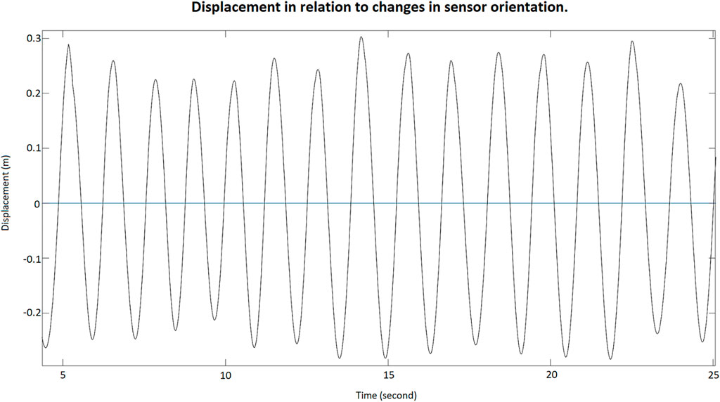
FIGURE 7. Changes in sensor orientation.
After obtaining satisfactory results in controlled conditions, tests were carried out in real conditions. A measuring device was placed in a sealed container, capable of floating, and placed at two points along the Piraeus. According to the website https://www.windy.com, the average wave height expected, ranged approximately between 10 cm (amplitude 5 cm) (according to the ECMWF forecast model) and 30 cm (amplitude 15 cm) (according to the ICON-EU model). The received data confirm the prediction models (Figure 8).
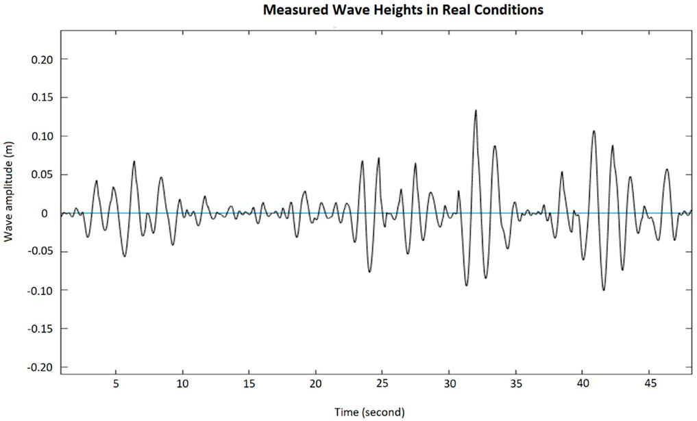
FIGURE 8. Measured wave heights in real conditions.
3.2 Procedure for testing the floats
The experimental procedure for testing the floating wave harvester involved the strategic positioning of a series of floats at approximately 80–100 m from the shipyard dock. The floats were tethered together in pairs and trios using a 5-meter rope and were towed to their desired location by boat, as illustrated in Figure 9. To ensure the appropriate level of tension and prevent any hindrance to the floats’ vertical movement, skilled divers were tasked with securing one end of the floats to an existing mooring line using a 15-meter rope, while the other end was attached to a boat. Before conducting the experiment, the measuring devices were meticulously placed on the floats, and the floats were preheated for 10 min and calibrated to accurately parameterize the system. The experimental procedure involved repeated data collections every two (2) hours and 15 min, and the process was repeated on two different days to ensure the validity of the results (Figures 10, 11). Overall, the experimental setup was designed to ensure that the testing environment was controlled, and the data collected was accurate and reliable.
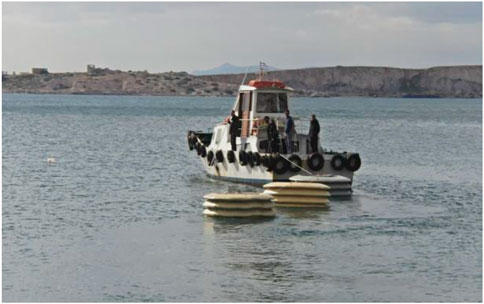
FIGURE 9. Transportation of floats using a tow boat.
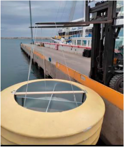
FIGURE 10. Sinking floats.
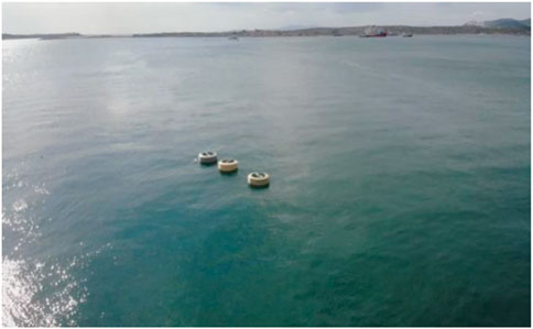
FIGURE 11. Snapshot from the first day of the experiment.
3.3 Analysis of the experimental data
From the data collected, it was found that the actual sampling period was
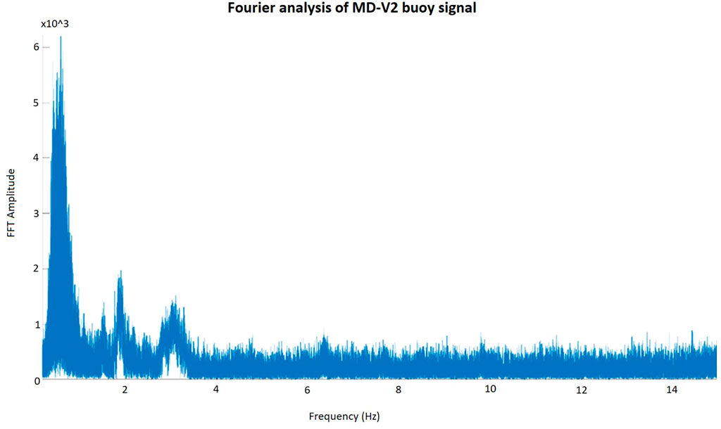
FIGURE 12. Fourier analysis of MD-V2 buoy signal.
Denoising is performed by a second-order Butterworth deep-pass filter, with a cut-off frequency of fc = 0.8 Hz. This process rejects high-frequency noise, as well as waves with negligible amounts of energy. However, during the 2 h, the wave conditions were not uniform. Consequently, at some moments in time the floats received a wave of relatively low energy (Figure 13) and in others higher energy ripple (Figure 14). Therefore, conclusions can be drawn about their behavior in a multitude of wave heights.
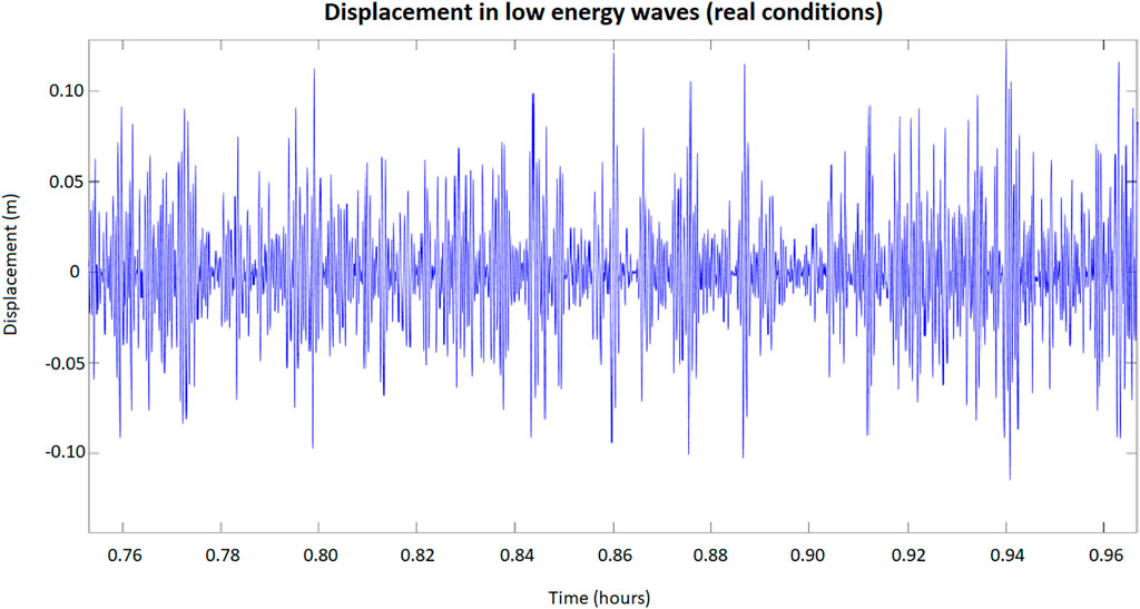
FIGURE 13. Displacement in low energy waves (real conditions).
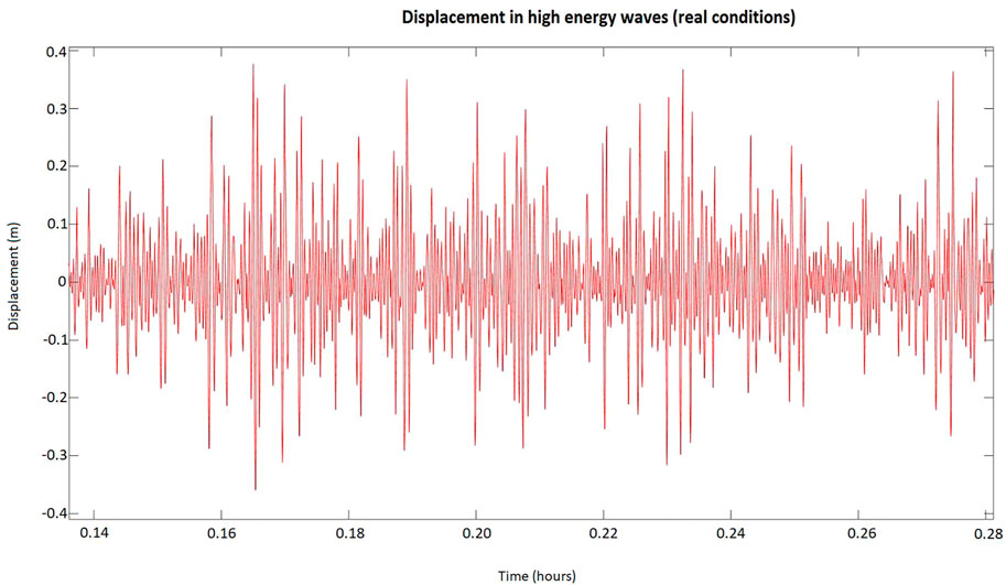
FIGURE 14. High energy waves.
3.4 Evaluation of the float designs and materials based on the experimental results
The deployment of wave energy converters (WECs) in the open sea requires the design and optimization of floating devices that can effectively extract energy from the waves. Floats are commonly used as they have demonstrated good performance in a variety of wave conditions. However, there is a need to compare the behavior of different types of floats in terms of their vertical lift, angular deviations, and absorbed power. In this regard, a study was conducted to compare the behavior of three different conical floats (MD-V1, MD-V2, and MD-V3) in a wave tank under regular wave conditions. The study analyzed the vertical displacement (H1/3), angular deviations from the horizontal position (
Vertical displacement in accordance with considerable height (H1/3) is an important factor for determining the behavior and it is defined as the average of the first 1/3 of the sorted displacements (Eq. 4).
Equation 4: Calculation of vertical displacement
Where i is the rank number of displacements in descending order (Hi > Hi+1).
One important factor to consider when selecting floats is their deviation from the horizontal plane, which is determined by measuring their angular displacement (
Finally, the absorbed power of the floats is given by Eq. 5.
Equation 5: Calculation of absorbed power where,
When comparing the performance of different conical floats in terms of their vertical displacement, it is evident from Table 1, that MD-V3 exhibits the poorest behavior with a vertical lift of only 24.45 cm. On the other hand, MD-V1 performs the best, exhibiting superior behavior in terms of vertical lift, as it can effectively track waves, resulting in maximum lift and consequently faster power generation. This is due to the float’s design, which enables it to efficiently follow the wave. In terms of angular deviations from the horizontal flat position (
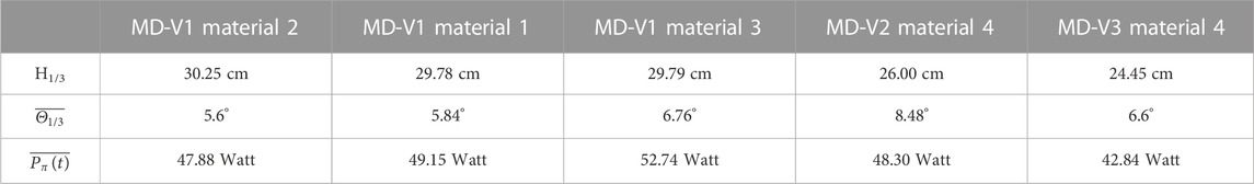
TABLE 1. Experimental results for different designs and materials.
The present study evaluated various materials for the manufacturing of floats based on their mechanical properties, ease of manufacture, and cost. The evaluation process involved visual observations, as well as testing under various stresses such as impacts on the dock of the shipyard, on the lance, and drill testing using a screwdriver and impact drill. Based on the results of these tests, it was determined that polyurea exhibits superior stress resistance and is less prone to deformation compared to polyurethane. Furthermore, it was found to be more elastic and less rigid than glass-reinforced plastic (GRP), which can crack or break under stress. As a result, polyurea was deemed to be the optimal material for float manufacturing. Moreover, the evaluation of different float designs indicated that the MD-V1 float is the optimal design when considering the criteria of vertical lift, tracking of waves, angular deviations from the horizontal flat position, and absorbed power. Hence, the combination of the MD-V1 float design and polyurea as the material of choice is recommended for future float manufacturing endeavors.
4 Conclusion
This paper presents the development phases and the conceptual design of a new floating harvester as a solution to harvest the energy from ocean waves. The process of determining the buoys’ shape and material of construction is the subject of the paper. These factors are crucial to the system’s success because they have a major impact on the system’s dynamic behavior, the ability to absorb energy, and the ability to convert the kinetic energy of the waves into direct and indirect usable electrical energy. The methodology followed is governed by the philosophy of the gradual development of the individual parts, choosing the best solution at each step, and using the result in the next step. The main objective of the study carried out concerns the definition of the optimal layout and construction material that ensures:
• Robustness, to respond to the stresses during its installation in the marine environment and the forces resulting from the interaction between floats and waves.
• Elasticity, to minimize the possibility of damage to the structure and to better absorb the energy from the movement of the floats.
• Simplicity and symmetry, to minimize the cost of construction (mainly during its transition as an industrial product) and to make the expansion of existing systems immediate.
Three main floats designs (MD-V1, MD-V2, and MD-V3) were developed and assessed through experiments in real conditions. The results show that the MD-V1 design is the most appropriate in terms of vertical displacement, angular deviations from the horizontal flat position and absorbed power, as it showed the best behavior and interaction with the ripple. Additionally, in relation to the various materials, iron and aluminum were rejected because of the difficulties in curving and welding due to the high complexity and relatively small dimensions of the floats, and high cost of construction. So, different types of plastids were examined - Polyurea, Polyurethane, GRP and Polystyrene. These materials have excellent mechanical properties, such as mechanical strength, high resistance to chemicals, resistance to salt water, stable behavior in UV radiation, etc., and low construction cost. Among them polyurea was found to be superior in terms of stress resistance, difficulty in deformation and elasticity.
In conclusion, the experimental testing of the floating wave energy harvester under real conditions has demonstrated the efficacy of the proposed designs and materials. The use of reliable and accurate measuring arrangements was crucial for collecting critical data on the floats’ behavior, such as their vertical displacement, angular deviation from the horizontal position, and absorbed power. The experimental results have identified areas for improvement. Further refinements and optimizations can be made by analyzing the collected data and comparing it with simulated data to enhance the energy conversion efficiency of the floats. The successful experimental testing has provided empirical evidence of the device’s performance, enabling its deployment in real-world applications. The next goal of our research is to the detailed study of the optimal choice of method/technique to convert the absorbed wave energy from the system designed, into electrical energy. The evaluation criteria concern both the performance of the method in the conversion to electricity and the risks involved.
The design, development, and deployment of the wave energy conversion system described in the previous sections faced several challenges and limitations. One of the major challenges was related to the design of the floats, which had to be optimized in terms of shape, size, and material properties to maximize the energy conversion efficiency and minimize the cost of production. This required extensive experimentation and testing, as well as the use of advanced tools to predict the performance of different designs under varying wave conditions. Another challenge was related to the deployment of the floats, which had to be done in harsh marine environments with strong currents, waves, and wind. This required the use of specialized vessels and equipment to transport, deploy, and maintain the floats, as well as the development of robust mooring systems to keep them in place and prevent them from drifting or capsizing.
The measurement and analysis of the data collected by the sensors on the floats was also a challenging task, as it required the development of advanced signal processing algorithms to filter out noise and extract meaningful information from the complex and variable signals. Moreover, the interpretation of the data and the identification of the factors that affect the performance of the floats were complicated by the non-linear and dynamic nature of the wave energy conversion process.
Finally, the cost of production and deployment of the system had to be competitive with other renewable energy sources such as wind and solar power. This required the optimization of the materials and manufacturing processes used in the production of the floats, as well as the development of cost-effective deployment and maintenance procedures.
Future work should focus on the optimization of the floating wave energy harvester based on the data collected from the experimental testing. Refinements can be made to the design and materials of the floats to improve their performance and energy conversion efficiency. Additionally, the effect of different environmental conditions, such as changes in wave height and frequency, should be evaluated to determine the device’s adaptability to varying oceanic conditions. The development of advanced measuring arrangements can enhance the accuracy and reliability of the data collected during the experimental testing, providing valuable insights into the behavior of the floating wave energy device. The deployment of the optimized device in real-world applications can lead to the widespread adoption of wave energy as a sustainable source of renewable energy.
Data availability statement
The original contributions presented in the study are included in the article/supplementary material, further inquiries can be directed to the corresponding author.
Author contributions
AD: Conceptualization, methodology, investigation, formal analysis, visualization, writing—original draft. LD: Conceptualization, supervision, project administration
Funding
This research has been co-financed by the European Union and Greek national funds through the Operational Program Competitiveness, Entrepreneurship, and Innovation, under the call RESEARCH—CREATE—INNOVATE (project code: T2EDK-04256).
Conflict of interest
Authors AD and LD was employed by the company Glafcos Marine Ltd.
Publisher’s note
All claims expressed in this article are solely those of the authors and do not necessarily represent those of their affiliated organizations, or those of the publisher, the editors and the reviewers. Any product that may be evaluated in this article, or claim that may be made by its manufacturer, is not guaranteed or endorsed by the publisher.
References
Aderinto, T., and Li, H. (2018). Ocean Wave energy converters: Status and challenges. Energies 11, 1–26. doi:10.3390/en11051250
Al Shami, E., Zhang, R., and Wang, X. (2019). Point absorber wave energy harvesters: A review of recent developments. Energies 12. doi:10.3390/en12010047
Behrouz, S., Mohammad, N., Yazdanbakhsh, A., Mojtaba, A., Chunwei, Z., and Zhang, C. (2021). A review on the applications of polyurea in the construction industry. Polym. Adv. Technol. 32, 2797–2812. doi:10.1002/pat.5277
Bhuyan, G. S. (2010). World-wide status for harnessing ocean renewable resources. IEEE PES Gen. Meet. PES 2010, 26–28. doi:10.1109/PES.2010.5589292
Clemente, D., Rosa-Santos, P., and Taveira-Pinto, F. (2021). On the potential synergies and applications of wave energy converters: A review. Renew. Sustain. Energy Rev. 135, 110162. doi:10.1016/j.rser.2020.110162
Curto, D., Viola, A., Franzitta, V., Trapanese, M., and Cardona, F. (2020). A new solution for sea wave energy harvesting, the proposal of an ironless linear generator. J. Mar. Sci. Eng. 8, 93. doi:10.3390/jmse8020093
Dincer, I. (2000). Renewable energy and sustainable development: A crucial review. Renew. Sustain. energy Rev. 4, 157–175. doi:10.1016/S1364-0321(99)00011-8
Drew, B., Plummer, A. R., and Sahinkaya, M. N. (2009). A review of wave energy converter technology. Proc. Inst. Mech. Eng. Part A J. Power Energy 223, 887–902. doi:10.1243/09576509JPE782
EU (2021). 2030 climate and energy framework. Available at: https://climate.ec.europa.eu/eu-action/climate-strategies-targets/2030-climate-energy-framework_en (Accessed October 20, 2022).
Falcão, A. F. d. O. (2010). Wave energy utilization: A review of the technologies. Renew. Sustain. Energy Rev. 14, 899–918. doi:10.1016/j.rser.2009.11.003
Garcia-Teruel, A., and Forehand, D. I. M. (2021). A review of geometry optimisation of wave energy converters. Renew. Sustain. Energy Rev. 139, 110593. doi:10.1016/j.rser.2020.110593
Guo, B., and Ringwood, J. V. (2021). A review of wave energy technology from a research and commercial perspective. IET Renew. Power Gener. 15, 3065–3090. doi:10.1049/rpg2.12302
Hota, R. K., and Kumar, C. S. (2022). “Derivation of the rotation matrix for an axis-angle rotation based on an intuitive interpretation of the rotation matrix,” in Machines (Mechanism and Robotics), 939–945.
Huang, B., Wang, P., Wang, L., Yang, S., and Wu, D. (2020). Recent advances in ocean wave energy harvesting by triboelectric nanogenerator: An overview. Nanotechnol. Rev. 9, 716–735. doi:10.1515/ntrev-2020-0055
Isaacs, J. D., Castel, D., and Wick, G. L. (1976). Utilization of the energy in ocean waves. Ocean. Eng. 3, 175–187. doi:10.1016/0029-8018(76)90022-6
Khairallah, C., Eid, E., Rahme, P., and Bou-Mosleh, C. (2019). “Development of a wave buoy device for energy harvesting: Renewable energy,” in 2019 4th int. Conf. Adv. Comput. Tools eng. Appl. ACTEA 2019. doi:10.1109/ACTEA.2019.8851089
Kingsley Plastics Limited (2022). Properties of GRP. Available at: https://www.kingsleyplastics.co.uk/articles/properties-of-grp/ (Accessed September 15, 2022).
Leijon, M., Danielsson, O., Eriksson, M., Thorburn, K., Bernhoff, H., Isberg, J., et al. (2006). An electrical approach to wave energy conversion. Renew. Energy 31, 1309–1319. doi:10.1016/j.renene.2005.07.009
Li, Y., Ma, X., Tang, T., Zha, F., Chen, Z., Liu, H., et al. (2022). High-efficient built-in wave energy harvesting technology: From laboratory to open ocean test. Appl. Energy 322, 119498. doi:10.1016/j.apenergy.2022.119498
Matmach (2022). Polyurethane: Properties, processing, and applications. Available at: https://matmatch.com/learn/material/polyurethane (Accessed September 15, 2022).
Mehrangiz, S., Emami, Y., Sadigh, S. H. S., and Etemadi, A. (2013). Various technologies for producing energy from wave: A review. Int. J. Smart Grid Clean. Energy 2, 289–294. doi:10.12720/sgce.2.2.289-294
Owusu, P. A., and Asumadu-Sarkodie, S. (2016). A review of renewable energy sources, sustainability issues and climate change mitigation. Cogent Eng. 3, 1167990. doi:10.1080/23311916.2016.1167990
Polychem Systems (2018). Properties and application of polyurea. Available at: https://www.polychem-systems.com.pl/en/akademia/properties-and-application-of-the-polyureas/ (Accessed September 15, 2022).
Polymer Properties Database (2022). Polymer properties database. Available at: https://polymerdatabase.com/polymerclasses/Polyurethane type.html (Accessed September 15, 2022).
Rafael, W. (2008). “Full scale experimental verification of a wave energy converter,” in Energy from ocean waves (acta universitatis upsaliensis uppsala), 132.
Keywords: renewable energy sources, wave energy, floating harvester, harvester specifications, system interconnection
Citation: Deligianni A and Drikos L (2023) Floating wave energy harvester: a new perspective. Front. Energy Res. 11:1122154. doi: 10.3389/fenrg.2023.1122154
Received: 12 December 2022; Accepted: 13 April 2023;
Published: 26 April 2023.
Edited by:
Weichao Shi, University of Strathclyde, United KingdomReviewed by:
Aspasia Pastra, World Maritime University, SwedenYasin Kaan Ilter, University of Strathclyde, United Kingdom
Copyright © 2023 Deligianni and Drikos. This is an open-access article distributed under the terms of the Creative Commons Attribution License (CC BY). The use, distribution or reproduction in other forums is permitted, provided the original author(s) and the copyright owner(s) are credited and that the original publication in this journal is cited, in accordance with accepted academic practice. No use, distribution or reproduction is permitted which does not comply with these terms.
*Correspondence: Leonidas Drikos, bGVvZHJpa29zQGdsYWZjb3MtbWFyaW5lLmNvbQ==