 Guosheng Yang1
 Yujia Zhu
 Xiaolong Chen
- 1State Key Laboratory of Power Grid Security and Energy Conservation, China Electric Power Research Institute, Beijing, China
- 2State Grid Corporation of China, Beijing, China
- 3Key Laboratory of Smart Grid of Ministry of Education Tianjin University, Tianjin, China
The low voltage ride-through (LVRT) requirements demand large-scale photovoltaic (PV) power generation system remain connected to the grid during faults. It results in considerable impact on the characteristics of fault current. This paper combines charge-discharge characteristics of the energy storage (ES) with PV generation system to enhance the LVRT capability. Based on the inverter control strategy and specific LVRT requirements, fault current characteristics of the PV-ES power generation system is discussed in this paper. In order to analyze the fault characteristic, the fault current expression as three-phase short-circuit faults occurs on both sides of the main transformer is calculated. Furthermore, taking the winding connection of the transformer into account, the ratio of differential current to braking current is further derived to find out the factors influencing the performance of the transformer differential protection. It is found that factors influencing the transformer differential protection include the rated capacity of the PV-ES generation system, fault severity, the length of transmission line and so on. And as the rated capacity of the PV-ES power generation system increase, the transformer differential protection would experience reduced sensitivity or even do not trip. The findings of this paper can lay a foundation for further improvement of the transformer differential protection. The elaborate performance evaluation of transformer differential protection, including the operation condition of the second harmonic braking element, is presented and verified by simulation using MATLAB/Simulink.
1 Introduction
Nowadays, more and more PV generation systems have been connected to the power grid. Most of the countries are committed to increase the use of renewable energy, and the installed capacity of PVs is increasing year by year (Das et al., 2018). In 2021, the new installed capacity of PVs has reached 170 GW, and more than 140 countries and regions have proposed carbon neutrality goals. PV installations are expected to grow by around 30% year-on-year to 200–220 GW in 2022.
In recent years, there have been many researches on the fault analysis of IIDG (Baran and El-Markaby, 2005; Boutsika and Papathanassiou, 2008; Liu et al., 2017), and some improved protection methods (Nimpitiwan et al., 2007; Perpinias et al., 2015; Wang et al., 2015; Cohen and Callaway, 2016; Gao et al., 2017) have been proposed. For example, a new short-circuit current calculation method for IIDGs has been proposed, which can determine the short-circuit current of a multi-IIDG distribution network regarding the ride-through time and sequence current control (Wang et al., 2015). The high penetration of IIDGs brings new characteristics to grid, such as multisource, multibranch, bidirectional power and fault current flow, as well as weak infeed (Gao et al., 2017). Yet, as centralized inverter-interfaced generation systems, the GCPPPs inherit some of the above characteristics, but also have some own peculiarities.
On the one hand, the capacity of GCPPPs usually up to the order of several hundred megawatts, resulting in their non-negligible proportions of the generation in the transmission networks (Hooshyar et al., 2015). On the other hand, as the increasing capacity of GCPPPs, the need for these plants to be more effective contributors to keep the stability, operability, and reliability of the power grid increases (Almeida et al., 2016; Al-Shetwi et al., 2019; Haidar et al., 2022). In line with this, many countries have proposed PV grid-connected specifications, clarifying the requirements that GCPPPs need to remain connected to the grid and provide reactive power support to the grid during grid faults. These requirements in modern GCs are defined as LVRT requirements (Neumann and Erlich, 2012). However, due to the reduction of the active power demand of the power grid during LVRT, the input power and output power on the DC-link are unbalanced. It will lead to a sharp increase in the DC-link voltage of the PV power system, which will affect the safety of the inverter. Literature (Al-Shetwi et al., 2019) has presented an overview and comparison of several LVRT capability enhancement approaches during grid fault conditions. Among those approaches, the LVRT capability improvement utilizing ESSs is adopted in this paper, which is the common solution to mitigate the PV systems generated power variability (Al-Hilfi et al., 2021). Since the ESSs have the feature of absorbing and releasing energy, the problem of overvoltage on DC-link can be well improved by connecting the ESSs to the DC-link through the buck-boost DC-DC converter. In the case that the DC-link voltage can be considered as nearly constant, the control of inverter can be considered as decoupled with generator side (Alepuz et al., 2009). So, the fault current characteristics of PV side mainly depend on the control strategy of the inverter and the modern GCs employed.
Many studies have analyzed some fault current characteristics of GCPPPs, but most of them are studies on the fault analysis of the transmission line of GCPPPs and focus on line protection (Jia et al., 2018; Alsafasfeh et al., 2019; Liang et al., 2020). Both (Alsafasfeh et al., 2019; Jia et al., 2018) have calculated expressions of fault current under different control targets, which are suppressing negative sequence current, suppressing active power fluctuation and suppressing reactive power fluctuation respectively. Literature (Alsafasfeh et al., 2019) has discussed applicability of phase selector, and analyzed the relationship between the difference and the sequence component of phase current considering different control aims. In literature (Jia et al., 2018), the performance of the overcurrent relay within the collection station of an 850 MW GCPPP was evaluated, and a new relay protection design with directional distance elements was proposed, supported by the fault current analysis. Literature (Jia et al., 2018) has derived the ratio of differential current over restraint current based on the fault current characteristics, and drawn conclusions that the current phase angle difference might cause maloperation of the current differential protection for transmission line. However, all of them did not take the effect of actual LVRT requirements on the fault current characteristics of PV systems into account.
In the meantime, the analysis of fault characteristics of the main transformer in the transmission network involved GCPPPs needs to be further improved. The mechanism of second harmonic generation of GCPPPs during grid faults and its impact on transformer protection has been analyzed in (Wang et al., 2020). However, the simulation results of paper (Wang et al., 2020) shows that only when the SCR is very low that the percentage second harmonic of differential current would consistently be above threshold during the fault. And second harmonic braking element is just a part of the transformer main protection. The impact of GCPPPs on the entire main protection of the transformer needs to be further analyzed. Literature (Jin et al., 2020) offered the view that the output current of GCPPPs during grid faults would probably lead the decreasing sensitivity of transformer differential protection, but lack of corresponding theoretical analysis.
This paper comprehensively evaluates the performance of the differential protection for the main transformer in the PV-ES power plant when symmetrical faults occur in the protection zone of the main transformer. The ratio of differential current over braking current has been mathematically calculated and analyzed, based on the LVRT requirements in Chinese latest GCs and the control strategy of the grid-connected inverter. To determine the actual change trend of the ratio, the phase angle of the grid voltage is further derived, and the factors influencing the performance of the transformer differential protection are found out comprehensively. Finally, by combining the second harmonic component of fault currents and the change of the ratio of differential current over braking current in the simulation results, a complete transformer differential protection applicability analysis is obtained.
The remaining parts of this paper are organized as follows. Section 2 describes the topology of the PV-ES power plant under study, and discusses the characteristics of the output current of the PV-ES power generation system during symmetrical faults on both sides of the main transformer. The fault analysis of the three-phase short-circuit faults on the both ends of the main transformer is carried out in Section 3, on the basis of the ratio braking principle of the transformer differential protection. And Section 4 discusses the impact of the PV-ES power generation system access on the protection of the main transformer under three-phase short-circuit faults. Simulation results and validation by comparing theoretical analysis are in Section 5. Finally, conclusions are presented in Section 6.
2 Fault current characteristics of the PV-ES power generation system
2.1 Overview of the photovoltaic-energy storage power plant
The topology of PV-ES power generation system under study is illustrated in Figure 1. A number of PV-ES units in the PV-ES power generation system are each connected in parallel to the PCC, which is also the 35 kV bus, through a grid-connected transformer. And then the PCC is connected to the low-voltage side of the main transformer, while the high-voltage side of the main transformer connecting to the 110 kV system through the transmission line. Typically, either grid-connected transformer or main transformer is YNd11 connection.
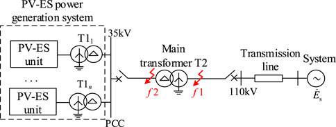
FIGURE 1. Topology of the PV-ES power generation system.
The inner structure of the PV-ES unit is showed in Figure 2. Within the PV-ES unit, the battery is connected to the DC-link through the bidirectional DC-DC converter. Its function is to suppress the fluctuation of the DC-link voltage and improve the LVRT capability by protecting the DC-link and inverter from an overvoltage during grid faults (Liu et al., 2017).
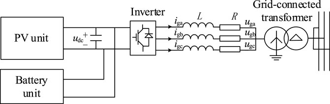
FIGURE 2. Inner structure of the PV-ES unit.
During the grid fault period, the duty cycle of the bidirectional DC-DC converter is adjusted to absorb the excess active power of the PV array to overcome the overvoltage incident on the DC-link. After the grid fault, the energy stored in the battery energy storage is injected to the grid. In this scenario, the DC-link voltage during grid faults is nearly constant and can be considered decoupled with inverter’s control.
2.2 Control strategy
The PV-ES unit is connected to the grid by the inverter which converts the direct current into the three-phase alternating current and has a strong non-linear output. Therefore, the output characteristics of the PV-ES power generation system are basically determined by the control strategy of the inverter. That means considering the impact of the control strategy on the output characteristics of PV-ES power generation system is a necessary prerequisite for the fault characteristics analysis.
Moreover, LVRT requirements have been put into effect by modern GCs. GCs in various countries explicitly have demand for the injection of reactive power during the grid fault period in order to recover grid voltage as well as assist the power system to overcome the fault incidents. As a whole, the analysis of fault characteristics of the PV-ES power generation system is mainly based on the grid-connected inverter control strategy and the LVRT control strategy.
The mathematical equation for the inverter in the two-phase synchronous rotating d-q coordinate system is shown in (1).
The inverter usually adopts the closed-loop method containing voltage outer loop and current inner loop, in which the voltage outer loop aligns the d-axis of the synchronous reference frame with the positive-sequence vector of the grid voltage (Baran and El-Markaby, 2005), called the grid voltage directional vector control technology, so that the grid voltage satisfies the following relationship:
The vector control strategy based on the grid voltage orientation can decouple the active power and reactive power output of the inverter. The relationship between output power and d-q axis currents of the inverter is shown in (3).
It can be seen from (3) that control of the output active power of the inverter can be realized through id, and the control of the output reactive power of the inverter can be realized through iq (Boutsika and Papathanassiou, 2008).
To improve the response speed of the inverter during LVRT, the voltage outer loop is disconnected, and the current inner loop is directly controlled. According to the LVRT requirements, the PV power generation system needs to guarantee the injection of reactive power during grid faults preferentially, to support the grid voltage. At the same time, in order to ensure inverter’s safety and maintain the active power balance of the power grid, the inverter should emit as much active current as possible under the maximum output current allowed.
In accordance with the principle of reactive power priority, during power grid faults, when the positive sequence of the grid voltage drops below 90%, the reference value of reactive current needs to be adaptively adjusted according to the degree of grid voltage fall. According to Chinese latest standard in 2019, the reference value expression of reactive current during LVRT is shown in (4).
Due to the grid voltage drop, the required active power of the grid needs to be reduced. Accordingly, the reference value of output active current changes with it. As a result of the limitation of the inverter’s maximum output current and reactive power priority, the actual reference value of active current after calculation is shown in (5).
2.3 Fault current analysis
The output current of the inverter is oriented to the grid voltage under normal operating conditions. However, increasing the output of reactive current during the fault period leads to the output current lagging behind the grid voltage. The relationship between the three-phase fault current outputted by the PV-ES power generation system and grid voltage (Wang et al., 2015) can be expressed as (6).
As discussed earlier, when there is a fault on the grid side, the output current of the inverter only contains three-phase symmetrical currents. Under this condition, the PV-ES power generation system can be equivalent to the voltage-controlled positive sequence current source for fault analysis. Consequently, the functional relationship between the positive sequence current
Where
To sum up, it is clear that the fault current characteristics of the PV-ES power generation system are very different from those of the traditional synchronous generator in the case of grid faults.
3 Applicability analysis of transformer differential protection
3.1 Composition of transformer differential protection
The transformer differential protection is composed of three components, including ratio braking component, second harmonic braking component and differential quick-break protection component (Perpinias et al., 2015). Schematic wiring diagram and logic diagram of transformer differential protection are shown in Figure 3.
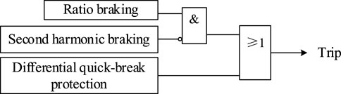
FIGURE 3. Schematic wiring diagram and logic diagram of transformer differential protection.
3.1.1 Ratio braking protection
The action equation of two-fold ratio braking protection is represented as:
Where k is usually taken as 0.5–0.8.
The operation quantity and braking quantity of transformer differential protection are defined as (Perpinias et al., 2015):
Where the positive direction of the current is flow into the transformer.
The general operating characteristic curve of ratio braking protection is shown by the solid black line in Figure 4.
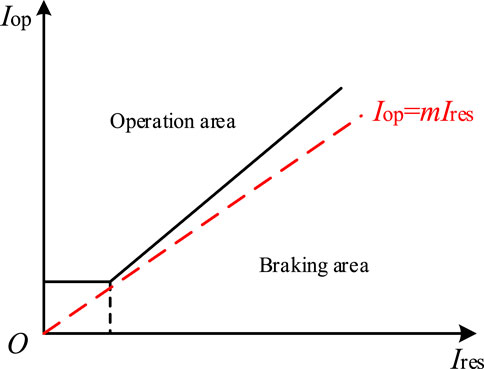
FIGURE 4. Operating characteristic curve of ratio braking protection.
For conventional two-ended power supply networks, the positive direction of current is the direction into the transformer. When three-phase short-circuit faults occur inside the protection zone of the transformer, the direction of current flowing through the CTs on both sides of the transformer is the same and amplitudes vary not greatly. So, the ratio of differential current to braking current in the event of a fault can be calculated as (10).
GCPPPs bring a phenomenon called weak-infeed, when the rated capacity of PV-ES power generation system is small (about 1/30–1/20 times or less of the short-circuit capacity of the power system). Due to this phenomenon, the contribution of PV-ES power generation system in the fault current can be ignored, and Iop/Ires is almost equal to 2, making the sensitivity of traditional transformer protection decrease. But for a large-scale GCPPP, it has non-negligible effect on the fault current. It is possible that fault current characteristics of the PV-ES power generation system further reduce m, resulting in the worse performance of transformer differential protection in this new scenario. As shown by the red dotted line in Figure 4, when m is less than k, it may not only reduce the sensitivity of transformer protection, but even make the protection refuse to operate.
3.1.2 Second harmonic braking protection
It is usually determined whether it is the transformer magnetizing inrush current by detecting the second harmonic content of differential current, so as to achieve the purpose of timely blocking differential protection to prevent maloperation. The criterion of second harmonic braking protection is shown in (11).
Where K2 is generally taken as 0.15–0.20.
To reliably block differential protection under the condition of inrush current, when difference current of any phase satisfies (11), it is judged as excitation surge current and three-phase differential protection is blocked.
3.1.3 Differential quick-break protection
When a serious fault occurs inside the transformer, the CT may be saturated and its secondary side current waveform may be distorted to contain a large number of harmonic components. This case is possible to be misjudged as excitation surge current, making differential protection do not trip or delay action, and resulting in serious damage to the transformer. So, the differential quick-break protection is configured to quickly remove the catastrophe internal fault of the transformer. If any phase current is greater than the differential quick-break current setting value, it will trip the breaker on each side.
3.2 Analysis of symmetrical faults within the transformer protection zone
First assuming that a three-phase short-circuit fault occurs on the high-voltage side of the main transformer T2, the diagram of the equivalent three-phase short-circuit fault after the fault occurs is shown in Figure 5.
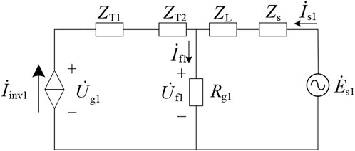
FIGURE 5. Diagram of equivalent three-phase short-circuit fault for the fault on the high-voltage side of the transformer.
According to Kirchhoff’s law of voltage and current, the following equation can be obtained in (12).
According to the definition of differential current and braking current in (9), the differential current and the braking current can be calculated with (13) for fault on the high-voltage side. What is needed to be clear is that, the calculated
What’s more, it should be noted that since the main transformer adopts the winding connection of YNd11. In the actual transformer protection calculation, the phase compensation must be carried out according to the winding connection. And for transformer of YNd11 connection, the current phase angle of the D-side of the transformer is 30° ahead of the Y-side during normal operation. Because of this current phase difference, the calculated differential current of the transformer under normal operation conditions or an external fault is not 0. Corresponding compensation methods are required to eliminate the unbalanced current caused by the different phases of the current on both sides of the transformer.
Taking phase A as an example and considering the phase adjustment as well as the ratio of transformation, the expressions of transformer differential protection after phase compensation are shown in (14).
Due to the three-phase symmetry, the phase adjustment of the Y-side current of corresponding phase is equivalent to advancing the phase of it by 30°, as shown in Figure 6.
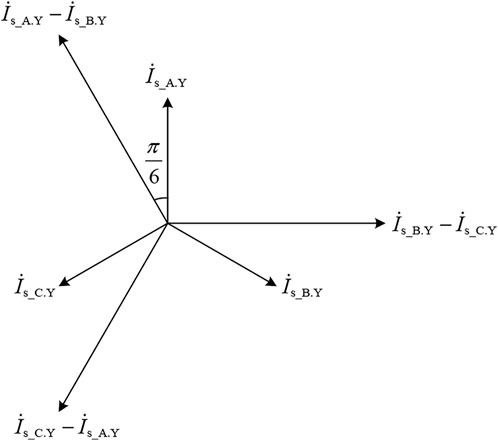
FIGURE 6. Diagram of current relationship on the both ends of the main transformer which adopts YNd11 connection.
Therefore, for three-phase short circuit faults (14) can be finalized as shown in (15).
Based on the above analysis, for three-phase short-circuit faults on the high-voltage side of the main transformer, the differential current and braking current after phase adjustment are simplistically calculated as shown in (16). Since the calculation of fault analysis adopts per unit value, the following equations do not contain ratio of transformation and only reflect the phase relationship of transformation.
Following the same line of thinking, the three-phase short-circuit fault occurs on the low-voltage side of the main transformer is analyzed too. The diagram of the equivalent three-phase short-circuit fault after the fault occurs on the low-voltage side of the main transformer is shown in Figure 7.
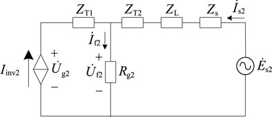
FIGURE 7. Diagram of equivalent three-phase short-circuit fault for the fault on the low-voltage side of the transformer.
According to Kirchhoff’s law of voltage and current, the following equation can be obtained:
Similarly,
The only difference is that, for three-phase short-circuit faults on the low-voltage side of the main transformer, the
4 The impact on transformer differential protection
The differential quick-break protection is mainly aimed at the saturation of CTs caused by devastating faults in the transformer. However, the focus of this paper is analyzing the influencing factors of the PV-ES power generation system access on the differential protection. Thus, this paper mainly concentrates on the performance of the second harmonic braking component and ratio braking component.
The mechanism of second harmonic generation and its impact on the transformer protection have been analyzed in very great detail in (Cohen and Callaway, 2016). That is, under grid-connected control scenarios, the drop of the grid voltage causes the inverter generating second harmonic current during transient adjustment. And this leads to more second harmonic content in grid voltage, in return affecting the output current, and forming a mechanism similar to positive feedback. Especially in the scenario where PV station is connected to a weak-grid, the short-circuit current contains a lot of second harmonic component (more than 15%), which makes the differential protection do not trip.
As for the impact of PV-ES power generation system access on ratio braking protection, detailed quantitative analysis is carried out via calculating the ratio of differential current to braking current in this paper.
Considering that three-phase short-circuit fault is the most serious fault type, it is necessary to analyze it in the first place. Besides, when the three-phase short-circuit fault occurs, the grid voltage sag is usually severe (less than 0.48). On the basis of (8), the relationship between the grid voltage and output current of the PV-ES power generation system can be obtained in (20). That’s to say, the scenario assumed in this paper is that only reactive power is output on the PV-ES side during LVRT. Therefore, the grid voltage and output current of the inverter satisfies the following relationship:
Assuming
Where Zsum = ZL + Zs, and Z’sum = ZL + Zs + ZT2.
It can be seen from (21) and (22) that the ratio of the differential current to the braking current mainly related to the rated capacity of the PV-ES power generation system (reflected by Iinv), the transition resistance Rg, the phase angle of the grid voltage φu and the length of the transmission line (namely the value of ZL).
In order to calculate the variation range of the differential current to the braking current, the relation formula of φu when the three-phase short-circuit faults occurs on the both sides of the main transformer can be analyzed first. By deriving (12) and (17), φu1 and φu2 can be denoted as shown in (23) and (24).
Where R denotes the resistance value in the impedance and X denotes the reactance value in the impedance. Rls = RL + Rs, XZ = XL + Xs, XT = XT1 + XT2 in the case of the three-phase short-circuit faults on the high-voltage side of the main transformer, and X’Z = XL + Xs + XT2, X’T = XT1 in the case of the three-phase short-circuit faults on the low-voltage side of the main transformer.
From (23) and (24), it is clear that whether the three-phase short-circuit fault occurs at the low-voltage side or high-voltage side of the main transformer, the change of φu1 and φu2 satisfy the same law. What’s more, the variation of ZL and Iinv have the same effect on Iop/Ires. Increasing ZL means the system side becoming weaker, while adding Iinv means the PV-ES system side becoming stronger. Overall, the core idea is to compare the relative contribution to fault current of the two systems on both ends. Therefore, assume the length of the transmission line is a constant. And it can be known from (23) and (24) that the change of φu is related to Ug, the rated capacity of the PV-ES power generation system as well as Rg. Nevertheless, Ug is affected by Iinv and Rg at the same time. When Rg is unchanged under the same rated capacity, the corresponding Ug can be determined uniquely. Moreover, within a certain range, Rg has a much weaker effect than Iinv on the value of Iop/Ires. Thus, the law of φu changing with the rated capacity of the PV-ES power generation system is obtained as: when Rg is certain, φu decreases as the rated capacity of the PV-ES power generation system increases.
For more accurate analysis of the changing laws, taking that the rated capacity of the PV-ES power generation system is 100MVA to 600MVA. The impedance value per unit length of the line is ZL = 0.130 + j388 Ω/km and the length is 25 km, Zs = 0.893 + j5.210 Ω, and the rated capacity of the main transformer is also 100MVA to 600MVA with short-circuit impedance of 10.5%.
For symmetrical faults on the high-voltage side, it is calculated under above setting and Rg1 is taken as 5 Ω. The corresponding variation range of φu1 is about (−120°, −60°). Then the range of Iop_H/Ires_H variation can be obtained. The changing law of Iop_H/Ires_H is shown in Figure 8. As for symmetrical faults on the low-voltage side, the variation range of φu2 for Rg2 = 0.5 Ω is about (−150°, −60°) with the same settings as the high-voltage side. In this case, the variation range of Iop_L/Ires_L is shown in Figure 9.
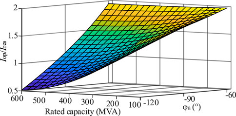
FIGURE 8. Changing law of Iop_H/Ires_H under three-phase short-circuit fault.

FIGURE 9. Changing law of Iop_L/Ires_L under three-phase short-circuit fault.
Making a comparison between Figures 8, 9, it can be seen that the values of the differential current to the braking current under non-metallic symmetrical faults on the both ends of the main transformer are all mainly below 2. What’s even more remarkable is that as the low-voltage side is closer to the PV-ES side, the fault current portion of the PV-ES side is larger. So, it has a greater impact on the performance of transformer differential protection, resulting in lower value of the differential current to the braking current.
Figures 8, 9 both show that the PV-ES power generation system access would decrease the sensitivity of transformer differential protection or even make it refuse to operate during three-phase short-circuit faults inside the protection zone of the main transformer. As mentioned above, when the value of differential current to the braking current is less than k, the differential protection has the possibility of refusing operation.
5 Simulation results
5.1 Three-phase short-circuit faults on the high-voltage side
To verify the accuracy and effectiveness of the applicability analysis of the differential protection of the main transformer, a PV-ES power generation system was established by using MATLAB/Simulink. The topology is shown in Figure 1. And the rated capacity of PV-ES power generation system is correspondingly ranging from 100 MVA to 600 MVA. The other parameters of each component in the model are presented in Table 1.
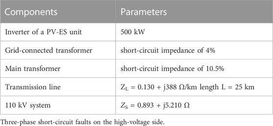
TABLE 1. PV-ES power generation system parameters.
Considering the worst-case scenario, the ratio braking coefficient k is set as 0.8. And the second harmonic braking coefficient K2 is taken as 0.15. It should be noted that the operating time of differential protection is usually considered to be after 20 m. In this case, the relationship between the rated capacity of PV-ES power generation system and the performance of differential protection is verified by simulation. Considering the symmetry of the three-phase current, the following simulation results are all based on phase A as an example.
In this case, a non-metallic three-phase short-circuit fault occurs on the high-voltage side of the transformer at t = 0.2s to t = 0.3s, and the rated capacity of PV-ES power generation system is 600MVA, transition resistance Rg1 = 5Ω. The voltage dips about 0.31 p.u., the output current of the PV-ES power generation system is increased to about 1.05 times.
Figure 10A illustrates the second harmonic content of fault current and (b) shows the variation of Iop_H/Ires_H during the non-metallic three-phase short-circuit fault on the high-voltage side of the main transformer.
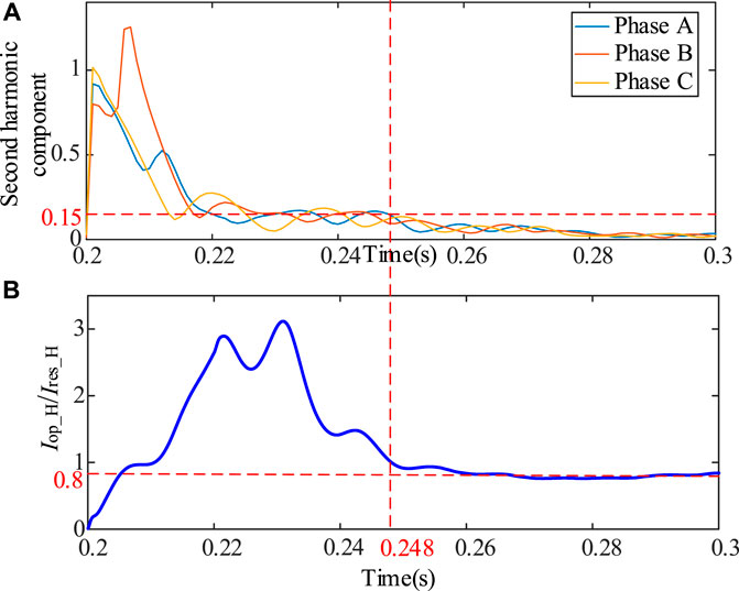
FIGURE 10. (A) Second harmonic component of differential current (B) Variation trend of Iop_H/Ires_H (high-voltage side).
In addition, Figure 10 illustrates the point that at the beginning of the fault period, the second harmonic component would block the transformer differential protection. As mentioned before, when the second harmonic content of any phase is greater than 0.15, the differential protection of the main transformer would be blocked. So, until about t = 0.248 s, the second harmonic content dropped below the setting value. At the same time, the sensitivity of the ratio braking component decreases gradually closer to the braking zone and finally below 0.8 slightly. Although at the point t = 0.248 s, Iop_H/Ires_H is a little higher than the setting value, this phenomenon suggests the non-negligible influence of the PV-ES power generation system access on the sensitivity of the transformer differential protection and implies the possibility of rejecting operation.
Figure 11 shows that φu eventually stabilizes at about −105°. As the phase angle of the grid voltage change from about 48° to −105°, Iop_H first increases and then decreases while Ires_H firstly decreases and then increases. Combining the changing trend in Figure 8, when the rated capacity of the PV-ES power generation system is 600 MVA and φu1 is below −105°, the value of Iop_H/Ires_H is below 0.8. It not only proves the correctness and effectiveness of (21) and (23), but also indicates that the transformer differential protection has a risk of not tripping in this case.
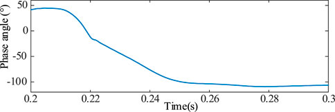
FIGURE 11. The change of φu1.
It can be seen in this case that the impact of PV-ES power generation system access on the main transformer current differential protection is the extension of protection time and reduction of the protection sensitivity, or even rejecting operation.
Table 2 supplements the steady-state values of Iop_H/Ires_H in the case of three-phase short-circuit faults with different Rg1 on the high-voltage side when rated capacity of the PV-ES power generation system is 100MVA to 600MVA.
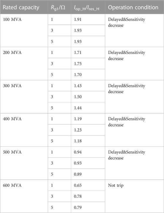
TABLE 2. Differential protection operation condition of the main transformer under symmetrical faults on high-voltage side.
5.2 Three-phase short-circuit faults on the low-voltage side
This case shows that a three-phase short-circuit fault occurs on the low-voltage side of the main transformer at t = 0.2 s to t = 0.3 s, the rated capacity of PV-ES power generation system is still 600 MVA, transition resistance Rg2 = 0.5 Ω. The voltage dips about 0.22 p.u., the output current of the PV-ES power generation system is increased to about 1.05 times.
Figure 12A illustrates the second harmonic content of fault current and (b) shows the variation of Iop_L/Ires_L during the non-metallic three-phase short-circuit fault on the low-voltage side of the main transformer. It can be seen from Figure 12A that, as the voltage sag is smaller than the last case, the second harmonic content is less, and the positive feedback effect is weaker.
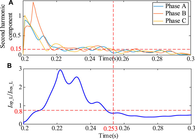
FIGURE 12. (A) Second harmonic component of differential current (B) Variation trend of Iop_L/Ires_L (low-voltage side).
As analyzed before, with the phase angle of the grid voltage change from about 48° to −128°, Iop_L first increases and then decreases while Ires_L firstly decreases and then increases. Thus, Iop_L/Ires_L shows a sharp decrease in Figure 12 during the transient process.
Besides, after the second harmonic braking, the value of Iop_L/Ires_L has reached steady state and is less than 0.8. This phenomenon also represents that the differential protection of the main transformer would first be blocked by the second harmonic braking component and then as the differential current decreases and the braking current increases, it would refuse to operate.
Figure 13 shows that φu2 eventually stabilizes at around −128°. It can refer to Figure 9 that when rated capacity of the PV-ES power generation system is 600 MVA, Rg2 = 0.5 Ω and φu2 is −128°, the value of Iop_L/Ires_L is about 0.4, which again proves the correctness and effectiveness of (22) and (24).
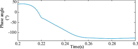
FIGURE 13. The change of φu2.
It can be seen that the impact of PV-ES power generation system access on the main transformer current differential protection is not only the extension of protection time and reduction of the protection sensitivity, but also rejecting operation.
Table 3 supplements the steady-state values of Iop_L/Ires_L in the case of three-phase short-circuit faults with different Rg2 on the low-voltage side when rated capacity of the PV-ES power generation system is 100 MVA to 600 MVA.
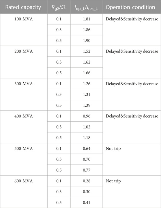
TABLE 3. Differential protection operation condition of the main transformer under symmetrical faults on low-voltage side.
Table 2 and Table 3 show the contrast of different fault location at the same rated capacity, which indicates that the fault on the low-voltage side has a greater impact on the performance of transformer differential protection. The reason is that its location is closer to the PV-ES power generation system. In addition, it also indicates that on the same fault location, as the rated capacity of the PV-ES power generation system increases, the values of differential current to braking current all gradually decrease. These simulation results are consistent with the trends analyzed in Section 4.
5.3 Other influencing factors
In order to further analyze the operation performance of transformer differential protection, three-phase short-circuit faults were set at both sides of main transformer under different length of the transmission line.
What can be clearly seen in Figure 14 are the values of differential current to braking current all gradually decrease with length of the transmission line increases. Just as mentioned above, extending the length of the transmission line has the same effect as increasing the rated capacity of the PV-ES power generation system (namely weaken the 110 kV system). So, it means that the sensitivity of the transformer differential protection decreases as the length of the transmission line increases.
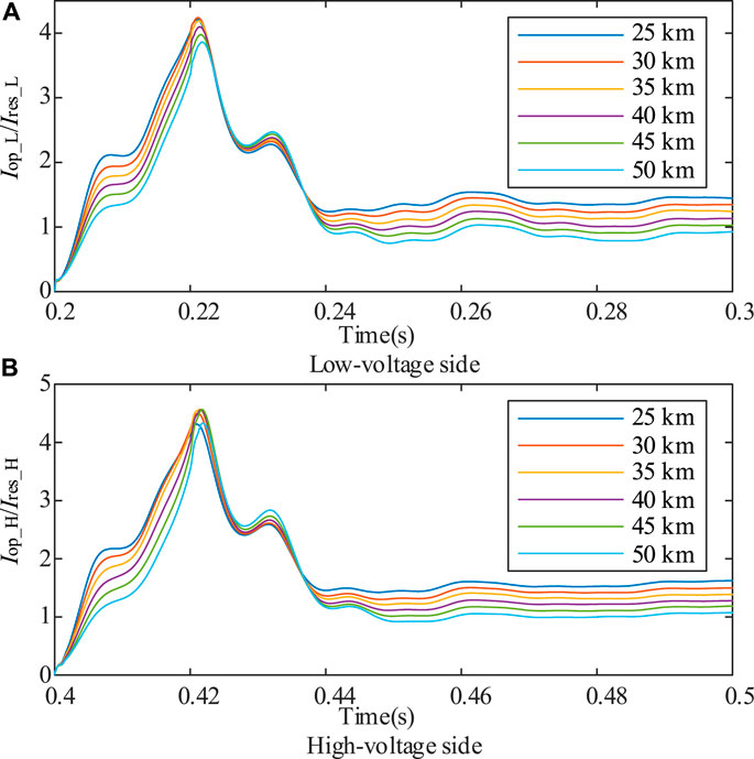
FIGURE 14. Comparison of variation trend of Iop_L/Ires_L and Iop_H/Ires_H with the different lengths of the transmission line. The shows the influence of the length of the transmission line on the operation performance of the transformer differential protection Figure 14.
Overall, these cases support the view: considering the second harmonic braking component and the ratio braking component, the influence of the PV-ES power generation system access on the transformer differential protection is prolonging the operation time of differential protection, reducing the sensitivity of it or even making it reject operation.
6 Conclusion
This paper deduces the ratio of differential current over braking current for three-phase short-circuit faults at both sides of the main transformer, analyzes the impact of grid-connected PV-ES power generation system on the differential protection of the main transformer in detail, and combines operation of the second harmonic braking component in simulation results to comprehensively present the applicability analysis of traditional transformer differential protection. The following conclusions are finally reached.
The factors that affect the differential protection operation are the scale of PV-ES power generation system, fault severity, the length of transmission line and so on. Among these factors, the most important factor is the scale of PV-ES power generation system. With the scale of the PV-ES power generation system becoming larger, the contribution of the PV-ES power generation system to fault current cannot be ignored. As a result, the large-scale grid-connected PV-ES power generation system would make the sensitivity of transformer differential protection decrease significantly, or even refuse to trip. Especially when the faults are on the low-voltage side of the main transformer, the transformer differential protection is more likely to refuse operation. Which will cause serious damage to the main transformer.
As an indispensable power equipment in the transmission system, the safe operation of the main transformer is very important for the transmission system. In the scenario of clean energy access, the study on the adaptability of the differential protection of the main transformer can provide a necessary theoretical basis for improving the principle of differential protection and avoid major accidents in practical projects. To sum up, these findings of this paper contribute in providing a basis for further progress in transformer differential protection.
Data availability statement
The original contributions presented in the study are included in the article/Supplementary Material, further inquiries can be directed to the corresponding author.
Author contributions
GY: Conceptualization, Methodology, Validation, Writing-Review and Editing. JZ: Conceptualization, Methodology, Validation, Writing-Review and Editing. HZ: Resources, Investigation. CW: Resources, Supervision. YZ: Data curation, Methodology, Software, Writing-Original draft preparation. XC: Supervision.
Funding
This work is supported by Science and Technology Project of State Grid Corporation of China (Project No.5100-202155028A-0-0-00).
Conflict of interest
JZ was employed by the company State Grid Corporation of China.
The remaining authors declare that the research was conducted in the absence of any commercial or financial relationships that could be construed as a potential conflict of interest.
The authors declare that this study received funding from State Grid Corporation of China. The funder had the following involvement in the study: the study design, data collection.
Publisher’s note
All claims expressed in this article are solely those of the authors and do not necessarily represent those of their affiliated organizations, or those of the publisher, the editors and the reviewers. Any product that may be evaluated in this article, or claim that may be made by its manufacturer, is not guaranteed or endorsed by the publisher.
Abbreviations
CT, current transformer; PV, photovoltaic; PV-ES, photovoltaic-energy storage; LVRT, low voltage ride-through; IIDG, inverter-interfaced distributed generator; GCPPP, grid-connected photovoltaic power plant; GC, grid code; ESS, energy storage system; SCR, short-circuit capacity ratio; PCC, point of common coupling.
References
Al-Hilfi, H. A. H., Abu-Siada, A., and Shahnia, F. (2021). Estimating generated power of photovoltaic systems during cloudy days using gene expression programming. IEEE J. Photovoltaics 11 (1), 185–194. doi:10.1109/JPHOTOV.2020.3029217
Al-Shetwi, A. Q., Sujod, M. Z., Blaabjerg, F., and Yang, Y. (2019). Fault ride-through control of grid-connected photovoltaic power plants: A review. Sol. Energy 180, 340–350. doi:10.1016/j.solener.2019.01.032
Alepuz, S., Busquets-Monge, S., Bordonau, J., Martinez-Velasco, J. A., Silva, C. A., Pontt, J., et al. (2009). Control strategies based on symmetrical components for grid-connected converters under voltage dips. IEEE Trans. Ind. Electron. 56, 2162–2173. doi:10.1109/TIE.2009.2017102
Almeida, P. M., Monteiro, K. M., Barbosa, P. G., Duarte, J. L., and Ribeiro, P. F. (2016). Improvement of PV grid-tied inverters operation under asymmetrical fault conditions. Sol. Energy 133, 363–371. doi:10.1016/j.solener.2016.04.015
Alsafasfeh, Q., Saraereh, O., Khan, I., and Kim, S. (2019). LS-solar-PV system impact on line protection. Electronics 8, 226. doi:10.3390/electronics8020226
Baran, M. E., and El-Markaby, I. (2005). Fault analysis on distribution feeders with distributed generators. IEEE Trans. Power Syst. 20, 1757–1764. doi:10.1109/TPWRS.2005.857940
Boutsika, T. N., and Papathanassiou, S. A. (2008). Short-circuit calculations in networks with distributed generation. Electr. Power Syst. Res. 78, 1181–1191. doi:10.1016/j.epsr.2007.10.003
Cohen, M. A., and Callaway, D. S. (2016). Effects of distributed PV generation on California’s distribution system, Part 1: Engineering simulations. Sol. Energy 128, 126–138. doi:10.1016/j.solener.2016.01.002
Das, U. K., Tey, K. S., Seyedmahmoudian, M., Mekhilef, S., Idris, M. Y. I., Van Deventer, W., et al. (2018). Forecasting of photovoltaic power generation and model optimization: A review. Renew. Sustain. Energy Rev. 81, 912–928. doi:10.1016/j.rser.2017.08.017
Gao, H., Li, J., and Xu, B. (2017). Principle and implementation of current differential protection in distribution networks with high penetration of DGs. IEEE Trans. Power Deliv. 32, 565–574. doi:10.1109/tpwrd.2016.2628777
Haidar, A. M. A., Ramli, F., and Helwig, A. “Analysis of grid-connected solar PV system operation based on energy router concept,” in Proceedings of the 2022 7th IEEE Workshop on the Electronic Grid (eGRID), Auckland, New Zealand, November. 2022. doi:10.1109/eGRID57376.2022.9990021
Hooshyar, A., Azzouz, M. A., and El-Saadany, E. F. (2015). Distance protection of lines emanating from full-scale converter-interfaced renewable energy power plants—part I: Problem statement. IEEE Trans. Power Deliv. 30, 1770–1780. doi:10.1109/tpwrd.2014.2369479
Jia, K., Gu, C., Xuan, Z., Li, L., and Lin, Y. (2018). Fault characteristics analysis and line protection design within a large-scale photovoltaic power plant. IEEE Trans. Smart Grid. 9, 4099–4108. doi:10.1109/tsg.2017.2648879
Jin, E., Li, S., and Xia, G. (2020). “Analysis of impact of photovoltaic power generation system on transformer differential protection,” in Proceedings of the 2020 IEEE International Conference on High Voltage Engineering and Application (ICHVE), Beijing, China, September 2020 (IEEE). doi:10.1109/ICHVE49031.2020.9279757
Liang, Y., Li, W., and Xu, G. (2020). Performance problem of current differential protection of lines emanating from photovoltaic power plants. Sustainability 12, 1436. doi:10.3390/su12041436
Liu, S., Bi, T., and Liu, Y. (2017). Theoretical analysis on the short-circuit current of inverter-interfaced renewable energy generators with fault-ride-through capability. Sustainability 10, 44. doi:10.3390/su10010044
Neumann, T., and Erlich, I. (2012). Short circuit current contribution of a photovoltaic power plant. IFAC Proc. Vol. 45, 343–348. doi:10.3182/20120902-4-fr-2032.00061
Nimpitiwan, N., Heydt, G. T., Ayyanar, R., and Suryanarayanan, S. (2007). Fault current contribution from synchronous machine and inverter based distributed generators. IEEE Trans. Power Deliv. 22, 634–641. doi:10.1109/TPWRD.2006.881440
Perpinias, I. I., Papanikolaou, N. P., and Tatakis, E. C. (2015). Fault ride through concept in low voltage distributed photovoltaic generators for various dispersion and penetration scenarios. Sustain. Energy Technol. Assessments 12, 15–25. doi:10.1016/j.seta.2015.08.004
Wang, M., Yu, J., Zheng, T., Chen, Z., Wen, F., Luo, L., et al. (2020). Mechanism of second harmonic generation of photovoltaic grid-connected system faults and its impact on transformer protection. Energy Rep. 6, 1619–1627. doi:10.1016/j.egyr.2020.12.027
Wang, Q., Zhou, N., and Ye, L. (2015). Fault analysis for distribution networks with current-controlled three-phase inverter-interfaced distributed generators. IEEE Trans. Power Deliv. 30, 1532–1542. doi:10.1109/TPWRD.2015.2407883
Nomenclature
ud, uq d axis component and q axis component of the inverter output voltage
ugd, ugq d axis component and q axis component of the grid voltage
P, Q Output active and reactive power of the PV-ES power generation system
IN Rated output current of inverter
Id, Iq Amplitude of the d axis and q axis component current of PV-ES power generation system
Iop, Ires Differential current and braking current (Subscripts “_H” and “_L” donate the fault on the high-voltage side and low-voltage side)
k Ratio braking coefficient
m Ratio of differential current to braking current
Iset.min, Ires.min Setting value of minimum operating current and braking current
Rg1, Rg2 Transition resistance at the fault point for the fault on the high-voltage side and low-voltage side
n Ratio of transformation
id, iq d axis component and q axis component of inverter current
id*, iq* d axis component and q axis component of inverter reference current
R, L Filter resistance and inductance
ω1 Synchronous angular velocity
φu, φi Phase angle of the grid voltage and the current of PV-ES power generation system (Subscripts “1” and “2” donate the fault on the high-voltage side and low-voltage side)
φiu Angle of current of PV-ES power generation system lagging behind the grid voltage
K2 Second harmonic braking coefficient
Id1, Id2 Amplitude of the fundamental current and second harmonic current of the differential current
Zs, ZL, ZT1, ZT2 Equivalent impedance of the 110 kV system, transmission line, parallel grid-connected transformers T11-T1n and main transformer T2
Keywords: energy storage, photovoltaic (PV), low voltage ride-through, grid-connected PV, transformer protection, differential protection
Citation: Yang G, Zhang J, Zhang H, Wang C, Zhu Y and Chen X (2023) Impact of large-scale photovoltaic-energy storage power generation system access on differential protection of main transformer under symmetrical faults. Front. Energy Res. 11:1115110. doi: 10.3389/fenrg.2023.1115110
Received: 03 December 2022; Accepted: 11 January 2023;
Published: 26 January 2023.
Edited by:
Enrico Pons, Polytechnic University of Turin, ItalyReviewed by:
Narottam Das, Central Queensland University, AustraliaSrete Nikolovski, Josip Juraj Strossmayer University of Osijek, Croatia
Copyright © 2023 Yang, Zhang, Zhang, Wang, Zhu and Chen. This is an open-access article distributed under the terms of the Creative Commons Attribution License (CC BY). The use, distribution or reproduction in other forums is permitted, provided the original author(s) and the copyright owner(s) are credited and that the original publication in this journal is cited, in accordance with accepted academic practice. No use, distribution or reproduction is permitted which does not comply with these terms.
*Correspondence: Yujia Zhu, amFtaWVfMjE1eWp6QHRqdS5lZHUuY24=