 Richard Skifton
- Idaho National Laboratory, Measurement Science Laboratory, Idaho Falls, ID, United States
This article presents an instability model for the high-temperature irradiation-resistant thermocouple (HTIR-TC). Here the term instability defines the superposition of both drift and inhomogeneity of TC thermoelements occurring simultaneously. The HTIR-TC is an advanced thermocouple (TC) that uses the refractory metals niobium and molybdenum as sensing thermoelements for generating electromotive force (EMF) in a field of neutrons and at temperatures upward of 1,600°C. In the Advanced Gas Reactor (AGR) 5/6/7 tests conducted at Idaho National Laboratory’s Advanced Test Reactor (ATR), the HTIR-TCs showed low to moderate instability throughout the life of the test. The instability model reveals that HTIR-TCs can, when the operating temperature of the reactor fuel is normal, maintain performance throughout an 18-month refueling cycle typical of nuclear power plants, reflecting an instability of less than ±1%. The HTIR-TC is also qualified for incorporation into a test fixture during the testing of new fuels.
1 Introduction
Extensive research and development have been performed on Idaho National Laboratory’s high-temperature irradiation-resistant thermocouple (HTIR-TC) design, extending as far back as 1988 (Wilkins, 1988). The initial research by Wilkins showed that, when it came to selecting the thermocouple (TC) thermoelements, molybdenum (Mo) and niobium (Nb) were the top candidates in terms of resisting TC decalibration (i.e., drift) during any long-term tests in which they were placed near or inside nuclear fuel. Since that time, every aspect of the HTIR-TC has been closely studied, including the thermoelements (Wilkins, 1988; Wilkins and Schooley, 1992; Rempe and Wilkins, 2005a; Rempe and Wilkins, 2005b; Wilkins and Evans, 2005; Rempe et al., 2006a; Rempe et al., 2006b) and associated dopants, formation of TC junctions, insulation (Daw et al., 2007), sheath (Rempe et al., 2007), long-term effects of exposure to high temperatures (Rempe et al., 2008; Daw, 2009), extension wiring (Daw et al., 2008), manufacturing and heat treatment processes (Daw et al., 2008), calibration and associated electromotive force (EMF) (Skifton et al., 2018), out-of-pile performance (Riley et al., 2019; Skifton, 2019; Skifton et al., 2019; Riley et al., 2020), transmutation affects (Skifton, 2021a), fuels and reactor temperatures (Jensen, 2007; Palmer, 2015; Palmer et al., 2019a; Palmer et al., 2019b; Palmer et al., 2021), and improved optimizations (Skifton, 2021c; Skifton et al., 2021).
The HTIR-TC consists of two thermoelements (i.e., one being Mo and the other Nb), an insulator (either alumina or magnesia), and an outer sheath of pure Nb. A successful qualification test was performed for the HTIR-TC through the Nuclear Energy Enabling Technologies Advanced Sensors and Instrumentation program (Dayal and Jensen, 2019; Skifton, 2021b). For this qualification test, the HTIR-TC underwent in-reactor testing for over 12 months in the Advanced Test Reactor (ATR)’s high-neutron-flux, high-temperature environment, as part of the Advanced Gas Reactor (AGR) 5/6/7 fuel test (Palmer et al., 2014). In this test, several HTIR-TCs were placed at various locations around the fuel fixtures to evaluate the performance of new advanced fuel designs for the AGR program.
As all TC types show some form of instability with use, quantifying the total amount experienced by a TC within neutron flux fields and high-temperature tests are the main objective of the present work. The instability of a TC signal derives from the inhomogeneity (White, 1906; Kim et al., 2009; Sloneker, 2009) and eventual drift of the nuclear TCs during the unique circumstance of long-term exposure to neutron bombardment and/or excessive high temperatures. Excessive high temperature leads to solid-state diffusion of atoms into the thermoelements. Strictly in nuclear applications, exposure of the TC thermoelements to the neutron field eventually leads to a significant amount of transmutation. Both phenomena are represented in the developed instability model. The developed instability model for HTIR-TCs can be directly applied to other nuclear experiments, and even to different TC types, builds, and applications. The drift should be small enough that the temperature measurements can be accepted as reasonable, and that the TC is shown to survive for extended periods of time (i.e., a nuclear power plant’s 18-month refueling cycle). It is important to understand the basic principles of this instability model, as it is applicable to all TC types employed in measuring reactor core temperatures, even when the temperatures are low.
2 Experimental setup
Comprised of five capsules, the AGR-5/6/7 fuel test fixture was inserted into the ATR’s northeast flux trap—with an inside diameter of 13.34 cm (5.25 in). Each capsule was ∼7 cm (2.75 in) in diameter and with all five capsules welded together gave an overall test train length of 1.22 m (Test train orientation and further details on TC placement can be seen in Figure 1 and are found in greater detail in (Palmer et al., 2014; Hawkes, 2019).) The capsules were positioned in ascending order, with Capsule 1 being located at the bottom of the active core and Capsule 5 at the top. The capsules contained varying amounts of test fuel that, in interacting with the neutron flux, produced varying degrees of temperature. These temperatures were then measured by the TCs, thus generating the required test data on fuel—and in turn, TC—performance.
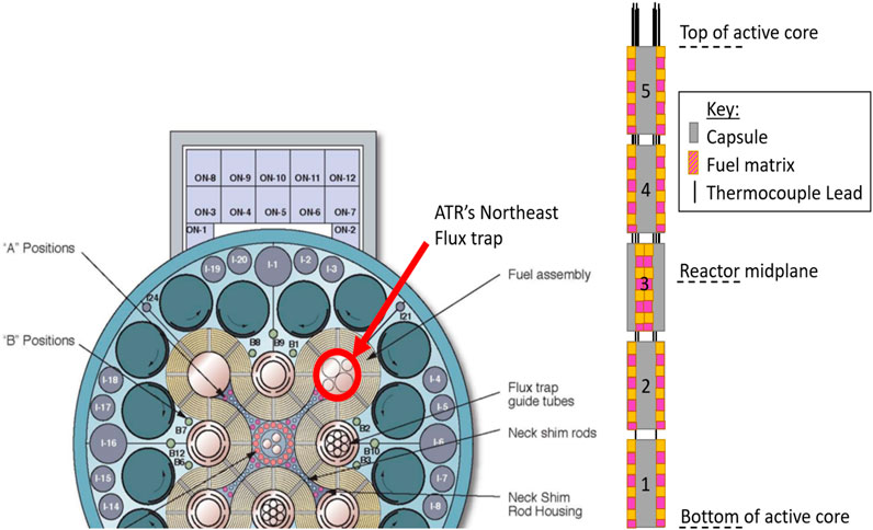
FIGURE 1. ATR layout of northeast flux trap utilized in the AGR 5/6/7 experiment and elevation of capsules within active core (not to scale).
ATR’s overarching thermal neutron flux follows a symmetrical, cosine-squared profile, with a maximum, perturbed, thermal, neutron flux value of ∼2.8 × 10¹⁴ n/cm2s existing at the reactor height midplane (estimated from (ATR National Scientific User Facility, 2009)), along with a fast (i.e., E > 1 MeV) neutron flux value of approximately 2.25 × 10¹⁴ n/cm2s (ATR National Scientific User Facility, 2009). The neutron flux then follows the cosine-squared profile outwards from centerline decaying rapidly to the top and bottom of the reactor height. The temperature range of each capsule varied according to total irradiation and capsule fuel placement. Capsule 3 was expected to show the highest temperatures—mainly as a result of being placed at the reactor height midplane.
Of the five capsules, only Capsules 1 and 3 contained HTIR-TCs for measuring the experimental temperatures. However, the lead wires for each TC must exit the reactor core by passing upward through designated channels inside capsule located above. This means, for example, that the HTIR-TCs positioned to measure temperatures in Capsule 1 must pass through the higher neutron flux regions of the reactor core. Thus, although the HTIR-TCs in Capsule 1 measure a lower temperature, the TC cable drift caused by thermal- and fast-neutron-flux-induced changes (discussed in Section 3.3) would be similar for all the TCs placed in Capsules 1 and 3.
The test fixture also had provision to pass a small, adjustable He-Ne mixture gas flow around the inside of the capsules to maintain a constant temperature and minimize the effect of power fluctuations on the TC temperature readings (Scates et al., 2020). The gas flow was kept at a minimal value and did not remove heat by convection; instead, it merely provided a high thermal conduction path leading directly to the cooler high-water flow of the reactor coolant outside the capsule.
3 AGR 5/6/7 temperature data
The following data were collected from the AGR 5/6/7 test conducted at Idaho National Laboratory’s ATR (ATR National Scientific User Facility, 2009). With respect to reactor core height, Capsule 1 and Capsule 3 in the AGR-5/6/7 fuel test were the bottommost capsule and the midplane capsule, respectively. The HTIR-TCs were positioned in the hottest region of each capsule—for an average measured temperature of about 1,300°C for Capsule 1, and 1,500°C for Capsule 3.
HTIR-TCs 1-12, 1-13, 1-14, and 1-15 each measured the hottest regions of Capsule 1 by being positioned within the inner circle of temperature sensors closest to the fuel. The data were collected over approximately 425 calendar days, covering the operating lifetimes of all Capsule 1 HTIR-TCs in the AGR-5/6/7 test fixture. Figure 2 shows the daily temperature averages of each HTIR-TCs’ operational lifetimes, in ATR equivalent full-power days (EFPDs), as calculated by noting the length of time each TC was operational, in conjunction with how long the ATR was at full power. The operational lifetimes of HTIR-TCs 1-12, 1-13, 1-14, and 1-15 were 120, 87, 161, and 120 EFPDs, respectively. The EFPD range that each individual thermocouple experienced stems from random effects that the heat treatment, calibration, and physical handling of each TC underwent prior to installment into the AGR 5/6/7 capsules. The main failure mechanism was the stochastic process of reactor shutdown and restart that causes a sharp temperature gradient on the thermocouples leading to a guillotine total failure of the sensor.
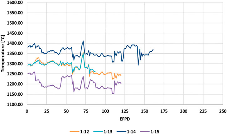
FIGURE 2. Temperatures indicated by HTIR-TCs 1-12, 1-13, 1-14, and 1-15 in Capsule 1 of the AGR-5/6/7 fuel test.
Figure 3 shows the daily averaged temperature data collected at full reactor power from all three Capsule 3 HTIR-TCs throughout their operational lifetimes. The operational lifetimes of HTIR-TCs 3-5, 3-12, and 3-14 were 125, 166, and 164 EFPDs, respectively.
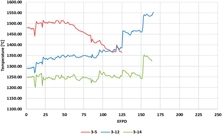
FIGURE 3. Temperature indicated by HTIR-TCs 3-5, 3-12, and 3-14 in Capsule 3 of the AGR-5/6/7 fuel test.
The highest temperature reached during the AGR 5/6/7 campaign was ∼1,550°C, as measured by HTIR-TC 3-12 toward the end of irradiation period. This is believed to be the highest temperature ever withstood and measured by a TC within the reactor core (i.e., in-pile TC). Though the temperature in the experimental test fixture was lower than the HTIR-TC’s specified maximum temperature of 1,600°C, the preliminary, out-of-pile test data suggest that the HTIR-TCs can indeed accurately measure temperatures all the way up to 1,600°C. However, the instability that would occur at that high a temperature is uncertain and would have to be analyzed and/or measured.
Capsule 1 contained four operating HTIR-TCs around the inside perimeter of the test fuel. These measured slightly lower temperatures than those in Capsule 3. A comparison between these HTIR-TC temperature readings and the temperatures predicted by the thermal model is given in (Pham et al., 2020).
Placed in the center of Capsule 3’s hot zone, HTIR-TC 3-5 measured temperatures of around 1,453°C for the first few weeks of operation at full reactor power. The theoretically calculated temperature at that location was 1,436°C. The difference is around 17°C (or ∼1.2%) lower than the measured temperature.
Capsule 3 contained three type-N TCs in the same lower temperature zone as HTIR-TC 3-14, and all four of these TCs gave similar temperature measurements, further evidencing the HTIR-TC’s accuracy at lower temperatures (see Section 3.2.2 for further details). For comparison purposes, the type-N TCs are included in this discussion, though they can only measure temperatures of up to 1,260°C (or 1,290°C over a very short period) before nearing their melting point restrictions. On the other hand, as already stated, the HTIR-TCs can measure temperatures of up to 1,600°C.
3.1 HTIR-TC temperature range and accuracy
The HTIR-TC temperature range was established through several years of out-of-pile testing (Wilkins, 1988; Wilkins and Schooley, 1992; Rempe and Wilkins, 2005a; Rempe and Wilkins, 2005b; Wilkins and Evans, 2005; Rempe et al., 2006a; Rempe et al., 2006b; Daw et al., 2007; Rempe et al., 2007; Rempe et al., 2008; Daw, 2009). Exhaustive preliminary out-of-pile testing is indicative of in-pile nuclear testing, as both are expensive and time consuming. In the in-pile test design, different TC types were applied to various temperature ranges to help validate neighboring measurements. The HTIR-TCs inside the AGR 5/6/7 test rig were identically constructed from a consistent batch of individual materials. From all HTIR-TCs, ten (a representative sample size) were individually calibrated, and their measured accuracy in the 0°C–1,600°C range was either ±1°C or ±0.4% of the temperature reading, whichever was greater (Skifton et al., 2018). This represents the as-manufactured accuracy of all the AGR 5/6/7 HTIR-TCs and is not to be confused with calibration instability in a neutron flux environment, discussed in below in Section 3.3.
The AGR-5/6/7 test was not configured to measure the true in situ accuracy of the HTIR-TCs, as it lacked a calibrated reference TC that could be dropped into the capsule(s). However, a theoretical estimate of each capsule temperature was attained using the ABAQUS finite element model (Pham, 2021). Over the first 14 days of operation, a temperature deviation of less than ±5% between the ABAQUS model and the temperature measured directly by the HTIR-TCs was observed. The constancy of the temperature measurements made early in life—prior to any appreciable drift—by the HTIR-TCs in both Capsules 1 and 3 gave indication of what the baseline temperature measurements were. A summary of comparisons between TC measurements and calculations can be seen in Table 1.
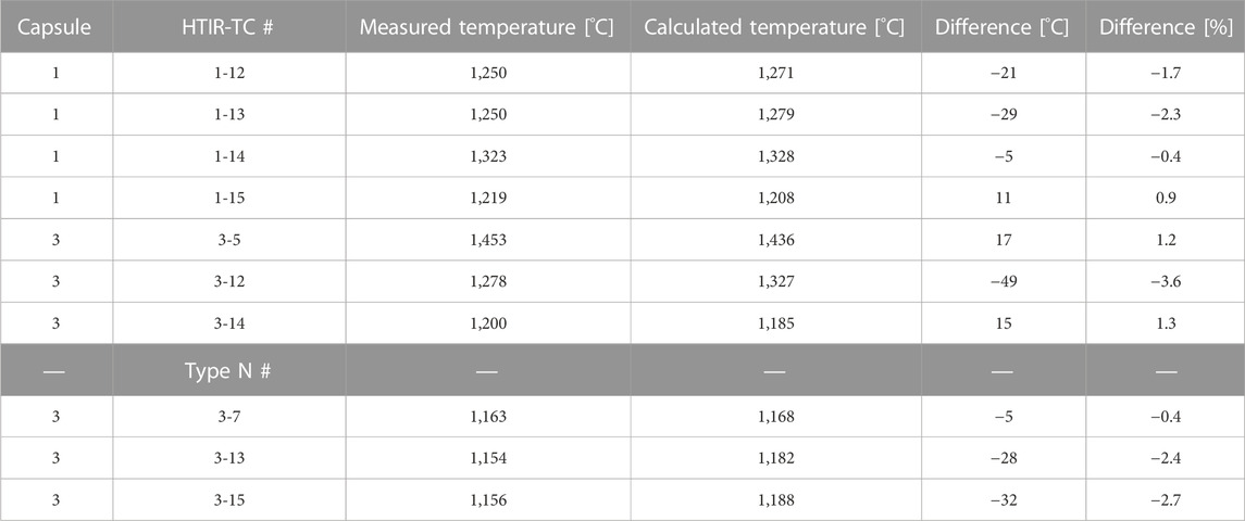
TABLE 1. HTIR-TC measured vs. calculated temperature results.
3.2 AGR 5/6/7 drift and inhomogeneity results
3.2.1 Capsule 1 HTIR-TC drift and inhomogeneity trends
According to the data in Figure 2, the four HITR-TCs in Capsule 1 apparently experienced a small downward drift of 3%–4% after residing in ATR for 150 EFPDs; however, this could not be well quantified over the noise in the data, which resulted from experimental error. The capsule temperatures fluctuated around approximately ±2% and appeared to be synchronized, indicating it was caused by changes in the ambient temperature, not in the TC response. These fluctuations can be sourced to a culmination of phenomenon like overall gas flow, vibrations in the TC junction location, reactor power fluctuations, among other secondary sources like thermal expansion and contraction of the fuel matrix. The sharp spatial temperature gradient of each capsule grossly exaggerates each phenomenon, as well. Figure 4 reveals this trend more clearly, as a function of time, with the TC daily averaged temperature measurements being normalized to their initial value, T0. A collocated type-N TC is also shown for comparison purposes. These data reveal the HTIR-TCs in Capsule 1 to have performed as expected. Operating for that length of time at a temperature of 1,280°C generally produced a downward drift of −3.5%.
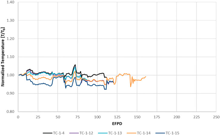
FIGURE 4. Temperature measurements from the HTIR-TCs and type-N TC in AGR-5/6/7 Capsule 1, normalized by the initial in situ temperature measurement, TINT. The HTIR-TCs are in color, and the type-N TC (1-4) is in black.
3.2.2 Capsule 3 HTIR-TC drift and inhomogeneity trends
The data in Figure 3 show different temperature measurement trends for the three HTIR-TCs in Capsule 3 (i.e., 3-5, 3-12, and 3-14). Figure 5 more clearly shows these trends as a function of time, with the TC daily averaged temperature measurements being normalized to T0. HTIR-TC 3-14 showed no change in trend, either up or down, whereas 3-12 showed an upward trend. An examination of type-N TCs in a temperature location similar to that of 3-12 (i.e., same capsule but a lower temperature region) also revealed the same upward trend. HTIR-TC 3-5, on the other hand, showed a significant downward trend.
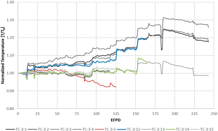
FIGURE 5. Temperature measurements from the HTIR-TCs and type-N TCs in Capsule 3 of AGR-5/6/7, normalized by the initial in situ temperature measurement, TINT. The HTIR-TCs are in color, and the type-N TCs are in grayscale.
These data indicate that the noise in the measured temperatures for all the TCs is synchronized in their local regions, meaning they do not reflect true TC drift but rather a trend indicative of changes in the ambient temperature environment.
Figure 5 reveals the three types of measured temperature trends exhibited by the TCs in Capsule 3:
1. The first trend is the relatively constant temperatures exhibited by HTIR-TC 3-14 and type-N TCs 3-2, 3-13, and 3-15 at up to 150 EFPDs. In particular, note that type-N TC 3-13 was the “control” TC for the entirety of the experiment, meaning that the reactor power and gas flow mixture was adjusted based on its temperature readings. After 150 EFPDs, all the TCs noted a synchronized temperature increase, indicating a sudden increase in the surrounding temperature.
2. The second trend is that a cluster of TCs (specifically HTIR-TC 3-12 and type-N TCs 3-1, 3-3, and 3-4) all showed a gradual increase in temperature measurement readings with time once the specified lifetime of the TCs was reached, and this increase lasted all the way until shortly after the 175 EFPD mark. There is no physical reason why the sensitivity of this entire type-N/HTIR-TC group would synchronously increase. This rise in measured temperatures was not due to any TC sensitivity change (i.e., drift), but rather an actual temperature increase in this region of Capsule 3. It is also likely that this ambient temperature increase cancelled out the expected downward drift. The reason for this increase is not well understood, but likely relates to the difficulty of maintaining a constant temperature for the Capsule 3 design and is under further review. One reason why the measurements from type-N TCs 3-1, 3-3, and 3-4 trended upward is because they were in the outer of the capsule’s two graphite layers. As the fuel reduces over time, less heat flux moves from the fuel to the capsule wall, which is cooled by water. To maintain a constant temperature in the fuel, a larger temperature increase begins to manifest between the wall and the inner layer of graphite. Thus, these three TCs can be expected to climb in temperature as the fuel decays. A second reason for the temperature rise is that the concentration of He and Ne gases flowing through the capsule was altered so as to maintain a constant temperature—potentially affecting an increase in the temperatures read by the TCs. Thirdly, examination of the experimental test data showed that the TC used to control the test capsule temperature (i.e., TC-3-13) was losing sensitivity. This would cause an increase in Capsule 3’s ambient temperature.
3. The third trend pertains to the measurements from HTIR-TC 3-5. Being the only TC located in the center of Capsule 3, HTIR-TC 3-5 had no other similarly located TCs against which it could be compared. HTIR-TC 3-5 showed a relatively constant reading at up to approximately 75 EFPDs, at which point its temperature readings started to decrease, leading to a 125°C change (8.7%) at 125 EFPDs. If the capsule was increasing in temperature, as is suggested by the data from HTIR-TC 3-12 and the similarly located type-N TCs, this downward drift could have exceeded 10%. It is unlikely that this large downward drift was due to a large temperature decrease at this location. It is also unlikely to have been caused by fast neutron damage or thermal neutron transmutations, since the cables of all the other HTIR-TCs experienced similar thermal and fast neutron fluxes without registering the same large downward drift. It is more likely that this drift was due to a real decrease in TC sensitivity, caused by prolonged residence time at high temperature (∼1,500°C). It is possible that, although HTIR-TC 3-5 was heat treated to 1,450°C for several hours during manufacturing, it needed to be instead heat treated to a higher temperature and for a longer time to become stabilized for long-term operation at higher temperatures (i.e., 1,500°C–1,600°C).
3.3 HTIR-TC instability analysis
The following general factors apply to our understanding of the drift that results when HTIR-TCs in the ATR test fixture are exposed to neutron fluxes and high temperatures:
1. Neutron-fluence-induced TC drift is primarily due to neutron-fluence-induced transmutations and neutron bombardment effects in the thermoelement cables (Scervini et al., 2013). These effects lead to Seebeck coefficient changes as a function of residence time in the reactor. The TC measurements are affected only in regions where temperature gradients exist. Thus, the instability in the Capsule 1 TCs was mainly caused by the neutron fluence effects in the Capsule 1 cable sections that pass through the large temperature change region of Capsule 1, the smaller temperature changes in the cable transport regions of Capsules 2–5, and the cooler intermediate regions between Capsules 1-2, 2-3, 3-4, and 4-5. Similarly, the instability in the Capsule 3 TCs was caused by neutron fluence effects on the TC cables as they pass through the high-temperature region of Capsule 3, the smaller temperature changes in the cable transport regions of Capsules 4 and 5, and the cooler intermediate regions between Capsules 3-4 and 4-5.
Note that because the temperature fluctuations in these intermediate capsule regions are approximately equal, the generated EMF tends to cancel each other out and does not significantly affect the measured TC EMF prior to irradiation. However, post-irradiation, the Seebeck coefficient in the cables is affected differently, due to the TCs being asymmetrically located in the neutron field. The EMFs due to temperature fluctuations do not cancel each other out, and must be computed to enable accurate drift data analysis. The Seebeck coefficient change due to neutron fluence can be estimated from theoretical considerations backed by experimental data, as described in the HTIR-TC instability model (see Section 3.4).
2. Drift due to prolonged high-temperature operation is mainly caused by impurities that intercalate into the thermoelement microstructure. The thermoelements are located near the alumina insulation, and at excessive temperatures, the aluminum disassociates from the alumina and travels into the Nb thermoelement via solid-state diffusion (Riley et al., 2023). This is most prominent when the measured temperature (TM) nears or exceeds the heat treatment temperature (THT). It has been observed that when THT-TM < ∼400°C, the drift increases as TM approaches THT, and increases dramatically when TM > THT. The Seebeck coefficient change caused by high-temperature operation can be estimated from the experimental data as a function of time in operation at high temperature. The rest of the TC cable outside the capsule reflects a negligeable change in the Seebeck coefficient, as the temperature in these regions is well below the heat treatment temperature.
Both neutron-flux- and high-temperature-operation-induced drift cause a downward drift in the HTIR-TC signal. This leads to the drift being generally negative in magnitude.
For a standalone HTIR-TC application, the neutron-fluence-induced drift in a commercial power reactor must be less than approximately −1% of the measured temperature over a period of 18 months—and under a conservatively estimated thermal neutron exposure of 3.8 × 10²¹ n/cm2, which corresponds to an average thermal neutron flux of approximately 8 × 10¹³ n/cm2s. Similarly, the drift requirement for a 24-month cycle under the same degree of neutron flux would be −1.5%. A drift of < -1% over 18 months (or −1.5% over 24 months) of reactor operation is considered acceptable for installing the HTIR-TC as a standalone TC in a light-water power reactor (e.g., a boiling-water reactor [BWR] or pressurized-water reactor [PWR]), where the TC would primarily be used for high-temperature measurements in the event of an accident. The drift of the HTIR-TC in the ATR AGR-5/6/7 test fixture was specified at a higher value (−3.5%) for 125 EFPDs. This is because, in addition to the drift caused by neutron fluence, there is also drift due to prolonged high-temperature operation. The HTIR-TC instability model was developed to use calculated temperature and neutron flux profiles in order to determine the drift due to neutron fluence, and it uses experimentally measured drift at high temperatures (no radiation) to estimate the expected high-temperature drift in the ATR test fixture. The HTIR-TC instability model produces results that approximately match the observed drift data from the ATR qualification test, and extrapolates the data in order to approximately match the drift data found in the literature.
3.4 HTIR-TC instability model
A general model and procedure were developed for calculating HTIR-TC drift in the ATR AGR-5/6/7 test fixture. Boise State University developed a first-principles model (Sikorksi, 2021) by looking closely at the EMF generated by each HTIR-TC thermoelement (i.e., doped versions of Nb and Mo). As a follow-on to this model, the data collected from the AGR 5/6/7 experiment were empirically fit, then modeled to a general scope of TC drift occurring during an irradiation experiment (i.e., exposure to thermal/fast neutrons and higher-than-allowable temperatures). These models are briefly described in the sections that follow.
3.4.1 Model of instability due to neutron fluence
A common misconception about TC sensors is that their temperature measurements are generated in the junctions where dissimilar lead wires intersect. In fact, EMF is generated over the length of thermoelement (or cabling) exposed to a thermal gradient. It is important that this be understood whenever TCs are being used, but in the context of utilizing them in a nuclear reactor, it is paramount that the entire cable length be considered. By their very nature, reactors entail a spectrum of thermal and fast neutrons that can transmute and/or damage the TC cabling. Minimizing the cable length will help prevent a unique form of long-term drift not seen in virtually any other application.
Neutrons affect the entire length of a TC thermoelement—not just the location of the TC junction or where the TC passes through the maximum neutron flux. With that in mind, the following steps can be used to model the neutron-fluence-induced drift over the full length of the TC thermoelements—specifically utilizing the AGR 5/6/7 test as an example.
The following steps provide a consistent method of estimating the drift of in-pile HTIR-TCs. The method follows the AGR 5/6/7 test and configuration but can be generalized to apply in any experiment and/or reactor test bed.
1. Estimate the high temperatures measured at the TC junctions in the approximate mid-regions of Capsules 1 and 3, where the HTIR-TCs are located.
2. Estimate the slight reduction in temperature as the cables reach the capsule exit.
3. Estimate the sharp decrease in temperature as the cables enter the gap between one capsule and the next.
4. Estimate the temperature increase as the cables enter and travel through the cable bypass region of the upper neighboring capsule, where they are exposed to high temperatures.
5. Estimate the temperature decrease as the cables leave the cable bypass region of the neighboring capsule and enter the gap region between the upper neighboring capsules.
6. Repeat Steps 4 and 5 and estimate the cable temperatures as the cables pass through all the in-between capsule regions and finally reach the topmost capsule (i.e., Capsule 5).
7. The temperature then decreases to the reference ice temperature (0°C).
For the drift calculation, it is assumed that the temperature profiles of the HTIR-TCs in Capsules 1 and 3 are constant regardless of the number of EFPDs, and do not change with time/residence in the reactor.
After determining the temperature profile for the entire length of the TC cable, the local Seebeck coefficient must be estimated. The following steps enable estimation of the local Seebeck coefficient prior to irradiation:
8. The HTIR-TC instability model determines the TC’s EMF by integrating the Seebeck coefficient multiplied by the change in temperature with respect to distance over the length of the cable, as per the following equation:
where:
x = Distance along the TC cable [m], measured from the top of the reactor.
Seff(T,x) = Effective Seebeck coefficient of the Mo/Nb TC [mV/°C], which is a function of the temperature. And since the temperature varies along the length of the TC wires, it is also a function of distance along the TC wires.
dT/dx = Rate of temperature change with distance [°C/m].
L = Full length of the TC cable [m].
Note that, since each thermoelement generally has its own Seebeck coefficient, S(T), the Seebeck coefficient is combined or is deemed the effective Seebeck coefficient, Seff(T,x), of the Mo and Nb thermoelement wires. This effective Seebeck coefficient is equal to the difference between the Seebeck coefficients for Mo and Nb. The Seebeck coefficient for Mo, SMo(T,x), is positive for all temperatures, and has a much larger magnitude than the Seebeck coefficient for Nb, SNb(T,x). On the other hand, SNb(T,x) is negative at low temperatures and positive at high ones, and at all temperatures its magnitude is significantly less than that of SMo(T,x). The value of Seff(T,x) varies with temperature and is positive for all temperatures in the given measurement range. The magnitude of Seff(T,x) slightly varies for each HTIR-TC and depends on the heat treatment of the TC as well as on the thermal and fast neutron fluence it eventually experiences in the reactor. The Seff(T,x) value can be estimated from the literature, but is more accurately estimated from the test data by using the HTIR-TC instability model.
9. Determine the unirradiated effective Seebeck coefficient as a function of temperature. Note that, since the HTIR-TCs were individually calibrated after heat treatment, the unirradiated effective Seebeck coefficient, Seff(T,x), as a function of temperature and distance can be determined from the HTIR-TC calibration data. Numerically, this is the slope (or tangent) of the measured voltage [mV] vs. temperature [oC] polynomial curve at various temperatures. A polynomial can be fit to these data so that the unirradiated effective Seebeck coefficient can be determined for all temperatures within the measurement range. That is, Seff(T,x) equals a polynomial fit of dV/dT as function of temperature, based on the HTIR-TC calibration data. The Seebeck coefficient is then used in the following manner to calculate the total EMF generated in the thermoelements:
10. By integrating Eq. 1, determine the unirradiated EMF of the HTIR-TCs in Capsules 1 and 3. This integration is accomplished numerically by dividing the TC length into small increments, determining the temperature change by referring to the temperature profile obtained in Step 1, and then multiplying by the average unirradiated effective Seebeck coefficient for that temperature and spatial increment from Step 3 in order to produce the incremental EMF generated by that small incremental distance. Next, add up the incremental EMFs for the entire TC length. This value should approximately equal the measured EMF value for that temperature in the calibration test.Now the effect of irradiation on the TC thermoelements Mo and Nb—and in turn the Seebeck coefficient—must be estimated via a reduction factor that accounts for the thermal and fast neutron profiles:
11. Use ATR documentation to determine the thermal neutron and fast neutron flux profile across all capsules, then modify the result per the experimentally determined factors for the test fixture.
12. Estimate the effective Seebeck coefficient reduction due to thermal and fast neutron irradiation. The HTIR-TC instability model assumes that the Seebeck coefficient reduction due to neutron fluence has the following form:
where C1&2 are the correction factor coefficients for both thermal and fast neutrons, respectively; φ is the neutron flux for thermal and fast neutrons, and t is the total irradiation time in seconds. This converts the Seebeck coefficient, reduced by nuclear irradiation, into to a new irradiated Seebeck coefficient, S*(T,x), where the * represents the reduced, irradiated version:
A conservatively high estimate of the neutron flux reduction factor constant, C1, for thermal flux is obtained by first adding the 2,200 m/s thermal neutron absorption cross sections (in barns, b, where 1 b = 10–24 cm2) of the Mo and Nb, where the Mo absorption coefficient is the sum of the absorption coefficients of the Mo isotopes, as weighted by their fractional abundance (2.48 b), and the Nb cross section is 1.48 b. Thus, the conservatively high thermal neutron 2,200 m/s cross section of the Mo/Nb TC is 3.63 b. The reason for choosing a conservatively high value for the 2,200 m/s thermal neutron absorption cross section is to provide a conservatively high drift estimate for HTIR-TC applications in commercial BWRs/PWRs, where the neutron flux is primarily thermal. The constant C1 is then obtained by converting this 2,200 m/s cross section (corresponding to an average thermal neutron temperature of ∼20°C) into the cross section observed at the ATR’s average thermal neutron temperature of 60°C (Wescott, 1962). The constant C2 for fast flux is generally much smaller than the C1 for thermal flux; and for the HTIR-TC instability model, it is assumed to be 0.5 b.
Using S*eff (T,x), the effective EMF generated by irradiated TCs is then calculated via the following method, which is similar to Step 11:
13. Determine the irradiated EMF of the Capsule 1 and Capsule 3 HTIR-TCs in the test fixture by numerically integrating the incremental EMF values for the irradiated TCs. Note that this irradiated EMF is only due to the Seebeck coefficient reduction caused by thermal and fast neutron fluence and does not include the Seebeck coefficient change caused by prolonged high-temperature operation. The incremental EMFs for the irradiated TCs are calculated by multiplying the incremental temperature change for each incremental distance along the TC by the reduced effective Seebeck coefficient at that location and temperature. The incremental EMFs are then added together to give the total irradiated EMF:
14. The neutron-fluence-induced HTIR-TC drift calculated by the instability model is then determined via the following equation, comparing the EMF generated from both the unirradiated and irradiated thermoelements:
3.4.2 Model of instability due to high-temperature operation
In the past, experiments were conducted in test ovens to determine the HTIR-TC drift caused by high-temperature operation, leaving out the drift due to reactor neutrons. These experiments proved that drift occurred, and that it was due to changes in the TC’s metallurgical structure as well as the potential introduction of impurities into the TC. Both the data and the cause of this drift suggest that the drift depends on the difference between the TC heat treatment temperature, THT, and the measured temperature, TM, and that it can occur whenever the TM nears or exceeds THT. The greater the temperature difference (i.e., THT–TM > 400°C), the less the drift.
The data reveal that every TC showed drift when measuring temperatures exceeding ∼1,200°C. The drift was more severe for type-K and type-N TCs than for HTIR-TCs; however, HTIR-TCs heat treated at 1,500°C showed a significant drift of −1.6% when exposed to 1,200°C for 4,000 h. Furthermore, preliminary out-of-pile data show the drift leveling off to zero after experiencing a severe drop. From a technical standpoint, this is understandable, as the TC is not expected to continue to drift once the metallurgical structure has stabilized at the operating temperature.
As all HTIR-TCs were heat treated during manufacturing to 1,450°C, the high temperature instability model was first based on a heat-treatment to measured temperature difference of 300°C, (i.e., THT–TM = 300°C). Next, the drift data were extrapolated to a temperature difference of 157°C to match the measured temperature of HTIR-TCs 1-12 and 1-13, then extrapolated to a temperature difference of 169°C for HTIR-TC 1-14, and to a temperature difference of −50°C to match the measured temperature for HTIR-TC 3-5 at 1,500°C. For such extrapolations, it is necessary to ensure that, when adding the extrapolated high-temperature drift at 3,000 h to the neutron fluence drift at 3,000 h, the result approximately matches the observed 3000-h (125 EFPD) ATR test drift of −3.3% for HTIR-TCs 1-12 and 1-13, −3.7% for HTIR-TC 1-14, and −8.7% for HTIR-TC 3-5. These curves are represented nominally in Figure 6, which also shows that if the operating temperature is lower than the heat treatment temperature by more than 400°C (i.e., THT–TM > 400°C), the drift due to high-temperature operation becomes negligeable. The data also show that if the TC is operating at a higher temperature than the heat treatment temperature (i.e., TM–THT > 0°C), the magnitude of the drift due to high-temperature operation can exceed 10% for an exposure of greater than 3,000 h.
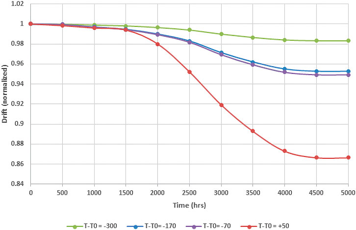
FIGURE 6. Extrapolation of the drift (normalized) due to high-temperature operation.
3.5 Results of the HTIR-TC instability model calculations
The total instability (in percent, as calculated by the HTIR-TC instability model) caused by neutron fluence and high-temperature operation over 125 EFPDs was obtained by adding the percent change due to neutron fluence and the percent change due to high-temperature operation.
Comparison of these results (calculated by the HTIR-TC instability model) against the observed instability can be made by examining the instability data obtained for HTIR-TCs 1-12, 1-13, 1-14, and 3-5 in the AGR 5/6/7 test, in which the instability was caused by both neutron fluence and high-temperature operation.
The data show that, for 125 EFPDs, the total instability due to neutron fluence and high-temperature operation was approximately −3.3% for HTIR-TCs 1-12 and 1-13, −3.5% for HTIR-TC 1-14, and −8.7% for HTIR-TC 3-5. Note that there was no apparent instability for HTIR-TC 3-5 over the first 1,200 h at ∼1,500°C, meaning that HTIR-TCs can be used to measure such high temperatures without experiencing drift and inhomogeneity. These values compare well with the calculated values shown in Table 2.
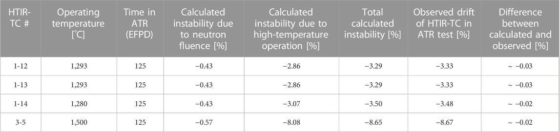
TABLE 2. Total calculated HTIR-TC instability due to neutron fluence and high-temperature operation. Comparison between instability model and actual measured drift is shown.
4 HTIR-TC instability model applied to operating thermal BWR or PWR
HTIR-TC drift in commercial, well-moderated thermal power reactors can be conservatively estimated by employing the HTIR-TC instability model and the same 2,200 m/s thermal neutron cross section for determining the Seebeck coefficient reduction factor as was used for the ATR HTIR-TC drift calculation. As described in Step 9 of Section 3.4.1, the average cross section for determining the reduction factor in a reactor is obtained by modifying the 2,200 m/s cross section, using Equation 9 to account for the power reactor’s thermal neutron temperature. The cross-section coefficient, C1, for calculating drift due to neutrons thermalized at BWR and PWR temperatures is shown in Table 3. Since commercial BWRs and PWRs are primarily thermal flux reactors, the drift due to fast neutron irradiation can be neglected.
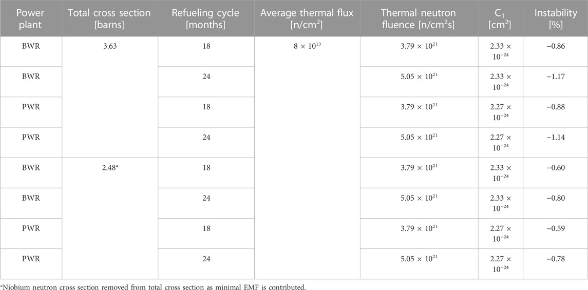
TABLE 3. Calculated instability in a commercial power reactor.
The expected thermal neutron fluence, φt, for a TC located in-core in a commercial power reactor is approximately 3.8 × 10²¹ n/cm2 for an 18-month refueling cycle and ∼5.1 × 10²¹ n/cm2 for a 24-month cycle, based on the average thermal neutron flux of 8 × 10¹³ n/cm2s. The expected TC drift for this level of thermal neutron exposure in a BWR or PWR can be calculated by assuming the TC to have been installed as a standalone TC, and the neutron flux incident on the TC to be constant in the region where the temperature is changing. For such an installation in a BWR or PWR, the drift can be calculated using the following simplified equation:
where C1(BWR) = 2.33 × 10⁻²⁴ cm2, C1(PWR) = 2.27 × 10⁻²⁴ cm2. The results of this calculation are shown in Table 4. Another option to consider is the removal of the Nb neutron absorption cross section, as a negligible amount of EMF is generated in that thermoelement. Mo would then be considered the sole EMF generator, leaving the neutron absorption cross section of the HTIR-TC as 2.48 b.
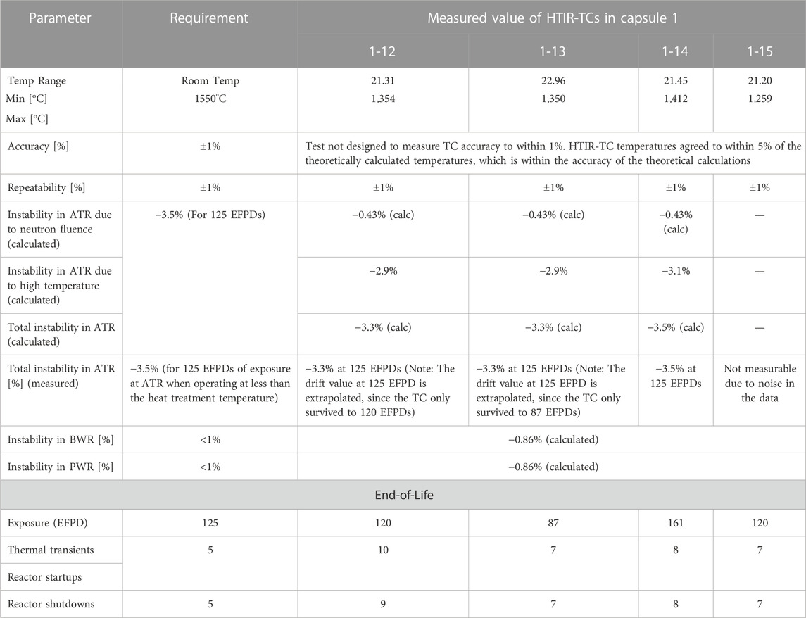
TABLE 4. Summary of HTIR-TC performance in Capsule 1 during the AGR 5/6/7 test.
Note that for HTIR-TCs operating in a BWR or PWR, the only drift that occurs is due to neutron exposure. The drift due to high-temperature operation in a BWR or PWR is negligible since the operating temperature is far below the heat treatment temperature. The typical operating reactor temperature at 100% power is 300°C for a BWR and 315°C for a PWR, while the heat treatment temperature for these HTIR-TCs is 1,450°C. Thus, for normal full-power operation, the difference between the heat treatment temperature and the operating temperature (>1,100°C) is very large and would produce a negligible high-temperature drift. Also note that even if the TC was measuring a BWR/PWR accident temperature of 1,000°C, the difference with the heat treatment temperature would be > 400°C. Therefore, according to the HTIR-TC instability model, the high-temperature drift would be negligible, especially since the accident time is generally brief.
5 Summary of HTIR-TC instability performance
Tables 4, 5 summarize the results of the HTIR-TC test measurements and the requirements for the HTIR-TC calibrations. Tables 4, 5 are associated with the AGR 5/6/7 Capsule 1 results, and the AGR 5/6/7 Capsule 3 results, respectively.
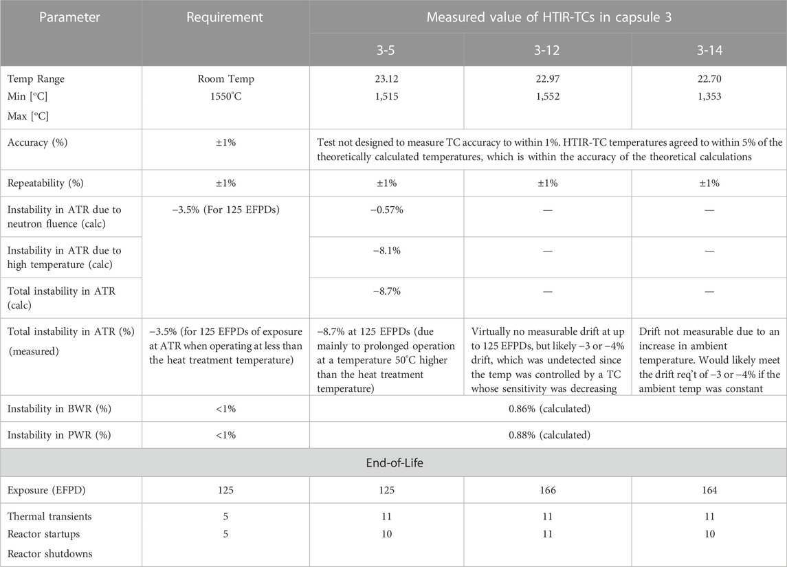
TABLE 5. Summary of HTIR-TC performance in Capsule 3 during the AGR 5/6/7 test.
Results of the qualification test enabled the following observations:
1. Range: The HTIR-TCs were able to measure temperatures ranging from room temperature to ∼1,550°C. That was the highest temperature ever measured and withstood by any TC in a high-flux reactor environment. Note that, due to melting point restrictions, type-N TCs, which are typically used for high-temperature measurements, can only measure temperatures of up to approximately 1,300°C—nearly 300°C lower than for the HTIR-TCs.
2. Accuracy: The accuracy of the HTIR-TCs was determined via an out-of-pile calibration test in which the HTIR-TC temperature measurement was compared to that of a type-B TC National Institute of Standards and Technology (NIST) standard (Skifton et al., 2018) utilizing ASTM comparative methods under ASTM E220. The general accuracy of each HTIR-TC was statistically found to be either ±1°C or ±0.4% of the temperature reading, whichever was greater.
3. Instability: This aspect of performance could not be accurately determined, due to random fluctuations in the data caused by variations in ambient temperature–arising from the capsule blanket He/Ne gas mixture and/or flow rate. The four HTIR-TCs in Capsule 1 behaved as expected regarding drift. The drift of the HTIR-TCs in Capsule 1 (i.e., 1-12, 1-13, and 1-14) met the −3.5% requirement at 125 EFPDs, though some failed prior to the 125 EFPD period, having been subjected to a large (more than the specified) number of severe thermal transients. The three HTIR-TCs in Capsule 3 reflected different drift performance trends. HTIR-TC 3-14 showed an upward trend that was synchronous with four similarly located type-N TCs—a trend attributed to a gradual ambient temperature increase caused by changes in the passive gas system. The performance data indicate that, had this increase in ambient temperature not occurred, the TC would have behaved as expected. HTIR-TC 3-12, along with two other type-N TCs, behaved normally and showed virtually no drift and inhomogeneity. HTIR-TC 3-5 behaved as expected for an exposure of 50 EFPDs. The performance data indicate that HTIR-TC 3-5 would have instead shown between −3% and −4% instability at an exposure of 125 EFPDs had the ambient temperature held steady, but instead showed a large drop of −8.7% at 125 EFPDs. The cause of this large sensitivity decrease was due to prolonged operation at a temperature 50°C higher than the heat treatment temperature. The technical reason for this is not well understood but is likely due to diffusion of impurities into the thermoelements, due to prolonged operation at high temperatures. Note that the instability measurements were made at high ATR power, and that the HTIR-TC drift and inhomogeneity values calculated by the instability model described in this report apply only to high-temperature operation (>1,050°C). No HTIR-TC drift measurements were made at low ATR power, and no experimental results are available regarding low-temperature operation.
6 Conclusion
The HTIR-TC instability model was developed to calculate TC drift and inhomogeneity. It was determined that, based on the experimental data, HTIR-TC instability was due to both thermal and fast neutrons having caused a reduction in the thermoelements’ Seebeck coefficients, as well as to prolonged high-temperature operation. The thermal neutrons change the Seebeck coefficient by transmuting the thermoelements via absorption of thermal neutrons, and the fast neutrons change the Seebeck coefficient primarily by altering the thermoelements’ lattice structure through fast neutron bombardment. In addition, prolonged high-temperature operation can change the metallurgical structure of the thermoelements and cause drift and inhomogeneity. Constants for these effects were determined from the available experimental data and then used, along with estimates of the temperature and neutron flux profiles across the TC cables, to determine the pre- and post-irradiation TC EMFs and calculate the TC drift and inhomogeneity due to neutron fluence and prolonged high-temperature operation. The calculation showed that, for 125 EFPDs of exposure in the ATR test fixture, the drift was −3.3% for HTIR-TCs 1-12 and 1-13 in Capsule 1, -3.5% for HTIR-TC 1-14 in Capsule 1, and -8.7% for HTIR-TC 3-5 at a higher temperature in Capsule 3. The calculated instability matched the observed drift for the HTIR-TCs in Capsule 1, though this was not the case for Capsule 3, due to the uncontrolled temperature increase it underwent.
Data availability statement
The raw data supporting the conclusion of this article will be made available by the authors, without undue reservation.
Author contributions
RS designed the entirety of the instability model utilized in mapping HTIR-TC use in the reactor and/or fuels experiments. He designed each figure and table to provide clarification to the text.
Funding
United States Department of Energy—Office of Nuclear Energy. Under the Nuclear Energy Enabling Technology (NEET) Advanced Sensors and Instrumentation (ASI) program. Nuclear grade sensors are developed to high TRL level under this program. Prepared for the U.S. Department of Energy Office of Nuclear Energy Under DOE Idaho Operations Office Contract DE-AC07-05ID14517.
Conflict of interest
The author declares that the research was conducted in the absence of any commercial or financial relationships that could be construed as a potential conflict of interest.
Publisher’s note
All claims expressed in this article are solely those of the authors and do not necessarily represent those of their affiliated organizations, or those of the publisher, the editors and the reviewers. Any product that may be evaluated in this article, or claim that may be made by its manufacturer, is not guaranteed or endorsed by the publisher.
Author disclaimer
This manuscript has in part been authored by Battelle Energy Alliance, LLC under Contract No. DE-AC07-05ID14517 with the United States Department of Energy. The United States Government retains and the publisher, by accepting the paper for publication, acknowledges that the United States Government retains a non-exclusive, paid-up, irrevocable, world-wide license to publish or reproduce the published form of this manuscript, or allow others to do so, for United States Government purposes. STI Number: INL/JOU-23-71078.
References
ATR National Scientific User Facility (2009). Advanced test reactor national scientific user facility users guide. Idaho National Laboratory. INL/EXT-08-14709. Available at: https://nsuf.inl.gov/File/ATRUsersGuide.pdf.
Daw, J. E., Crepeau, J. C., Rempe, J. L., Wilkins, S. C., Knudson, D. L., and Condie, K. G. (2007). “Initial results from investigations to enhance the performance of high temperature irradiation-resistant thermocouples,” in J jpn soc mech eng (JSME), invited paper for 15th international conference on nuclear engineering (ICONE15) special edition (Nagoya, Japan. April 22-26, 2007. Available at: https://www.researchgate.net/publication/282614012_Initial_Results_from_Investigations_to_Enhance_the_Performance_of_High_Temperature_Irradiation-Resistant_Thermocouples.
Daw, J. E. (2009). “High temperature irradiation-resistant thermocouple performance improvements,” in Proc. Sixth American nuclear society international topical meeting on nuclear plant instrumentation, control, and human-machine interface Technologies (Knoxville, TN: NPIC&HMIT). April 5-9, 2009. Available at: https://inldigitallibrary.inl.gov/sites/sti/sti/4235634.pdf.
Daw, J. E., Rempe, J. L., Knudson, D. L., Wilkins, S. C., and Crepeau, J. C. (2008). Extension wire for high temperature irradiation resistant thermocouples. Meas. Sci. Technol. 19, 045206. doi:10.1088/0957-0233/19/4/045206
Dayal, Y., and Jensen, C. (2019). Guidelines for developing and qualifying instrumentation systems at Idaho national laboratory. Idaho National Laboratory. Document ID: GDE-947 Rev 0, Available upon request.
Hawkes, G. L. (2019). “Thermal model details and description of the AGR-5/6/7 experiment,” in Proc. International congress on advances in nuclear power plants, ICAPP 2019 (France, Juan-les-pins. May 12-15, 2019. Available at: https://www.osti.gov/biblio/1599861-thermal-model-details-description-agr-experiment.
Jensen, C. (2007). FY17 report for instrumentation for the transient testing program. Idaho National Laboratory. INL/EXT-17-43444. Available at: https://inldigitallibrary.inl.gov/sites/sti/sti/Sort_3449.pdf.
Kim, Y. G., Song, C. H., Gam, K. S., and Yang, I. (2009). Change in inhomogeneity with temperature between 180° C and 950° C in base-metal thermocouples. Meas. Sci. Technol. 20 (7), 075102. doi:10.1088/0957-0233/20/7/075102
Palmer, A. J., Petti, D., and Grover, S. B. (2014). “Advanced gas reactor (AGR)-5/6/7 fuel irradiation experiments in the advanced test reactor,” in International congress on advances in nuclear power plants (ICAPP), 1, 257–266. Available at: https://inldigitallibrary.inl.gov/sites/sti/sti/6064457.pdf.
Palmer, A. J., Skifton, R. S., Haggard, D. C., and Swank, W. D. (2019). “Performance of custom-made very high temperature thermocouples in the advanced gas reactor experiment AGR-5/6/7 during irradiation in the advanced test reactor,” in Animma 2019 - international conference on advancements in nuclear instrumentation measurement methods and their applications (Portoroz, Slovenia. Jul 17-21, 2019. Available at: https://www.aconf.org/conf_161818.html.
Palmer, A. J., Skifton, R. S., Haggard, D. C., Swank, W. D., and Scervini, M. (2019). “Development and testing of thermocouples for the advanced gas reactor fuel experiment AGR-5/6/7,” in Proc. 11th nuclear plant instrumentation, control and human-machine interface Technologies (NPIC&HMIT 2019) (Orlando, FL, 1013–1027. (February). Available at: https://www.ans.org/pubs/proceedings/article-45868/.
Palmer, A. J. (2015). “Summary of thermocouple performance during advanced gas reactor fuel irradiation experiments in the advanced test reactor and out-of-pile thermocouple testing in support of such experiments,” in Proc. 2015 4th international conference on advancements in nuclear instrumentation measurement methods and their applications (ANIMMA) (Lisbon: Portugal), 1–9. (April). doi:10.1109/ANIMMA.2015.7465501
Palmer, J., Skifton, R. S., Pham, B., and Hawkes, G. (2021). “Summary of thermocouple performance in the advanced gas reactor experiment AGR-5/6/7 during irradiation in the advanced test reactor,” in ANIMMA international conference (Prague, Czech Republic. (June). Available at: https://www.osti.gov/servlets/purl/1822921.
Pham, C. B. T. (2021). AGR 5/6/7 irradiation test final as-run report. Idaho National Laboratory. INL/EXT-21-64221. Available at: https://inldigitallibrary.inl.gov/sites/sti/sti/Sort_52944.pdf.
Pham, C. B. T., Sterbentz, J. W., Hawkes, G. L., Scates, D. M., and Palmer, J. (2020). AGR-5/6/7 experiment monitoring and simulation progress. Idaho National Laboratory. INL/EXT-19-55429. Available at: https://www.osti.gov/servlets/purl/1689160.
Rempe, J. L., Knudson, D. L., Condie, K. G., Wilkins, S. C., and Daw, J. E. (2008). “Long duration performance of high temperature irradiation resistant thermocouples,” in Proc. International conference on advanced power plants (ICAPP 2007) (Nice, France. May 2008. Available at: https://inldigitallibrary.inl.gov/sites/sti/sti/3693710.pdf.
Rempe, J. L., Knudson, D. L., Condie, K. G., and Wilkins, S. C. (2006). “Evaluation of specialized thermocouples for high-temperature in-pile testing,” in Proc. 2006 int. Congress advances in nuclear power plants (ICAPP’06) (Reno, Nevada. June 4–8, 2006. Available at: https://www.osti.gov/servlets/purl/911567.
Rempe, J. L., Knudson, D. L., Condie, K. G., and Wilkins, S. C. (2007). “Long duration performance of high temperature irradiation resistant thermocouples.” INL/CON-06-11879,” in Proc. International conference on advanced power plants (ICAPP 2007) (Nice, France. May 13-18, 2007. Available at: https://www.osti.gov/biblio/912437.
Rempe, J. L., Knudson, D. L., Condie, K. G., and Wilkins, S. C. (2006). Thermocouples for high-temperature in-pile testing. Nucl. Technol. 156 (3), 320–331. doi:10.13182/NT06-A3794
Rempe, J. L., and Wilkins, S. C. (2005). “High temperature thermocouples for in-pile applications,” in Proc. 11th int. Topl. Mtg. On nuclear reactor thermal-hydraulics (NURETH-11) (Avignon, France. October 2–6, 2005. Available at: https://www.researchgate.net/publication/238099701_HIGH_TEMPERATURE_THERMOCOUPLES_FOR_IN-PILE_APPLICATIONS.
Rempe, J. L., and Wilkins, S. C. (2005). Specialized thermocouples for high temperature in-pile applications. Idaho National Laboratory. INEEL/EXT-05-02576. Available at: https://www.researchgate.net/publication/286778226_Specialized_Thermocouples_for_High_Temperature_In-Pile_Applications.
Riley, B. P., Sikorski, E., Skifton, R., Li, L., and Jaques, B. J. (2019). “Development and performance of high temperature irradiation resistant thermocouples,” in Materials for nuclear applications (Portland, OR: Materials Science & Technology). September 29 – October 3, 2019.
Riley, S., Holloway, K., Bateman, A., Skifton, R., and Jaques, B. J. (2023). Influence of microstructure and phase morphology on the stability of high temperature irradiation resistant thermocouples. Mat Sci Eng A 112. doi:10.1016/j.mtcomm.2023.105972
Riley, S., Perrine, B., Sikorski, E., Li, L., Skifton, R., and Jaques, B. (2020). “Performance of niobium and molybdenum alloys for high temperature sensing applications,” in Proc. 2020 TMS annual meeting & exhibition (San Diego, CA: Refractory Metals).
Scates, D., Reber, E. L., and Miller, D. (2020). Fission gas monitoring for the AGR-5/6/7 experiment. Nucl. Eng. Des. 358, 110417. doi:10.1016/j.nucengdes.2019.110417
Scervini, M., Rae, C., and Lindley, B. (2013). “Transmutation of thermocouples in thermal and fast nuclear reactors,” in Proc. 2013 3rd international conference on advancements in nuclear instrumentation, measurement methods and their applications (ANIMMA) (Marseille, France, 1–8. doi:10.1109/ANIMMA.2013.6727900
Sikorksi, E. (2021). Computational modeling towards accelerating accident tolerant fuel concepts and determining in-pile fuel behavior. Ph.D. Thesis. Boise State University, 93–117. Chapter 5. doi:10.18122/td.1873.boisestate
Skifton, R. (2021a). “A first principle look at the electromotive force generation from molybdenum and niobium alloys,” in Proc. 12th nuclear plant instrumentation, control and human-machine interface Technologies (NPIC&HMIT 2021) (Providence, RI, 585–591. (June 2021). doi:10.13182/T124-34537
Skifton, R. (2021b). High temperature irradiation resistant thermocouple qualification requirement report. Idaho National Laboratory. INL/EXT-21-63269, 2021. Available at: https://inldigitallibrary.inl.gov/sites/sti/sti/Sort_53355.pdf.
Skifton, R., Palmer, J., and Hashemian, A. (2021). Optimized high-temperature irradiation resistant thermocouple for fast-response measurements. EPJ Web Conf. 253, 06004. doi:10.1051/epjconf/202125306004
Skifton, R. S. (2021c). Function and operational requirements for high temperature irradiation resistant thermocouples (No. INL/EXT-21-63173-Rev001). Idaho Falls, ID (United States): Idaho National Lab.(INL.
Skifton, R. S. (2019). Out-of-pile performance of high temperature irradiation resistant and cladding thermocouples. Idaho National Laboratory. INL/EXT-19-55295, 2019. Available at: https://inldigitallibrary.inl.gov/sites/sti/sti/Sort_19912.pdf.
Skifton, R. S., Palmer, A. J., Davis, K., Calderoni, P., Sikorski, E., and Corbett, D. (2019). “Summary of high temperature irradiation resistant thermocouple standardization tests,” in Proc. 11th nuclear plant instrumentation, control and human-machine interface Technologies (NPIC&HMIT) (Orlando, FL. INL/CON-18-51789-Rev. 0 (February). Available at: https://www.osti.gov/biblio/1497074.
Skifton, R. S., Palmer, J., and Calderoni, P. (2018). Optimization of heat treatment and calibration procedures for high temperature irradiation resistant thermocouples. Instrum. Sci. Techno 46 (4), 349–363. doi:10.1080/10739149.2017.1389754
Wescott, C. H. (1962). Effective cross section values for well-moderated thermal reactor spectrum. Atomic Energy of Canada Limited. AECL-1101. Available at: https://inis.iaea.org/search/search.aspx?orig_q=RN:41057250.
White, W. P. (1906). The constancy of thermoelements. Phys. Rev. Ser. I) 23 (6), 449–474. doi:10.1103/physrevseriesi.23.449
Wilkins, S. C., and Evans, R. P. (2005). Assessment of high-temperature measurements for use in the gas test loop. Idaho National Laboratory. INL/EXT-05-00298. Available at: https://inldigitallibrary.inl.gov/sites/sti/sti/3480227.pdf.
Wilkins, S. C. (1988). “Low cross-section Mo-Nb thermocouples for nuclear application: The-State-of-the-Art,” in 5th symp of space nuclear power systems (Albuquerque, NM, 1. (January). Available at: https://www.osti.gov/servlets/purl/5651355.
Wilkins, S. C., and Schooley, J. F. (1992). “Characterization and materials-compatibility tests of molybdenum-niobium thermocouples,” in Proc. 7th int. Symp. Temperature: Its meas and control in science and industry (Toronto, Canada, 728–630. 6, no. 1, (January). Available at: https://www.tib.eu/en/search/id/BLCP:CN005065549/Characterization-and-material-compatibility-tests?cHash=7aa5d556756a2bfc53f39937b7c35b3d.
Keywords: thermocouple, in-pile, sensor, irradiation resistant, high temperature, nuclear, reactor temperature, fuel qualification test
Citation: Skifton R (2023) High-temperature irradiation-resistant thermocouple instability model for in-pile reactor use. Front. Energy Res. 11:1099584. doi: 10.3389/fenrg.2023.1099584
Received: 16 November 2022; Accepted: 13 April 2023;
Published: 09 May 2023.
Edited by:
John Darrell Bess, JFoster & Associates, LLC (JFA), United StatesReviewed by:
Pavel Tsvetkov, Texas A&M University, United StatesOrest Kochan, Lviv Polytechnic, Ukraine
Alexey Soldatov, Tomsk Polytechnic University, Russia
Bojan Petrovic, Georgia Institute of Technology, United States
Copyright © 2023 Skifton. This is an open-access article distributed under the terms of the Creative Commons Attribution License (CC BY). The use, distribution or reproduction in other forums is permitted, provided the original author(s) and the copyright owner(s) are credited and that the original publication in this journal is cited, in accordance with accepted academic practice. No use, distribution or reproduction is permitted which does not comply with these terms.
*Correspondence: Richard Skifton, cmljaGFyZC5za2lmdG9uQGlubC5nb3Y=