 Ilia Shojaeinasab Chatroudi1
 Meysam Atashafrooz1
 Hayder I. Mohammed2Azher M. Abed3
 Pouyan Talebizadehsardari4*
- 1Department of Mechanical Engineering, Sirjan University of Technology, Sirjan, Iran
- 2Department of Physics, College of Education, University of Garmian, Kalar, Iraq
- 3Air Conditioning and Refrigeration Techniques Engineering Department, Al-Mustaqbal University College, Babylon, Iraq
- 4Centre for Sustainable Energy Use in Food Chains, Institute of Energy Futures, Brunel University London, Uxbridge, United Kingdom
To overcome the weak conduction heat transfer of phase change materials (PCM), this investigation aimed to assess the behavior of a double-tube latent heat storage unit with circular fins through the charging process. The influence of free convection in the presence of fins of various arrangements and sizes was comprehensively studied. The geometrical characteristics of the fins, i.e., their size and number, were assessed to optimize their performance. Moreover, a sensitivity assessment was performed on the characteristics of the heat transfer fluid passing through the inner tube, i.e., the Reynolds number and temperature. Charging time diminished by 179% when nine 15 mm fins were added compared with the finless scenario, assuming the same phase change materials volume. Moreover, the system’s thermal recovery rate improved from 20.5 to 32.9 W when nine fins with the heigth of 15 mm were added. The use of more fins improved the thermal behavior of the phase change materials because of the higher total fin area. The melting time and heat storage rate changed by 76% and 71%, respectively, for the system with 19 fins compared with those with four fins. Moreover, the outcomes indicated that a higher heat storage rate can be achieved when the working medium’s faster flow and inlet temperature were used.
1 Introduction
The roadmap of fossil fuels has led governments to look for replacements (Zhang et al., 2016; Wen et al., 2021). With environmental issues directly impacting human quality of life, the future of global economies depends on immediate investigations of renewable energies (Liu et al., 2022; Zhou et al., 2019). Thus, efforts have focused on developing technologies based on clean and available energy sources, such as solar, wind, and geothermal (Mu et al., 2021; Lu et al., 2022; Mabugu and Inglesi-Lotz, 2022). Thermal energy storage (TES) units have been implemented in many applications to efficiently control renewable energies and compensate for inconsistencies between power sources and demand (Feng et al., 2022; Sohani et al., 2023). Enormous attention has been focused on latent heat storage (LHS) systems recently due to their higher energy density compared with sensible heat storage systems using phase change materials (PCMs) (Mahdi et al., 2019). However, insufficient PCM thermal conductivity limits LHS applications (Zhang et al., 2018; Guo et al., 2022). In this regard, the use of different fin configurations (Chang et al., 2022; Najim et al., 2022), heat exchanger modifications (Smith et al., 1980; Talebizadehsardari et al., 2021), multiple PCMs (Sardari et al., 2019), nanoparticles (Mahdi and Nsofor, 2017b; Said et al., 2019; Huang et al., 2021), and high-conductive foams (Mahdi et al., 2021; Cui et al., 2022) may help to solve this problem.
Numerous studies have been carried out to modify PCM thermal characteristics in LHS systems with the aim of achieving an acceptable heat storage/retrieval rate. Eisapour et al. (2022) modified the geometry of a double-tube PCM container using a wavy profile with different amplitudes for the inner pipe considering straight and twisted pipes to improve the thermal energy exchanged between the heat transfer fluid and the PCMs. Likewise, they considered straight and conical forms for the container. They found that using an ascending wavy tube in a conical container enhanced the melting process more than with the other proposed cases. In terms of the use of nanoparticles in the PCM, Huang et al. (2021) empirically studied the addition of aluminum and copper nanoparticles to the PCM, which in this instance was paraffin wax, at various concentrations, ranging from 1% to 5%. They showed that nanoparticle concentrations of 1% and 2.5% resulted in superior heat transfer compared with other concentrations. Sardari et al. (2021) assessed a plate-shaped thermal exchanger with a zigzag design for energy storage to enhance the thermal exchange area at a particular PCM mass. They showed that higher numbers of zigzags were associated with a faster melting rate due to the greater heat transfer area. Ma et al. (2020) studied the effects of nanoparticles dispersed into paraffin wax, showing that nanoparticle application enhances the solidification procedure and diminishes entropy formation. Ahmed et al. (2022) investigated different geometry modifications and nanoparticle addition techniques in a PCM container during melting. They performed a numerical simulation on a wavy circular cylinder containing nano-additives and showed that the melting rate augments with increasing nanoparticle concentration. Ghalambaz et al. (2022) assessed a heat recovery unit equipped with a compound porous medium (nano-PCM) and wavy tubes. They showed the advantages of the porous medium and nanoparticle utilization when a modified heat exchanger was used.
As one of the most effective approaches for improving heat storage performance, fins have been widely used to enhance the thermal behavior of the heat exchanger (Eslami et al., 2021). Khedher et al. (2022) examined the impact of dimple-fin implementation in a double-pipe heat storage unit. They examined the impact of fins’ numbers, sizes, and arrangements considering the same volume of the fins toward a higher heat storage rate. Moreover, the arrangement and position of the fins have a noticeable impact on heat storage efficiency. Najim et al. (2022) examined the influence of non-uniform circular fins with different diameters in a vertical triple-tube LHS unit to improve convection influence at the base of a heat recovery system. Moreover, they presented a novel configuration of fin distribution using a flat circular fin at the bottom of the storage unit with uniform fin locations along the vertical pipe. They found the best algorithm for the fin’s size to achieve maximum heat storage performance. Moreover, a circular fin stuck to the heat exchanger’s bottom surface with a uniform fin array showed faster melting than a non-uniform fin array without the fin at the bottom. Al-Mudhafar et al. (2021) considered using an innovative T-fin configuration in a horizontal PCM shell-and-tube thermal exchanger using two-dimensional numerical analysis. They showed that the charging rate for the case with innovative T-fins is 33% higher than that of the case using regular longitudinal fins. M. J. Ebrahimnataj Tiji et al. (2022) analyzed the impact of T-fins in a vertically oriented triplex-tube thermal exchanger. They showed that the T-shaped fins exhibit superior melting performance as they cover a higher volume of the PCM container and thus form a higher thermal exchange area. Hosseini et al. (2015) numerically and experimentally studied the effect of longitudinal fins with different dimensions in a double-tube heat exchanger holding PCM during the melting process. They indicated that longer fins improve melting performance. Pizzolato et al. (2017) improved the configuration of fins added to a double-tube system to analyze the free convection effect during melting. They presented the advantages of the fin configuration in terms of the charging behavior of the PCM. Sanchouli et al. (2022) studied a horizontal double-pipe heat storage unit equipped with grid annular fins assuming the constant volume of the fins. They showed the advantage of the grid fins compared with the solid fins and demonstrated a reduction of 27%–69.5% in the melting time by changing the fin spacing. They also showed that by the non-uniform usage of the grid fins, an extra 16% reduction can be achieved in the melting time. Bahlekeh et al. (2022) targeted a vertical triple-tube heat storage system with an optimum fin array and showed the advantages of adding an extra fin to the bottom of the heat exchanger to improve the natural convection effect.
Although several studies have investigated the use of circular fins in double-pipe heat storage systems, the optimization of the fin arrangement, assuming the constant volume of the fins, has rarely been discussed. Therefore, in the current study, the arrangement of a double-tube latent heat storage (DTLES) system with circular fins is optimized in a vertical orientation by analyzing the fins' geometrical characteristics and the working fluid. Different sizes and numbers of the fins are assessed to reduce the charging time of the PCM inside the annulus of the container, assuming the constant volume of the fins. In other words, the aim is to determine how to arrange a constant volume of metal fins inside a double-tube heat exchanger by changing the height-to-width ratio and the number of fins to achieve the highest heat storage rate. Moreover, the Reynolds number and inlet temperature of the working fluid are investigated to determine the system's behavior at different operating conditions. This study presents guidelines for designing and manufacturing double-tube thermal storage systems for practical applications.
2 Description of the problem
This investigation analyzed a vertical DTLHS heat exchanger with circular fins to find the best performance during melting. The working fluid (water) was passed through the system from the middle tube while the annulus was filled with PCM. The fins were linked to the inner tube inside the PCM domain to help heat exchange between the tubes from the fluid to the PCM. The length of the DTLES system was 250 mm, with inner and outer diameters of 20 and 40 mm, respectively. For the optimization process, the geometrical characteristics of the fins were assessed assuming identical volumes of the fins. Thus, owing to the constant volume of the heat exchanger, the same volume was applied for the PCM. For the geometrical parameters, the number of fins and the height of the fins are assessed. It should be noted that for a constant volume of the fins, the fins’ height and thickness are dependent; therefore, owing to the closer relationship of afin’s area with height rather than thickness, the calculations were performed based on fins’ height in this study. In addition to the geometrical parameters, a sensitivity analysis was performed for the characteristics of the working fluid, including the temperature and Reynolds number. The schematic of the proposed system is illustrated in Figure 1A. Owing to the nature of the studied geometry and the lack of circumferential flow, the computational domain was considered axisymmetric, as illustrated in Figure 1A, which also presents the heat exchanger dimensions.
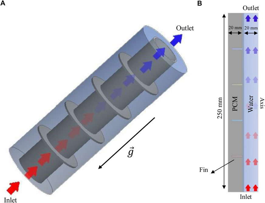
FIGURE 1. Schematic of the system presented as three-dimensional (A) and two-dimensional (B) axisymmetric models.
2.1 Geometrical parameters and material properties
Three different values were chosen for the heights of the fins (5, 10, and 15 mm), considering nine fins for the number of the fins. After examining the fin’s height effect, heights of 4, 9, 15, and 19 mm were examined. In the fin’s parameter analysis, the Reynolds number and inlet temperature of the water were 1,000 and 50°C, respectively. Finally, for the best case, different Reynolds numbers (500, 1,000, and 2,000) and various inlet temperatures (45°C, 50°C, and 55°C) were chosen for the working fluid, which is considered to be water. It should be noted that the properties of water depend on its inlet temperature. RT35 was selected for the PCM as it has several advantages compared with other available PCMs; for instance, it has a higher melting point than other PCMs, making it more suitable for high-temperature applications. RT35 has a lower thermal conductivity than other PCMs, making it more efficient at storing and releasing heat and it is non-toxic and safe to use in contact with food and skin. Further, RT35 is more durable and has a longer lifespan than other PCMs. The properties of RT35 are displayed in Table 1.
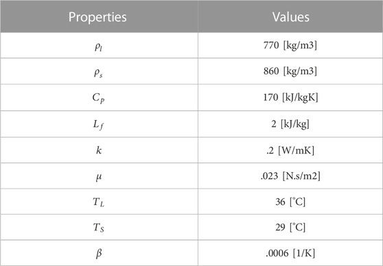
TABLE 1. Thermodynamic characteristics of the applied PCM (Rubitherm, 2018).
3 Mathematical modeling
To represent the phase change process of PCM, the enthalpy technique established by Brent et al. (Mahdi and Nsofor, 2017a) was applied. In this scheme, the liquid part was assumed to cover all the cells in the initial state of the computational field. The velocity and temperature were considered uniform for the working fluid at the inlet, as shown in Figure 1. A pressure outlet was also selected for the working fluid’s outlet. An adiabatic boundary condition was chosen for the PCM enclosure to eliminate the ambient effect. The middle wall between the PCM and the working fluid was considered to be copper. The inner and outer tubes were 1 mm thick, so the thickness of the middle wall was 2 mm. The no-slip boundary condition was also assumed for the walls.
To formulate the governing equations, the following statements were assumed (Shahsavar et al., 2019):
• Management of density variation by implementing the Boussinesq approximation;
• Two-dimensional axisymmetric model for the computational domain;
• Transient, laminar, and incompressible fluid flow for the liquid PCM and working fluid;
• Gravity assumed to be in a downward direction; and
• Assumption of no velocity slips at solid boundaries.
Thus, the continuity, momentum, and energy are given as (Wang et al., 2015):
The parameter (
The factor of the mushy area
The source term
The heat storage rate was measured as:
where
4 Numerical model
FLUENT software was used to carry out the numerical simulations with a simple algorithm to evaluate the thermal performance of PCM storage. The author’s previous work presented more details about the numerical method (Sardari et al., 2019). The mesh was generated using ANSYS Design Modeler software. These studies should be performed before the primary investigation to achieve problem independence from the mesh size and time step size. For this purpose, various sizes (.1, .2, and .4 mm) were considered for the mesh, and the liquid fraction and temperature results are presented in Figure 2. The results were almost identical, and the difference occurred at the end of the process when most of the PCM melted. As shown, the results for mesh sizes of .1 and .2 mm were similar, and the difference in the melting time reaching the melting fraction of 95% was less than 1%. Therefore, a mesh size of .2 mm was chosen. Note that the time step size was .1 s in the study of the mesh size.
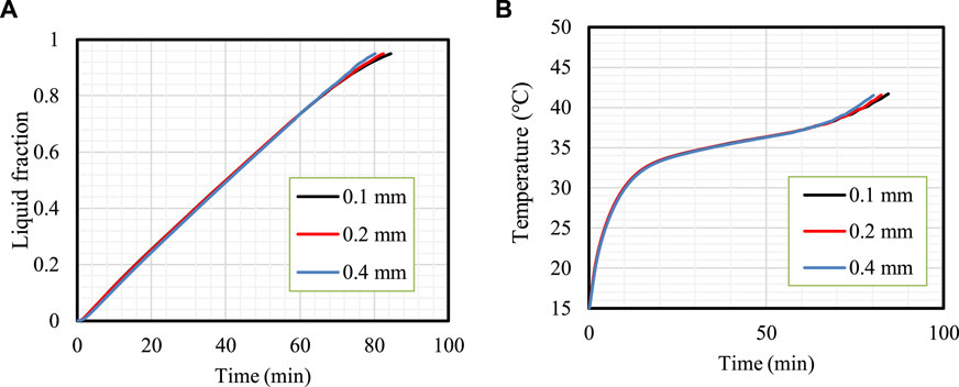
FIGURE 2. Mesh independence analysis. Variation in the liquid fraction (A) and mean temperature (B) for different mesh sizes.
The time step size variation is featured in Figure 3, which shows the liquid fraction (Figure 3A) and mean temperature (Figure 3B) variations. The results for the time step sizes of .05 and .1 s are almost similar; thus, .1 s was chosen as the size of the time step.
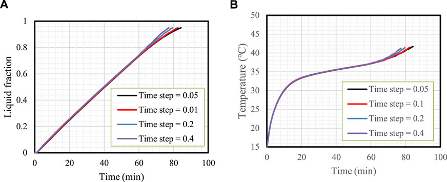
FIGURE 3. Time step size analysis. Variation in the liquid fraction (A) and mean temperature (B) for different time step sizes.
To verify the CFD code using a similar geometry with a similar PCM, the experimental study of Longeon et al. (2013) was chosen. They examined the melting process in a vertical DTLHE system using RT35 as the PCM in the annulus and water as the working fluid inside the inner tube. The inner and outer diameters of the system are 15 and 44 mm, respectively, and the container was filled with a 480 g PCM. The water inlet temperature was set at 53°C. The average water velocity inside the tube was assumed to be .01 m/s, equivalent to a Reynolds number of 2,300. Figure 4 shows the mean temperature of the PCM achieved in this study compared with the experimental study of Lengeon et al. They used 48 thermocouples to capture the temperature in the entire domain. As shown, the maximum error found between the numerical and the previous experimental results was 1.5%; the results obtained in the current study are in excellent agreement with those captured by Lengeon et al., which proves the validity of the current study.
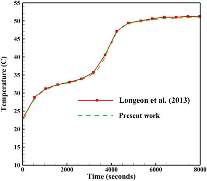
FIGURE 4. Assessment of the charging period acheived in the present study compared with the study of Longeon et al. (2013).
5 Results and discussions
The fins’ length influences the charging process and was investigated first assuming a constant fins’ size and number compared with the finless case. Fin number was also studied, starting with four fins and then increasing the number by keeping all the fins’ volumes constant in all the cases. The effect of the fluid charactristics, indicated by the Reynolds number and inlet temperature, was also examined. The primary purpose of this study was to find a way to use many fins instead of a few to enhance the unit’s performance. This study shows a novel role in this area as a step ahead concerning other general studies to create a modified finned double-tube storage unit.
5.1 Effect of fin height
Figure 5A shows the melting contour of the system with different fin dimensions (fin size and number are constant in all cases) compared with that of the finless system. The first row of Figure 5A illustrates the charging process of the TES in the finless case at various time steps (up to 5,400 s). During early charging progression, a thin layer of molten PCM formed on the wall of the PCM container, creating a barrier between the wall and the solid PCM. The liquid layer gradually thickened to gain more heat from the HTF. Because of the density difference between the PCM phases and the buoyancy effect, the liquid phase gathered at the top of the domain, leaving the solid phase at the lower levels. Within 5,400 s of the charging progression, only 43% of the PCM was melted.
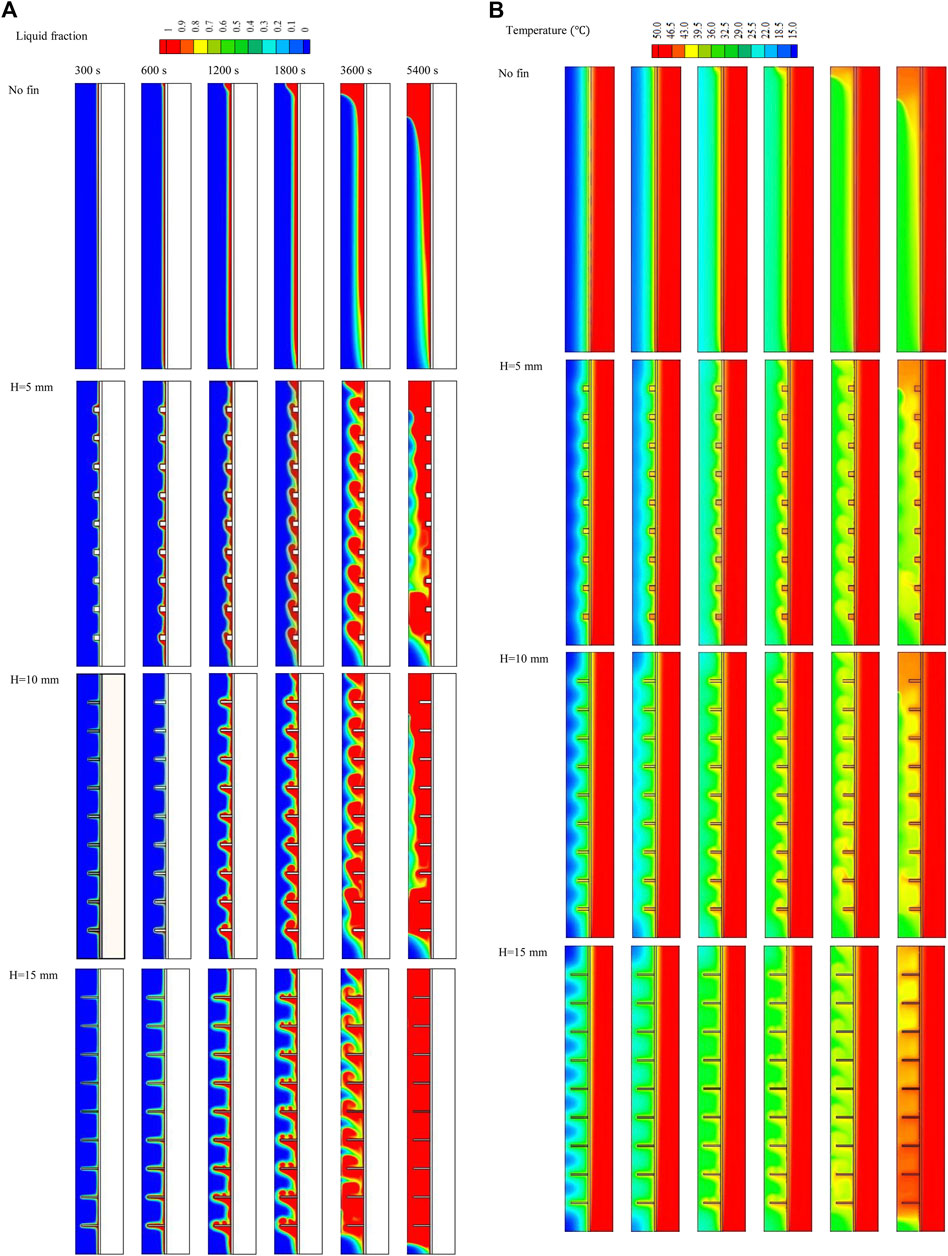
FIGURE 5. (A,B) Liquid fraction (A) and temperature distributions (B) of the PCM with various fin lengths at different times.
The addition of fins enhanced the efficiency of the charging process by enlarging the thermal exchange surface area and increasing the effective conduction heat transfer, as the thermal conductivity of the fins is much higher than that of the PCM. Further, the fins passed the energy from the HTF walls to the deep regions of the PCM domain. Nine fins were added to the heat exchanger wall from the PCM domain side, with a constant distance between them. The second line of Figure 5A shows the system combined with 5-mm-long fins (the shortest fins). The properties of this fin length provide a relatively large area of molten PCM circulation, which improves heat transfer on the one hand but has a lower thermal exchange surface area on the other hand. The PCM started charging alongside the wall and around the fins. The liquefied PCM generated around the fins rose due to the density variation and gathered at the top. Within 5,400 s, the liquid PCM filled the upper part of the domain, and further down into the bottom zone, the thickness of the solid PCM grew at the center of the PCM domain. Increasing the length of the fins to 10 mm expanded the thermal exchange surface area and delivered heat to the deeper zone of the PCM domain. The charging progression behaved like the shorter fins with a larger amount of liquid PCM, and the solid PCM separated into two portions; one sunk to the bottom and the other fluted in the liquid PCM at the center of the domain. Within 5,400 s, 83% of the PCM melted, which increased to 97.7% when using 15-mm-long fins. Even with the most extended fins, the movement of the liquid PCM was relatively limited. However, the largest surface area of the fins and, thus, thermal delivery to the deepest zones of the domain enhance the melting rate.
Figure 5B illustrates the temperature distributions for the cases with various dimensions compared with the finless case. The temperature stayed constant along the channel in the HTF domain due to its short length.The temperature of the PCM rose in the area beside the wall, and the overall temperature rose gradually. Even the PCM melted in the area beside the wall but its temperature remained lower than the HTF temperature and could not reach the thermal equilibrium (50°C) even at 5,400 s, instead achieving 36.4°C at that time. As the fins increase the unit’s thermal efficiency, the PCM temperature was relatively higher than the finless case. For all the fins involved in these cases, the fins themselves could not reach the thermal equilibrium with the HTF even at 5,400 s, as they work as thermal bridges (delivering heat from the fluid to the PCM) and stay lower and higher than the fluid and the PCM. As a result of thermal convection and the buoyancy effect, the liquid PCM, which has a higher temperature, rose to the upper part of the domain. The average temperatures of the domains reached 39°C, 40°C, and 45.5°C for the fin lengths of 5, 10, and 15 mm, respectively. Generally, the mean temperature of the PCM was directly related to fin length due to the broader thermal exchange surface area.
Figure 6A demonstrates the velocity pattern for the previously mentioned cases at 3,600 s. The molten PCM beside the wall rose in the finless case due to the density variation between the solid and liquid phases of natural convection generated during the melting process. The circulation, in this case, had a higher velocity as there was no barrier facing the flow. The addition of fins created a barrier in the flow direction, reducing the velocity and changing the flow’s destination. Increasing the fin length limited the flow’s movement, causing a slower velocity. The fins also caused small swirls in the areas between the fins, which became larger with increased fin length. These behaviors are also shown in Figure 6B, which shows the velocity vectors of the molten PCM in the cases in which fins were added, showing the vortices generated above the fins due to the free convection effect.
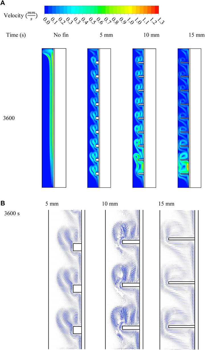
FIGURE 6. Velocity contour (A) and stream factor (B) of the liquid phase of the PCM for various fin lengths at different time steps.
Figure 7A illustrates the progress of the melting process for the cases with different fin lengths and the finless case. Owing to the limited thermal performance, the charging showed a linear behavior, with a gradual melting process for the finless case. The fins increased the system’s thermal responses, causing a sharper rise in the melting line due to the increasing average thermal conductivity and expanding thermal exchange surface area. When 5-mm-long fins were used, the melting slope changed to a lower gradient at 81%, then formed a plateau configuration until total melting occured due to the rule of thermal convection. Owing to the immense heat transfer surface area, the changing point rose to a higher amount of melting, whereas with 10-mm and 15-mm-long fins the gradient changed at 94% and 97%, respectively. The mean temperature increased sharply at the early stage of melting progression because of the thermal conduction generated in the solid-phase PCM (Figure 7B). The increasing heat transfer rate dropped because of the natural convection in the liquefied PCM. The highest temperature was detected for the longest fins due to the large surface area of the heat transfer. Even with total melting, the average temperature of all the systems could not precisely reach thermal equilibrium. By contrast, the average temperature of the PCM for the cases with the fins’ heigth of 15, 10 and 5 mm reached 49.3°C during 129, 189, and 206 mins, respectively; however, the finless case achieved a mean temperature of 49°C at 263 min.
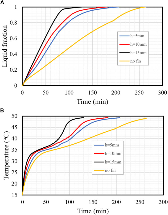
FIGURE 7. (A,B) Progress of the liquid fraction (A) and mean temperature (B) profiles with different fin lengths.
Figure 8A shows the time taken for 95% of the PCM to melt for the previously mentioned cases. The 15-mm-long fins were associated with the shortest melting time, revealing that the system’s heat transfer efficiency improves with increasing fin length. This behavior is produced by the largest thermal exchange surface area of the longest fins on the one hand and the delivery of heat to the deepest region of the PCM on the other hand. The melting time of 95% of the PCM in the best case is 82.45 min, and this time is shorter than the finless case and 5-mm- and 10-mm-long fins by 179%, 75.5%, and 47.3%, respectively. The finless case acts as the worst case because of the limited heat transfer surface area. This conduct is also revealed in the heat recovery rate, which is illustrated in Figure 8B. The heat recovery rate with the longest fins was 32.9 W, which is higher than the finless case and the cases with 5-mm- and 10-mm-long fins by 20.5, 13.2, and 9.7 W, respectively. The summary of this section states that the application of the longest fins enhanced the thermal efficiency of the unit by providing a wider thermal exchange surface area, delivering heat to a deeper zone in the PCM domain and increasing the mean conductive heat transfer of the system.
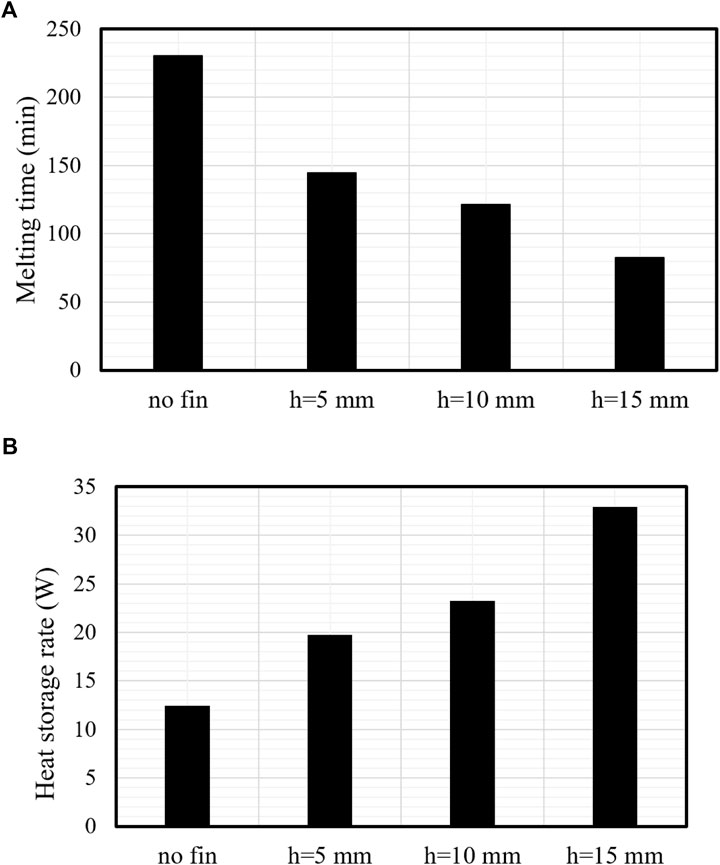
FIGURE 8. (A,B) Charging duration (A) and heat recovery rate (B) of the TES system for different fin lengths compared with no fins.
5.2 Effect of fin number
Figure 9A shows the effect of fin number (4, 9, 15, and 19 fins) on melting performance, assuming a fixed volume of fins for all cases. The charging progression started beside the wall and around the fins and expanded by obtaining more energy from the HTF. The solid PCM separated, creating a solid portion between the neighboring fins, and gradually shrunk over time. The general behavior was the same for all fin numbers, starting with a thin layer of liquid PCM, which gradually expanded until it covered most of the field. Because of the buoyancy effect, the liquid part gathered at the system’s top side, leaving the solid part to sink to the bottom. The application of just four fins in the TES relatively limited the thermal exchange surface area, and only 81% of the PCM melted within 5,400 s; however, this rate increased to 98%, 99.4%, and 100% by raising the number of fins to 9, 15, and 19 fins, respectively. This conduct was caused by the thermal exchange surface area, which increased with the number of fins, while the surface area increased fivefold when the number of fins increased from 4 to 19. The distribution of the fins at a uniform distance also influenced heat distribution in the PCM due to two techniques: First, the thermal exchange occurred more uniformly in the PCM, and second, the upper and lower fins were closer to the highest and lowest sections of the domain. The increase in fin surface area allowed more thermal convection to be transferred to the PCM simultaneously. Owing to the free convection generation, circulation of the liquid PCM occurred; however, the fins acted as a block against this circulation, which confined the natural convection.
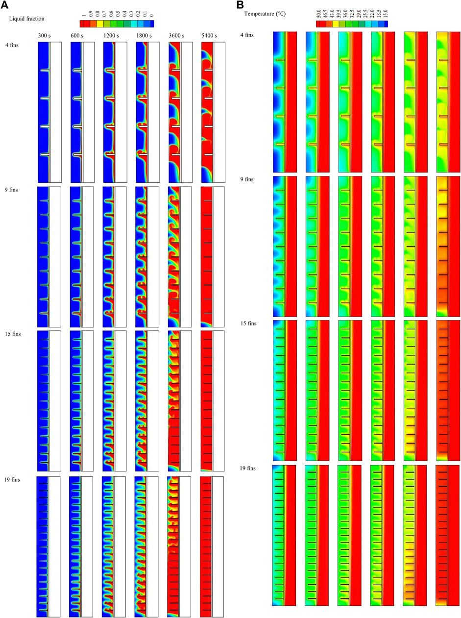
FIGURE 9. (A,B) Liquid fraction (A) and temperature distribution (B) of the liquid phase of the PCM for different fin numbers at different time steps.
The temperature profile contours over 5,400 s with the use of 4, 9, 15, and 19 fins are shown in Figure 9B. Owing to the system’s short length, the HTF’s thermal characteristics remained constant. The PCM’s temperature rose near the wall and the fins. As the fins absorbed energy from the HTF and released it to the PCM, they did not reach thermal equilibrium with it through the entire melting progression in the case with four fins and the early stages in the other cases. For the most recent stages with 15 and 19 fins, the temperature of the fins almost reached a stable condition with the fluid. Owing to its separation from the heat source, the PCM, the system’s central region had the lowest temperature of all the parts. The PCM field gradually approached thermal stability, and because of free convection and density changes, it reached equilibrium more quickly in the top region. When 4, 9, 15, and 19 fins were used separately in the system, the average temperatures of the PCM were 38.4°C, 45°C, 48°C, and 49.5°C. Owing to the domain’s base collecting the solid phase, the temperature there was lower than in other areas. In general, the mean PCM temperature rose as the number of fins increased as more fins provide a larger surface area for thermal exchange, which enhances thermal conduction at the start of the charging process and thermal convection after the generation of the liquid PCM.
The barriers presented by the fins mainly influence the movement of the molten PCM. Increasing the number of fins limits the movement and confines it to the regions between the neighboring fins, as illustrated in Figure 10. At 3,600 s, most of the PCM melted, and movement was observed around the heat recovery system with four fins because of the vast area between the two adjacent fins. The movement in cases with more fins was confined to the limited areas between the fins. However, there was a higher melting rate with a higher number of fins, which predictably should allow higher movement of the liquid PCM.
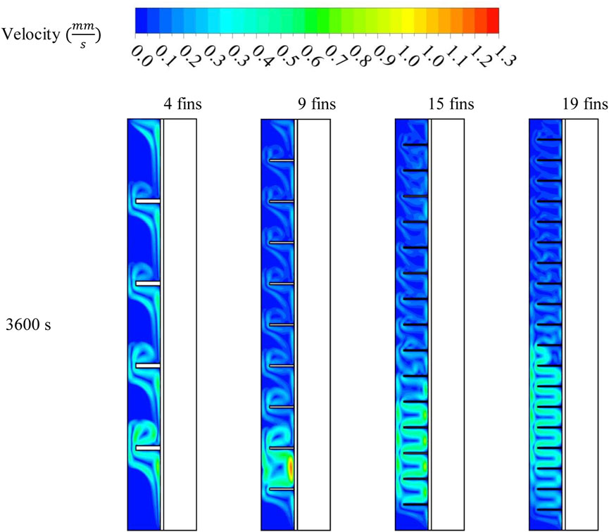
FIGURE 10. The velocity of the liquid phase of the PCM for different fin numbers at 3,600 s.
Figure 11A illustrates the melting progress over time for different fin numbers over 200 min. In every instance, charging variation developed suddenly because of the thermal conduction in the solid segment. Because of the generated thermal convection, the charging slope gradually decreased. When the liquid phase reached more than 90%, the lines became positive in all cases. With four fins, the total melting time was 180 min; however, with 19 fins, the total time for the charging was 78 min, as the higher fin number provided a larger area for heat transfer. The mean temperature increased sharply within the early period due to thermal conduction, as illustrated in Figure 11B. The convection effects created in the liquid PCM near the walls and the fins reduced the heating rate of the PCM. Owing to the wide surface area of the heat transfer with 19 fins, the mean temperature was higher than the other cases at a specific time. The mean temperature with 4, 9, 15, and 19 fins reached 49°C at 180, 127, 93, and 86 min, respectively.

FIGURE 11. (A,B) Liquid fraction (A) and mean temperature (B) with different fin numbers.
The number of the fins affected the charging performance due to changing the surface area and thus the heat delivery rate to the PCM, as shown in Table 2; because of the large surface area and increased thermal rate of the PCM, a high number of fins improved flow time and heat storage rate performance. The system with 19 fins had the lowest melting time (67 min), which was faster than the cases with 4, 9, and 15 fins by 76%, 23%, and 7%, respectively. Further, The heat storage rate was 40.6 W, higher than the cases with 4, 9, and 15 fins by 71%, 23%, and 7.5%, respectively. The delivery of a higher rate of thermal power to the PCM system accelerated the charging procedure and the storage rate. To summarize, more fins provide a larger thermal exchange surface area, resulting in a faster melting progression and a higher heat recovery rate. Table 2 also presents the effect of HTF Reynolds number and temperature, which are studied later.
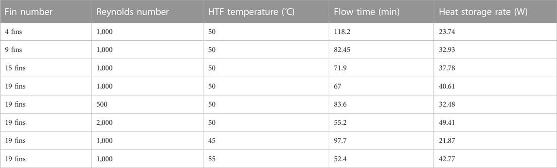
TABLE 2. Impact of fin number, Reynolds number, and HTF temperature on the total charging time and the heat storage rate.
5.3 Effect of the reynolds number
The melting process of the PCM is impacted by the flow rate of the fluid, which is represented by the Reynolds number. The higher flow rate provides the system with continuous warm fluid, which always keeps the temperature differences between the PCM and the fluid as high as possible, helping more energy to pass to the PCM; thus, the PCM melts faster. Three different Reynolds numbers, 500, 1,000, and 1,500, were studied in this paper. It should be noted that based on the dimensions of the system under investigation, in a practical application, a high number of such a system should be used in parallel so that an acceptable amount of heat can be stored. In this way, the fluid with a low flow rate enters the pipe, which is usually placed in a laminar flow regime. The turbulent flow regime can also be investigated in a future study. Figure 12 illustrates the charging procedure of the PCM for scenarios with the longest and highest number of fins for three Reynolds numbers (500, 1,000, and 2,000) at 3,600 s. The figure shows that with a lower Reynolds number, the solid PCM was still confined to the upper part of the domain, whereas the liquid part gathered at the base of the system. An increased Reynolds number increased the melting process, and the solid PCM shrunk more. Most of the PCM (97.8%) melted with a Reynolds number of 2,000, and the only regions still solid were the center and the base of the PCM unit. This conduct is also clarified in Figure 12, which shows that the general temperature profile for the scenario with a higher flow rate was higher than the other two scenarios, and the higher temperature in the domain was concentrated on the bottom side. The system’s mean temperature with a Reynolds number of 2,000 was 44°C.
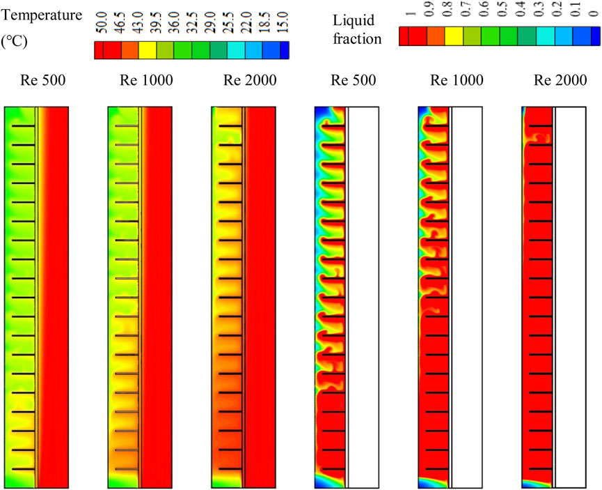
FIGURE 12. The melting process and temperature distribution of the PCM with different Reynolds number (Re) at 3,600 s.
The HTF’s flow rate impacted the thermal energy rate of the PCM and the system’s general performance. This impact, which is represented by various Reynolds numbers (500, 1,000, and 2,000) for 19 fins, is investigated in Figure 13A. The higher flow rate enhanced thermal efficiency and the melting rate. The HTF’s laminar flow rate is represented by low Reynolds numbers selected to utilize a minimum pumping power. The melting behavior lines were nearly identical, with different slopes for different Reynolds numbers. The required time periods for total charging with Reynolds numbers of 500, 1,000, and 2,000 were 101, 90, and 69 min, respectively. Total melting of the PCM was clearly benefitted by the higher Reynolds number as the fastest flow delivered a continuous high temperature to the HTF, resulting in a warmer temperature variance between the HTF and the PCM and producing a larger thermal exchange.
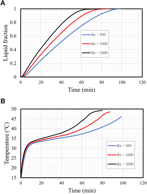
FIGURE 13. (A,B) Liquid fraction (A) and mean temperature (B) of the PCM with different Reynolds numbers (Re) during the charging process.
Figure 13B shows the PCM’s average temperature growth for the above-mentioned Reynolds numbers. The mean average temperature was directly proportional to the Reynolds number as with a high Reynolds number the temperature variance between the HTF and the PCM is high, which increases the thermal exchange in the system. The temperature rose dramatically in the early period of the melting procedure because of the thermally conductive material. Then, the grade reduced due to the rising thermal convection produced by the charging procedure. The difference in the slope of the lines in the figrue, exposed for all Reynolds numbers, initiated at 10 min and was formed by the developing liquid, which created a natural convection impact. Though the variations in the systems’ efficiency were slight when different Reynolds numbers were used, their association with a single factor should be studied so that the whole system’s operation can be enhanced.
Table 2 shows that increases in the Reynolds number from 500 to 1,000 and 2,000 reduced the charging period by 51.6% and 21.6%, respectively, and enhanced the heat storage rate by 52% and 21%, respectively. In summary, a higher flow rate enhances the unit’s operation by reducing the charging period and increasing the storage rate.
5.4 Effect of HTF temperature
The HTF temperature dramatically influenced the phase change process in the TES units. Figure 14 shows the charging procedure of the PCM with different HTF inlet temperatures at 3,600 s. The figure clearly shows that the fluid with the higher temperature helped the PCM melt faster due to the higher thermal rate of the PCM, which results from the higher temperature variance between the PCM and the HTF. With the higher HTF temperature (55°C), more than 99% of the PCM melted, and a tiny part was stuck at the base of the system. When HTF temperature was lowered to 50°C and 45°C the melting rate reduced, and the liquid fraction dropped to 89% and 67%, respectively, at 3,600 s. This behavior is also shown in Figure 14, displays the temperature spreading in the PCM for HTF temperatures of 45°C, 50°C, and 55°C. The average temperature of the PCM was greater (48°C) with a higher initial HTF temperature, and this value reduced to 40°C and 36°C when the HTF’s inlet temperature was 50°C and 45°C.
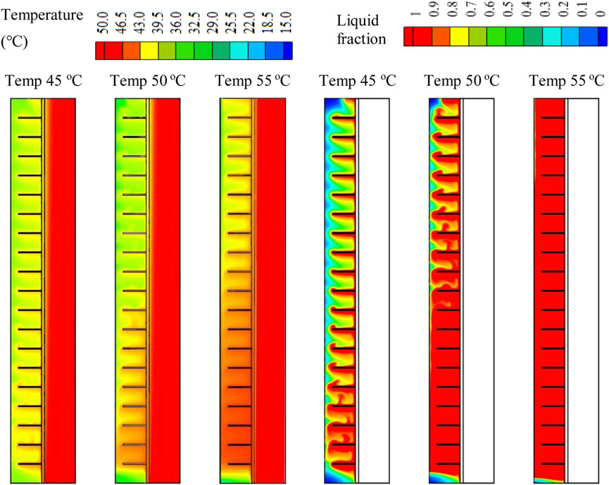
FIGURE 14. The melting process and temperature distribution of the PCM with various HTF inlet temperatures at 3,600 s.
The efficiency of the TES unit was significantly affected by the HTF temperature. Figure 15A illustrates the charging procedures of the TES with three different HTF inlet temperatures (45°C, 50°C, and 55°C). The figure shows that the charging procedure rate was directly related to the HTF temperature. The higher temperature variance between the fluid and the PCM resulted in the more heat exchanged between them. The higher temperature differences caused a higher heat transfer rate, resulting in a faster melting rate. Raising the inlet temperature from 45°C to 50°C and 55°C decreased the charging time by 31 and 54 min, respectively. Higher PCM temperature was achieved using higher HTF temperature, which attained thermal equilibrium more quickly (Figure 15B). The mean temperature of the PCM was 45°C at 55, 76, and 130 min with HTF inlet temperatures of 55°C, 50°C, and 45°C, respectively. This effect was produced by the high temperature differences between the HTF and the PCM, which enhanced the thermal exchange in the system. Table 2 shows the charging time and the average storage rate for the different HTF inlet temperatures when the PCM liquid fraction reached 0.95. The mean temperature of the PCM was 45°C at 55, 76, and 130 min with HTF inlet temperatures of 55°C, 50°C, and 45°C, respectively. This effect was produced by the high temperature differences between the HTF and the PCM, which enhanced the thermal exchange in the system. Table 2 shows the charging time and the average storage rate for the different HTF inlet temperatures. The time required for melting 95% of the PCM was inversely related to the initial temperature of the HTF. The mean temperature of the PCM was 45°C at 55, 76, and 130 min with HTF inlet temperatures of 55°C, 50°C, and 45°C, respectively. This effect was produced by the high temperature differences between the HTF and the PCM, which enhanced the thermal exchange in the system. Table 2 shows the charging time and the average storage rate for the different HTF inlet temperatures. The time required for melting 95% of the PCM was inversely related to the initial temperature of the HTF. Asersely related to the initial temperature of the HTF. As a result, the time required for melting shrunk by 45.7% and 86.6%, and the melting storage rate increased by 10.8 and 20.9 W when the initial temperature rose from 45°C to 50°C and 55°C, respectively.
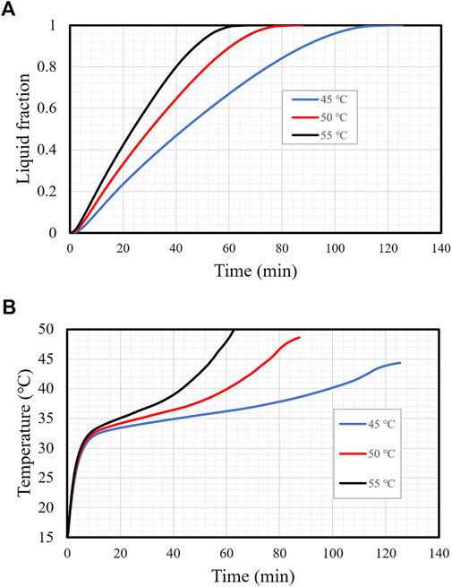
FIGURE 15. (A,B) Liquid fraction (A) and mean temperature (B) variation for different initial HTF temperatures.
6 Conclusion
The central dilemma of the PCM is the limited conductive heat transfer, which negatively effects the phase change rate and the system performance. This issue needs to be solved and then improved to meet the requirement of TES applications. The use of fins in these types of systems improves the average conductive heat transfer of the entire domain, as the thermal conductivity of the fins is much higher than that of the PCM. Rectangular fins with different dimensions and constant sizes were used in this study to resolve the conductive heat transfer of the PCM; these configurations were compared with a finless system. Fin number was also explored, with the application of 4, 9, 15, and 19 fins investigated. The influence of the Reynolds number and thermal fluid temperatures on the charging rate and thermal performance was also investigated. Several computational simulations were run to analyze different configurations and conditions. The valuation of the enhancement included the phases and the temperature dispersals in the domain, charging duration, and heat recovery rate in all cases. The primary outcomes of this work revealed that application of the longest fins recovered the heat transfer efficiency of the system due to the wider thermal exchange surface area, delivering heat to a deeper zone in the PCM domain and increasing the mean thermal conductivity of the system. The melting time for 95% of the PCM with 15-mm-long fins was 82.45 min, which was shorter than with no fins and 5-mm- and 10-mm-long fins by 179%, 75.5%, and 47.3%, respectively. The thermal energy recovery rate with the longest fins was 32.9 W, which was higher than with no fins and 5-mm- and 10-mm-long fins by 20.5, 13.2, and 9.7 W, respectively.
The highest fin number (19) exhibited lower melting time and higher heat storage rate performance because of the wide surface area and enhancement of the thermal rate of the PCM. The system with 19 fins had the lowest melting time (67 min), which was shorter than with 4, 9, and 15 fins by 76%, 23%, and 7%, respectively. Further, the heat storage rate was 40.6 W, which was higher than that of the cases with 4, 9, and 15 fins by 71%, 23%, and 7.5%, respectively. A faster flow velocity improves the system's operation by reducing the charging period and increasing the storage rate. The increase in the Reynolds number from 500 to 1,000 and 2,000 reduced the melting period by 51.6% and 21.6%, respectively, and enhanced the heat storage rate by 52% and 21%, respectively. Further, the time needed to melt 95% of the PCM was inversely a function of working fluid temperature. As a result, the charging time decreased by 45.7% and 86.6% and the melting storage rate grew by 10.8 W and 20.9 W when the inlet temperature rose from 45°C to 50°C and 55°C, respectively.
The principle of applying rectangular fins with different dimensions and in different amounts in TES has not been studied previously. The computational outcomes of this study suggest there is a promising improvement in storage operation when these processes are employed. In addition, further issues, including concerns about the thermal responses and the pressure drop, could be investigated in future studies.
Data availability statement
The original contributions presented in the study are included in the article/supplementary material, further inquiries can be directed to the corresponding authors.
Author contributions
All authors listed have made a substantial, direct, and intellectual contribution to the work and approved it for publication.
Conflict of interest
The authors declare that the research was conducted in the absence of any commercial or financial relationships that could be construed as a potential conflict of interest.
Publisher’s note
All claims expressed in this article are solely those of the authors and do not necessarily represent those of their affiliated organizations, or those of the publisher, the editors and the reviewers. Any product that may be evaluated in this article, or claim that may be made by its manufacturer, is not guaranteed or endorsed by the publisher.
References
Ahmed, S., Abderrahmane, A., Saeed, A. M., Guedri, K., Mourad, A., Younis, O., et al. (2022). Melting enhancement of PCM in a finned tube latent heat thermal energy storage. Sci. Rep. 12, 11521. doi:10.1038/s41598-022-15797-0
Al-Mudhafar, A. H., Nowakowski, A. F., and Nicolleau, F. C. (2021). Enhancing the thermal performance of PCM in a shell and tube latent heat energy storage system by utilizing innovative fins. Energy Rep. 7, 120–126. doi:10.1016/j.egyr.2021.02.034
Chang, H., Han, Z., Li, X., Ma, T., and Wang, Q. (2022). Experimental study on heat transfer performance of sCO2 near pseudo-critical point in airfoil-fin PCHE from viewpoint of average thermal resistance ratio. Int. J. Heat Mass Transf. 196, 123257. doi:10.1016/j.ijheatmasstransfer.2022.123257
Cui, W., Si, T., Li, X., Li, X., Lu, L., Ma, T., et al. (2022). Heat transfer analysis of phase change material composited with metal foam-fin hybrid structure in inclination container by numerical simulation and artificial neural network. Energy Rep. 8, 10203–10218. doi:10.1016/j.egyr.2022.07.178
Ebrahimnataj Tiji, M., Mohammed, H. I., Ibrahem, R. K., Dulaimi, A., Mahdi, J. M., Majdi, H. S., et al. (2022). Evaluation of T-shaped fins with a novel layout for improved melting in a triple-tube heat storage system. Front. Energy Res. 40, 947391. doi:10.3389/fenrg.2022.947391
Eisapour, A. H., Shafaghat, A., Mohammed, H. I., Eisapour, M., Talebizadehsardari, P., Brambilla, A., et al. (2022). A new design to enhance the conductive and convective heat transfer of latent heat thermal energy storage units. Appl. Therm. Eng. 215, 118955. doi:10.1016/j.applthermaleng.2022.118955
Esapour, M., Hosseini, M., Ranjbar, A., Pahamli, Y., and Bahrampoury, R. (2016). Phase change in multi-tube heat exchangers. Renew. Energy 85, 1017–1025. doi:10.1016/j.renene.2015.07.063
Eslami, M., Khosravi, F., and Kohan, H. F. (2021). Effects of fin parameters on performance of latent heat thermal energy storage systems: A comprehensive review. Sustain. Energy Technol. Assessments 47, 101449. doi:10.1016/j.seta.2021.101449
Feng, X., Xia, L., Jiang, Z., Tian, M., Zhang, S., and He, C. (2022). Dramatically promoted toluene destruction over Mn@ Na-Al2O3@ Al monolithic catalysts by Ce incorporation: Oxygen vacancy construction and reaction mechanism. Fuel 326, 125051. doi:10.1016/j.fuel.2022.125051
Ghalambaz, M., Melaibari, A. A., Chamkha, A. J., Younis, O., and Sheremet, M. (2022). Phase change heat transfer and energy storage in a wavy-tube thermal storage unit filled with a nano-enhanced phase change material and metal foams. J. Energy Storage 54, 105277. doi:10.1016/j.est.2022.105277
Guo, Z., Tian, X., Wu, Z., Yang, J., and Wang, Q. (2022). Heat transfer of granular flow around aligned tube bank in moving bed: Experimental study and theoretical prediction by thermal resistance model. Energy Convers. Manag. 257, 115435. doi:10.1016/j.enconman.2022.115435
Hosseini, M., Ranjbar, A., Rahimi, M., and Bahrampoury, R. (2015). Experimental and numerical evaluation of longitudinally finned latent heat thermal storage systems. Energy Build. 99, 263–272. doi:10.1016/j.enbuild.2015.04.045
Huang, P., Yao, L., Gang, Y., Zheng-Xin, L., Yuan-Qing, L., Ning, H., et al. (2021). Graphene film for thermal management: A review. Nano Materials Science 3 (1), 1–16.
Khedher, N. B., Mahdi, J. M., Majdi, H. S., Khosravi, K., Al-Azzawi, W. K., Al-Qrimli, F. A., et al. (2022). CFD analysis of phase-change material-based heat storage with dimple-shaped fins: Evaluation of fin configuration and distribution pattern. J. Comput. Des. Eng. 9, 2055–2072. doi:10.1093/jcde/qwac105
Liu, X., Kang, W., Li, X., Zeng, L., Li, Y., Wang, Q., et al. (2022). Solid-state mechanochemistry advancing two dimensional materials for lithium-ion storage applications: A mini review. Nano Materials Science
Longeon, M., Soupart, A., Fourmigué, J.-F., Bruch, A., and Marty, P. (2013). Experimental and numerical study of annular PCM storage in the presence of natural convection. Appl. Energy 112, 175–184. doi:10.1016/j.apenergy.2013.06.007
Lu, S., Ban, Y., Zhang, X., Yang, B., Yin, L., Liu, S., et al. (2022). Adaptive control of time delay teleoperation system with uncertain dynamics. Front. Neurorobotics 152, 928863. doi:10.3389/fnbot.2022.928863
Ma, X., Sheikholeslami, M., Jafaryar, M., Shafee, A., Nguyen-Thoi, T., and Li, Z. (2020). Solidification inside a clean energy storage unit utilizing phase change material with copper oxide nanoparticles. J. Clean. Prod. 245, 118888. doi:10.1016/j.jclepro.2019.118888
Mabugu, T., and Inglesi-Lotz, R. (2022). The effect of mismatched supply and demand of electricity on economic growth in South Africa. Energy Sources, Part B Econ. Plan. Policy 17, 1–18. doi:10.1080/15567249.2022.2038731
Mahdi, J. M., Lohrasbi, S., and Nsofor, E. C. (2019). Hybrid heat transfer enhancement for latent-heat thermal energy storage systems: A review. Int. J. Heat Mass Transf. 137, 630–649. doi:10.1016/j.ijheatmasstransfer.2019.03.111
Mahdi, J. M., Mohammed, H. I., Talebizadehsardari, P., Ghalambaz, M., Majdi, Sh.H., Khan, A., et al. (2021). Simultaneous and consecutive charging and discharging of a PCM-based domestic air heater with metal foam. Appl. Therm. Eng. 197, 117408. doi:10.1016/j.applthermaleng.2021.117408
Mahdi, J. M., and Nsofor, E. C. (2017a). Melting enhancement in triplex-tube latent heat energy storage system using nanoparticles-metal foam combination. Appl. Energy 191, 22–34. doi:10.1016/j.apenergy.2016.11.036
Mahdi, J. M., and Nsofor, E. C. (2017b). Melting enhancement in triplex-tube latent thermal energy storage system using nanoparticles-fins combination. Int. J. Heat Mass Transf. 109, 417–427. doi:10.1016/j.ijheatmasstransfer.2017.02.016
Mat, S., Al-Abidi, A. A., Sopian, K., Sulaiman, M. Y., and Mohammad, A. T. (2013). Enhance heat transfer for PCM melting in triplex tube with internal–external fins. Energy Convers. Manag. 74, 223–236. doi:10.1016/j.enconman.2013.05.003
Mu, S., Liu, Q., Kidkhunthod, P., Zhou, X., Wang, W., and Tang, Y. (2021). Molecular grafting towards high-fraction active nanodots implanted in N-doped carbon for sodium dual-ion batteries. Natl. Sci. Rev. 8, nwaa178. doi:10.1093/nsr/nwaa178
Najim, F. T., Mohammed, H. I., Al-Najjar, H. M. T., Thangavelu, L., Mahmoud, M. Z., Mahdi, J. M., et al. (2022). Improved melting of latent heat storage using fin arrays with non-uniform dimensions and distinct patterns. Nanomaterials 12, 403. doi:10.3390/nano12030403
Pizzolato, A., Sharma, A., Maute, K., Sciacovelli, A., and Verda, V. (2017). Design of effective fins for fast PCM melting and solidification in shell-and-tube latent heat thermal energy storage through topology optimization. Appl. Energy 208, 210–227. doi:10.1016/j.apenergy.2017.10.050
Said, Z., Zeyad, H., Eisa, T. I., and Assad, M. E. H. March 2019. "Nano-enhanced PCM for energy storage", in: Proceedings of the 2019 Advances in Science and Engineering Technology International Conferences (ASET), 1–6. Dubai, UAE.
Sardari, P. T., Mohammed, H. I., Giddings, D., Walker, G. S., Gillott, M., and Grant, D. (2019). Numerical study of a multiple-segment metal foam-PCM latent heat storage unit: Effect of porosity, pore density and location of heat source. Energy 189, 116108. doi:10.1016/j.energy.2019.116108
Shahsavar, A., Shaham, A., and Talebizadehsardari, P. (2019). Wavy channels triple-tube LHS unit with sinusoidal variable wavelength in charging/discharging mechanism. Int. Commun. Heat Mass Transf. 107, 93–105. doi:10.1016/j.icheatmasstransfer.2019.05.012
Smith, R., Ebersole, T., and Griffin, F. (1980). Heat exchanger performance in latent heat thermal energy storage. Energy Convers. Manag. 31.
Sohani, A., Shahverdian, M. H., Hoseinzadeh, S., and El Haj Assad, M. (2023). “7 - thermal energy storage systems,” in Emerging trends in energy storage systems and industrial applications. Editor Prabhansu & N. Kumar (Cambridge, MA, USA: Academic Press), 189–222.
Talebizadehsardari, P., Mahdi, J. M., Mohammed, H. I., Moghimi, M., Eisapour, A. H., and Ghalambaz, M. (2021). Consecutive charging and discharging of a PCM-based plate heat exchanger with zigzag configuration. Appl. Therm. Eng. 193, 116970. doi:10.1016/j.applthermaleng.2021.116970
Wang, P., Wang, X., Huang, Y., Li, C., Peng, Z., and Ding, Y. (2015). Thermal energy charging behaviour of a heat exchange device with a zigzag plate configuration containing multi-phase-change-materials (m-PCMs). Appl. energy 142, 328–336. doi:10.1016/j.apenergy.2014.12.050
Wen, Q., He, X., Lu, Z., Streiter, R., and Otto, T. (2021). A comprehensive review of miniatured wind energy harvesters. Nano Materials Science 3 (2), 170–185.
Ye, W.-B., Zhu, D.-S., and Wang, N. (2011). Numerical simulation on phase-change thermal storage/release in a plate-fin unit. Appl. Therm. Eng. 31, 3871–3884. doi:10.1016/j.applthermaleng.2011.07.035
Zhang, N., Yuan, Y., Cao, X., Du, Y., Zhang, Z., and Gui, Y. (2018). Latent heat thermal energy storage systems with solid–liquid phase change materials: A review. Adv. Eng. Mater. 20, 1700753. doi:10.1002/adem.201700753
Zhang, X., Tang, Y., Zhang, F., and Lee, C. S. (2016). A novel aluminum–graphite dualion battery. Adv. energy Mater. 6, 1502588. doi:10.1002/aenm.201502588
Zhou, N., Price, L., Yande, D., Creyts, J., Khanna, N., Fridley, D., et al. (2019). A roadmap for China to peak carbon dioxide emissions and achieve a 20% share of non-fossil fuels in primary energy by 2030. Appl. Energy 239, 793–819. doi:10.1016/j.apenergy.2019.01.154
Nomenclature
E (J) heat storage
Greek symbols
Abbreviations
TES thermal energy storage
PCM phase change materials
LHS latent heat storage
HTF heat transfer fluid
Re reynolds number
LHTES latent heat thermal energy storage
TTHX triple-tube heat exchanger
Keywords: double-tube latent thermal storage, pcm, optimal fin design, melting process melting, phase change materials, thermal energy storage, heat transfer enhancement, arcshaped fins
Citation: Shojaeinasab Chatroudi I, Atashafrooz M, Mohammed HI, Abed AM and Talebizadehsardari P (2023) Heat transfer enhancement and free convection assessment in a double-tube latent heat storage unit equipped with optimally spaced circular fins: Evaluation of the melting process. Front. Energy Res. 11:1097382. doi: 10.3389/fenrg.2023.1097382
Received: 13 November 2022; Accepted: 04 January 2023;
Published: 23 January 2023.
Edited by:
Feng Jiang, Nanjing Tech University, ChinaReviewed by:
Binjian Nie, University of Oxford, United KingdomMamdouh El Haj Assad, University of Sharjah, United Arab Emirates
Copyright © 2023 Shojaeinasab Chatroudi, Atashafrooz, Mohammed, Abed and Talebizadehsardari. This is an open-access article distributed under the terms of the Creative Commons Attribution License (CC BY). The use, distribution or reproduction in other forums is permitted, provided the original author(s) and the copyright owner(s) are credited and that the original publication in this journal is cited, in accordance with accepted academic practice. No use, distribution or reproduction is permitted which does not comply with these terms.
*Correspondence: Pouyan Talebizadehsardari, cG91eWFuLnRhbGViaXphZGVoc2FyZGFyaUBicnVuZWwuYWMudWs=