 Chao Fang
 Xingjie Peng
 Chen Zhao
 Lei Lou
 Bin Zhang
 Lianjie Wang*
- Science and Technology on Reactor System Design Technology Laboratory, Nuclear Power Institute of China, Chengdu, China
The full-core neutronics/thermal-hydraulics (NE/TH) coupling analysis for a small lead-based fast reactor (SLFR) was presented. The NE-to-TH coupling occurs via power distribution, whereas the TH-to-NE coupling occurs via the material cross section, which is related to the temperature distribution. In the NE module, a discrete ordinate (SN) nodal solver is implemented based on the hexagonal prism mesh. In the TH module, a parallel channel model is implemented with each hexagonal fuel assembly as a channel. The mass flow of each channel is searched according to the same pressure drop, the temperature and density of the coolant within each channel is calculated with a one-dimensional axial heat convection model, and the temperature distribution along the fuel pin is calculated with a one-dimensional radial heat conduction model. In order to update the cross section, a temperature-dependent homogenized microscopic cross-section library is prepared in advance, and based on the temperature distribution obtained from the TH calculation, the cross-section data required by the NE calculation are obtained by interpolation. The results of the NE/TH coupling analysis for SLFR indicate that the TH parameters (the maximum temperature of the fuel, cladding, and coolant and the maximum velocity of the coolant) are all within the design limits, and the TH feedback provides negative reactivity feedback (about −200 pcm) and has a fairly small effect on the power distribution (<1.0%).
1 Introduction
Climate change caused by excessive greenhouse gas emission has become a major challenge for mankind; carbon neutrality and low-carbon energy transformation are becoming the long-term development visions of all countries around the word, which provides opportunities for the development of clean and low-carbon energy, including nuclear energy.
The innovation of nuclear energy technology is getting more and more attention among the world’s nuclear powers, the development of advanced Generation IV (Pioro, 2016) reactors is accelerating, and fast reactors are the dominant route because of significant advantages in terms of fuel utilization and nuclear non-proliferation (Cochran et al., 2010). In order to supply power for remote isolated areas and other special fields, miniaturization and modularization (Wang et al., 2015; Wu et al., 2016) have become important directions of reactor development. Lead-based alloys, including lead and lead-bismuth eutectic (LBE) (Concetta, 2015), are good choices as coolants for small fast reactors, owing to their good neutronic characteristics, high thermal conductivity, and strong natural circulation capability. These advantages can simplify the system design and make the reactor more compact and reliable.
Numerical simulation is the basis of reactor design, safety analysis, and optimization (YANG WS, 2012). A nuclear reactor is a complex multi-physical coupling system (Christophe, 2020), which includes neutronics, thermal-hydraulics, mechanicals, materials, and chemistry. Among them, the coupling between neutronics and thermal-hydraulics is relatively strong, and coupled numerical simulation of NE/TH is of great importance in the design stage of a nuclear reactor core.
The purpose of neutronics calculation is to obtain the effective multiplication factor (keff) and power distribution, which provide the heat source to the thermal-hydraulics calculation. The most high-fidelity option is to use the Monte Carlo (MC) method, but it has low efficiency, and the mesh mapping between neutronics and thermal-hydraulics is complicated. The most efficient option is to use the traditional few-group diffusion method, but for SLFR, due to the strong leakage and anisotropy of fast neutrons and complex energy spectrum, this method will lead to large calculation error of flux and keff. The discrete ordinates (SN) nodal method can balance the calculation accuracy and efficiency well. Due to the fact that the average free path of fast neutrons tends to reach one assembly width, it is not necessary to subdivide the assembly into smaller meshes; the nodal can use the hexagonal prism mesh directly.
The purpose of thermal-hydraulics calculation is to obtain the temperature distribution of the fuel, cladding, and coolant and the velocity and density distribution of coolant, which provide parameters to feedback on and design the reactor. The most high-fidelity option is to use the computational fluid dynamics (CFD) method, but it also has low computational efficiency. In this work, a parallel channel model is implemented. Due to the fact that typical assemblies of SLFR are canned, this model assumes each hexagonal fuel assembly as a channel and there is no mass, momentum, and energy exchange between the channels, which implies a uniform distribution of different (NE and TH) relevant parameters at the assembly level. A 1D axial heat convection model is developed to calculate coolant temperatures within each flow channel. The heat source of the assembly is distributed to each fuel rod equally, and a 1D radial heat conduction model is developed to obtain the temperature distribution of the fuel and cladding. The mass flow and velocity of coolants are calculated by iterative research studies to ensure the same pressure drop in each channel.
The NE/TH coupling solution strategies (Wang, Wang and Ding, 2020a) can be divided into tight coupling and loose coupling. Tight coupling refers to solving the NE and TH simultaneously, while loose coupling means to solve them separately, and coupling is realized by exchanging data between them. Loose coupling can be further divided into internal and external couplings. Internal coupling refers to exchange data through memory, while external coupling means transfer data through input and output files. In this work, a loose internal coupling strategy is adopted to achieve the NE/TH coupling. The Picard iteration method is used to transfer the coupling parameters, and the data exchange is repeated until both the NE and TH fields have converged.
This paper is organized as follows: Section 2 introduces the neutronics model, derives the SN nodal method in detail, and obtains the nodal response relation with the hexagonal prism nodal by transverse integral technology and nodal equivalence finite difference (NEFD) method (Wang et al., 2020). Section 3 introduces the thermal-hydraulics model and derives the parallel channel method, which include the 1D axial heat convection model, flow rate distribution model, and 1D radial heat conduction model. Section 4 describes the cross-section update model and coupling calculation process. Section 5 presents the NE/TH coupling analysis for a native designed small lead-based fast reactor (SLBR) (Zhao et al., 2022, p. 50). Finally, the study is summarized and some conclusions are drawn in Section 6.
2 Neutronics model
Considering the balance of calculation accuracy and efficiency, the SN nodal method with the hexagonal prism mesh is adopted in the neutronics model. This method decouples the 3-dimensional problem into four 1-dimensional problems, using the weighted orthogonal polynomials to expand the unknowns as test functions to do the Galerkin projection. The nodal response relation is obtained by the nodal equivalence finite difference (NEFD) method, and then, the equation can be solved by sweeping to improve the computational efficiency. The detail theory model is as follows.
2.1 Neutron transport equations
The steady-state neutron transport equation can be written as follows:
where
Multi-group approximation is adopted for energy, and the discrete ordinate method is adopted for angular discretization. After that, a single group neutron transport equation in each direction can be obtained.
where m represents the direction index, g represents the energy group index, and
Ignoring m and g indexes, the transport equation for the hexagonal prism in the calculated coordinate system (Figure 1) can be written as
where
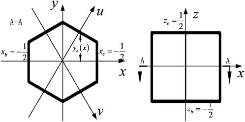
FIGURE 1. Hexagonal prism in the calculated coordinate system.
2.2 Transverse integral
Three-dimensional transport equations can be decoupled into three radial and one axial equation by transverse integral technique. Integral Eq. 3 within
Let
Then, the outgoing integral flux can be obtained as
Similar equations can be obtained for the direction of u, v, and z.
2.3 Polynomial expansion
The transverse integral flux, source, and axial leakage term can be expanded by orthogonal polynomials with weights as
The first three order polynomials are defined as follows:
We insert Eq. 7 and Eqs 8–5, then multiply both sides of the equation by the basis function, and integrate over the nodal, so the nodal response relationship can be obtained. We insert Eq. 7 and Eqs 8–6, and the relationship of the outgoing surface flux with the incoming surface flux can be obtained.
2.4 Nodal response relation
In hexagonal prism geometry, for any given direction of the quadrature with 60° symmetry, there are three radial planes, one axial plane as the incoming plane, and the remaining planes as the outgoing planes. The response relationship of the outgoing surface flux with the nodal average flux and incoming surface flux can be expressed as
where the coefficients and derivation process can be referred to Wang et al. (2020. Integrating Eq. 3 within a nodal, the neutron balance equation can be obtained.
where
According to the sweeping order determined in advance, the average flux of the nodal is calculated by Eq. 12 with incoming boundary condition, and then, the outgoing surface flux is calculated by Eq. 10 and taken as the incoming boundary condition of the next nodal. The flux distribution and keff are obtained by iterative of the nodal, direction, and energy group, and then, the power distribution can be obtained as
where
3 Thermal-hydraulics model
Due to the typical assemblies of SLFR being canned, a parallel channel model (Teng-Yue et al., 2015) is implemented for the TH calculation, and this model assumes each hexagonal fuel assembly as a channel with no mass, momentum, or energy exchange between channels. The first step of this model is to search the flow rate of each coolant channel according to the same pressure drop of each inlet and outlet, in which the pressure drop is obtained by solving axial 1D momentum conservation equations, and then, the axial coolant temperature distribution of each channel is calculated by the 1D axial heat convection model. Finally, the temperature distribution of the fuel and cladding is calculated by the 1D radial heat conduction model.
3.1 Axial heat convection model
3.1.1 Conservation equations
The conservation equations of the 1D single-channel model can be expressed as follows.
Mass conservation equation:
Momentum conservation equation:
Energy conservation equation:
where
It can be assumed that all enthalpy rises are converted into coolant temperature rises, thus the average temperature rises of the coolant within a nodal can be calculated as
where
The heat transfer between the cladding surface and the coolant is mainly single-phase convection, thus the cladding surface temperature can be calculated as
where
3.1.2 Flow rate distribution model
For the parallel channel model, the pressure drop of each channel is a function of the mass flow rate and is equal, which can be expressed as
The first-order Taylor expansion can be performed on the pressure drop function as
where
Thus, the mass flow rate can be updated with the following formula:
The diagrammatic drawing of the parallel channel model is shown in Figure 2.
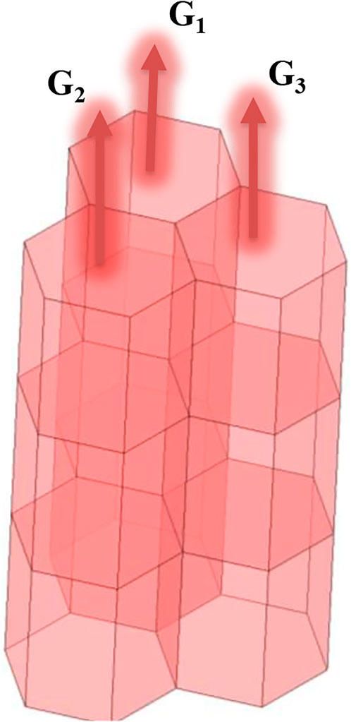
FIGURE 2. Parallel channel model.
The calculation process of the flow distribution and coolant temperature distribution can be summarized as follows:
(1) Initial flow rate distribution is determined based on the flow area of each channel.
(2) The temperature distribution and pressure drop of each channel are obtained by solving the conservation equations.
(3) If the pressure drops of all channels are the same, end the calculation. Otherwise, redistribute the flow rate and go to step (2).
3.2 Radial heat conduction model
In the steady state and ignoring the axial heat transfer, the heat transfer equation and boundary condition in the cylindrical coordinate system are as follows:
where
Integrating the equation over the space, the following equation can be obtained:
The finite difference method (FDM) is used to solve Eq. (27).The fuel is divided into more than five segments, the gap is one segment, and the cladding is at least two segments (as shown in Figure 3). The radial temperature distribution of the fuel pin can be obtained by solving the linear equations generated by FDM.
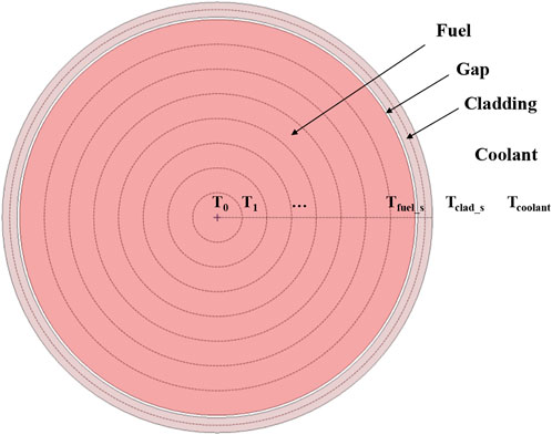
FIGURE 3. Fuel pin temperature calculation model.
4 Neutronics/thermal-hydraulics coupling model
A loose internal coupling strategy is adopted to do the NE/TH coupling calculation. The NE-to-TH coupling via power distribution can be transferred directly through the memory, whereas the TH-to-NE coupling via the temperature-dependent material cross sections can be calculated by interpolating within temperature-dependent cross-section tables.
4.1 Cross-section update
The temperature-dependent cross-section library is generated by the external program, which uses 1D cylindrical geometry to equivalent the hexagonal assembly, superfine group method to do the resonance calculation, and super homogenization (SPH) method to do cross-section homogenization. Once the cross-section library of the fuel, cladding, and coolant at tabulated temperature is generated, the cross section at any temperature can be obtained by interpolation. The linear interpolation formula is as follows:
where
For cladding and coolant materials, the cross sections are linearly interpolated by temperature. Thus,
Based on the temperature distribution obtained from the TH calculation, the cross section data required by the NE calculation can be obtained.
The macroscopic cross section is related to the microscopic cross section and density of nuclides, both of which vary with temperature. The microscopic cross section can be obtained by interpolation described previously, while the variation in the nuclide density with temperature is mainly due to the variation in material density. Assuming that the material density at temperature
where
4.2 Coupling calculation process
The NE/TH coupling calculation process can be divided into four parts. First, the homogeneous microscopic cross-section library of the hexagonal assembly at different state points is obtained by the assembly calculation. Then, the cross section is interpolated according to the temperature distribution (taking the design temperature for the first calculation) to obtain the cross section at the actual state point. Next, neutronics calculation is carried out to obtain the power distribution. Finally, the power distribution is set as the heat source for TH calculation and the temperature distribution of the fuel, cladding, and coolant in the reactor core is obtained. The calculation and data transfer process are shown in Figure 4. The Picard iteration method is adopted to do the NE/TH coupling calculation, which keeps iterating until the NE fields and TH fields have converged.
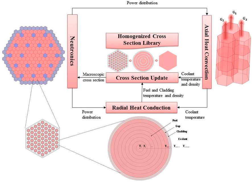
FIGURE 4. NE/TH coupling calculation process.
5 Coupling analysis for a small lead-based fast reactor
In this section, the NE/TH coupling analysis for a native designed small lead-based fast reactor (SLBR) is presented.
5.1 Model description
The thermal power of the reactor is 50 MW, the material of the fuel is 19.95% enrichment UO2, the control-rod absorber material is B4C, the reflector material is BeO, and the coolant material is the lead-bismuth eutectic (LBE) (44.5% Pb and 55.5% Bi). The reactor core consists of 144 fuel assemblies, 18 control-rod assemblies, and 48 reflector assemblies, each assembly consists of 61 rods, which are arranged in a triangular grid, and the configuration is shown in Figure 5. The detailed core parameters can be found in the work of Zhao et al. (2022, p. 50).

FIGURE 5. SLBR-50 configuration.
5.2 Physical parameters
The physical properties of the materials in SLBR refer to Sobolev, (2007) and Roelofs, (2019), and the thermal conductivity of fuel material varies with temperature as
The thermal conductivity of cladding materials varies with temperature as
The melting point of the LBE coolant is 397 K and the boiling point is 1943 K. When using liquid metals as coolants and the fuel rods are arranged in triangular grids with
where Pe is the Peclet number, Re is the Reynolds number, and Pr is the Prandtl number. The heat transfer coefficient of LBE can be obtained by the Nusselt number. To avoid corrosion of the cladding by the liquid metal coolant, the velocity of LBE should not exceed 2 m/s.
5.3 Result analysis
When making the cross section library, the selected temperature points should cover all working states, thus, the microscopic cross sections at 600, 700, 800, 1000, and 1200 K are made for fuel, cladding, and coolant materials. For the NE calculation, the order of discrete ordinates is set at S6, the radial mesh is used to create hexagonal assembly, and the axial mesh is 5 cm per layer. For the TH calculation, only fuel assemblies are considered, the axial mesh is computed using the NE calculation, the radial mesh is divided into five segments for fuel, one segment for gap, and two segments for cladding. The power distribution result is shown in Figure 6.

FIGURE 6. Power distribution.
The maximum power location is at the central fuel assembly, and the fuel–rod temperature distribution at the central assembly is shown in Figure 7. The maximum temperature of the fuel, cladding, and coolant is all presented in this assembly, which is shown in Table 1.
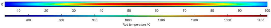
FIGURE 7. Temperature distribution of the fuel rod in the central assembly.
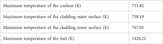
TABLE 1. Maximum temperature of different material regions.
Figures 8, 9, 10, 11, 12 show the average fuel temperature, coolant temperature, coolant density, coolant flow rate, and coolant velocity distribution, which are outputted with the hexagonal nodal mesh, respectively. It can be seen that the average temperature distribution of the fuel is similar to the power distribution, and the maximum average temperature of the fuel is less than 1200 K. Since the single-channel model is applied to each parallel channels, the coolant temperature presents a one-dimensional distribution, the density of the coolant changes very little, and its distribution is the opposite of the temperature distribution. The flow rate and velocity distribution are similar to the two-dimensional power distribution, the maximum velocity is equal to 1.8 m/s, which is less than the limit 2 m/s.
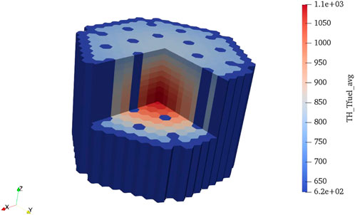
FIGURE 8. Average temperature distribution of the fuel.
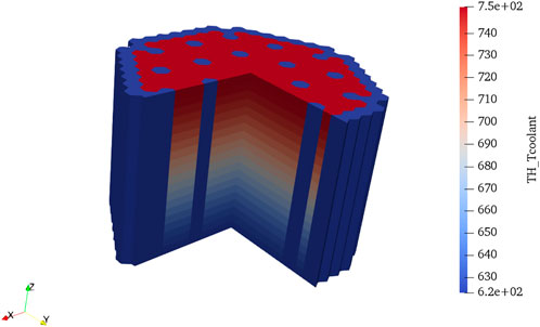
FIGURE 9. Temperature distribution of the coolant.
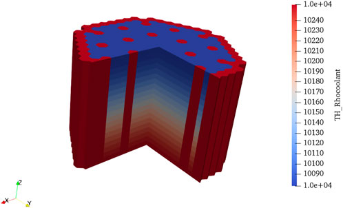
FIGURE 10. Density distribution of the coolant.

FIGURE 11. Flow rate distribution of the coolant.
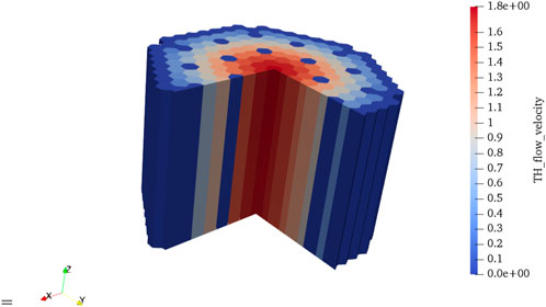
FIGURE 12. Velocity distribution of the coolant.
The NE/TH coupling calculation converges after two iterations, and the results of neutronics parameters with and without the TH feedback are shown in Table 2. As we can see, whether TH feedback is considered has little influence on the results of the NE calculation. After considering TH feedback, the effective multiplication factor is reduced by 207 pcm, and the axial and radial power peak factors have small changes. Figure 13 compares the axial power distribution between with TH feedback and without TH feedback and the power distribution almost stays the same. It can be considered that, in steady-state calculation of the fast reactor, the TH calculation has little influence on the NE calculation, and TH feedback calculation is generally not required.
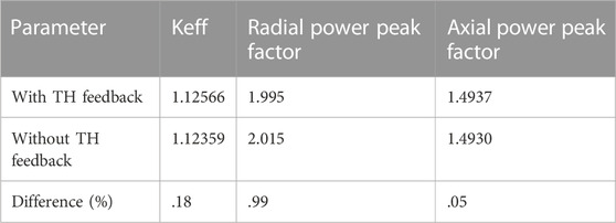
TABLE 2. Comparison of neutronics parameters with and without TH feedback.
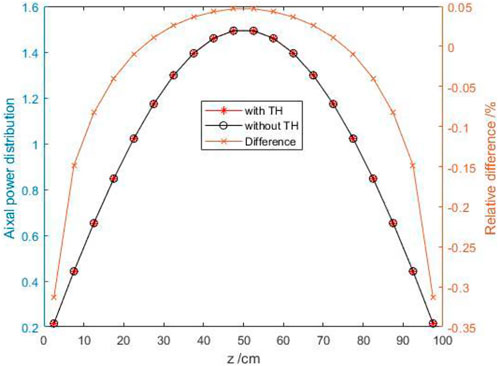
FIGURE 13. Compare axial power distribution between with TH and without TH calculation.
6 Conclusion
A neutronics and thermal-hydraulics loose internal coupling code system was developed in this paper, where the neutronics calculation was based on the SN nodal method with the hexagonal prism mesh, and the thermal-hydraulics calculation was based on the parallel channel model. The neutron flux, the temperature distribution of the fuel, cladding, and coolant, and the velocity, density, and pressure distribution of the coolant in each hexagonal nodal can be obtained through this code system.
Application of the code system could be used for steady-state neutronics thermal-hydraulics coupling analysis for a conceptually designedsmall lead-based fast reactor (SLFR-50). The power distribution and thermal-hydraulics parameters are analyzed, which show that the maximum temperature of the fuel, cladding, coolant, and the maximum velocity of the coolant are all within the design limits. The coupling calculation converges rapidly and the thermal-hydraulics feedback provides negative reactivity feedback (about −200 pcm) and has a fairly small effect on the power distribution (<1.0%).
The results of the NE/TH coupling analysis for SLFR-50 show that the thermal-hydraulics feedback has a fairly small effect on the effective multiplication factor and power distribution; it can be reasonably believed that the power distribution obtained by neutronics calculation can be directly used in the thermal-hydraulics calculation for metal-cooled fast spectrum reactors and the iterative calculation is not required. Theoretically, one reason for this phenomenon is that the number of neutrons in the resonance energy group for fast spectrum reactors is much less than that of thermal spectrum reactors. The Doppler effect has little effect on the neutronics calculation results, and another reason is that the small gradients of temperature distribution and little changes of material density make the macroscopic cross section change a little. The dimensional changes with temperature will have a great impact on the neutronics results for the fast reactor, which needs to be considered for more accurate simulation.
In the future, the neutronics thermal-hydraulics and thermal-mechanic coupling analyses for the fast spectrum reactor will be studied, and the effects of thermal-hydraulics feedback on the neutronics calculation with different energy spectrums will be compared. Experimental studies will be used to validate this code system.
Data availability statement
The original contributions presented in the study are included in the article/Supplementary Material; further inquiries can be directed to the corresponding authors.
Author contributions
CF: main research and manuscript writing. CZ, LL, and BZ: research. XP, LW, ZC, and QL: advice and directing.
Funding
This work was financially supported by the China Association for Science and Technology (Young Elite Scientists Sponsorship Program 2019QNRC001).
Conflict of interest
The authors declare that the research was conducted in the absence of any commercial or financial relationships that could be construed as a potential conflict of interest.
Publisher’s note
All claims expressed in this article are solely those of the authors and do not necessarily represent those of their affiliated organizations, or those of the publisher, the editors, and the reviewers. Any product that may be evaluated in this article, or claim that may be made by its manufacturer, is not guaranteed or endorsed by the publisher.
References
Christophe, D. (2020). Modelling of nuclear reactor multi-physics: From local balance equations to macroscopic models in neutronics and thermal-hydraulics. Cambridge, United States: Academic Press.
Cochran, T. B., Feiveson, H. A., Patterson, W., Pshakin, G., Ramana, M. V., Schneider, M., et al. (2010). ‘Fast breeder reactor programs: History and status’. International Panel on Fissile Materials. Paris, France: OECD, 128.
Concetta, F. (2015). Handbook on lead-bismuth eutectic alloy and lead properties, materials compatibility, thermal-hydraulics and technologies. Accessed Available at: http://publications.jrc.ec.europa.eu/repository/handle/JRC100764 November 1, 2022).
Mikityuk, K. (2009). Heat transfer to liquid metal: Review of data and correlations for tube bundles. Nuclear Engineering and Design. 239 (4), 680–687. doi:10.1016/j.nucengdes.2008.12.014
Pioro, I. L. (2016). “Handbook of generation IV nuclear reactors,” in Handbook of generation IV nuclear reactors. Editor Igor L. Pioro (Sawston, United Kingdom: Woodhead Publishing (Woodhead Publishing Series in Energy), 37–54.
Roelofs, F. (2019). Thermal hydraulics aspects of liquid metal cooled nuclear reactors. Sawston, United Kingdom: Woodhead Publishing.
Sobolev, V. (2007). Thermophysical properties of lead and lead–bismuth eutectic. Journal of Nuclear Materials. 362 (2), 235–247. doi:10.1016/j.jnucmat.2007.01.144
Teng-Yue, M. A., (2015). ‘Neutronics and thermal-hydraulics coupled calculation for ADS based on single-channel model’. Atomic Energy Science Technology 49, 604–608. [Preprint] Available at: http://en.cnki.com.cn/Article_en/CJFDTOTAL-YZJS201504005.htm (Accessed November 1, 2022).
Wang, J., Wang, Q., and Ding, M. (2020a). Review on neutronic/thermal-hydraulic coupling simulation methods for nuclear reactor analysis. Annals of Nuclear Energy 137, 107165. doi:10.1016/j.anucene.2019.107165
Wang, M., Lian, C., Li, Y., Wang, D., Jiang, J., and Wu, Y. (2015). Preliminary conceptual design of a lead–bismuth cooled small reactor (CLEAR-SR). International Journal of Hydrogen Energy 40 (44), 15132–15136. doi:10.1016/j.ijhydene.2015.03.097
Wang, Y., Xu, Z., Zheng, Y., and Wu, H. (2020b). A new hexagonal-Z nodal SN method in SARAX code system. Annals of Nuclear Energy 144, 107546. doi:10.1016/j.anucene.2020.107546
Wu, Y., Bai, Y., Song, Y., Huang, Q., Zhao, Z., and Hu, L. (2016). Development strategy and conceptual design of China lead-based research reactor. Annals of Nuclear Energy 87, 511–516. doi:10.1016/j.anucene.2015.08.015
Yang, W. S. (2012). ‘Fast reactor physics and computational methods’, Nuclear engineering and technology. International Jornal of Korean Nuclear Society 44 (2), 177–198. doi:10.5516/net.01.2012.504
Keywords: small lead-based fast reactor, neutronics/thermal-hydraulics coupling, discrete ordinate method, hexagonal prism nodal method, parallel channel method
Citation: Fang C, Peng X, Zhao C, Lou L, Zhang B, Wang L, Chen Z and Li Q (2023) Neutronics and thermal-hydraulics coupling analysis for a small lead-based fast reactor based on the discrete ordinate nodal and parallel channel method. Front. Energy Res. 11:1088718. doi: 10.3389/fenrg.2023.1088718
Received: 03 November 2022; Accepted: 02 January 2023;
Published: 13 January 2023.
Edited by:
Turgay Korkut, Sinop University, TürkiyeReviewed by:
Pavel Tsvetkov, Texas A&M University, United StatesHaochun Zhang, Harbin Institute of Technology, China
Copyright © 2023 Fang, Peng, Zhao, Lou, Zhang, Wang, Chen and Li. This is an open-access article distributed under the terms of the Creative Commons Attribution License (CC BY). The use, distribution or reproduction in other forums is permitted, provided the original author(s) and the copyright owner(s) are credited and that the original publication in this journal is cited, in accordance with accepted academic practice. No use, distribution or reproduction is permitted which does not comply with these terms.
*Correspondence: Xingjie Peng, cGVuZ3hpbmdqaWV0c0AxMjYuY29t; Lianjie Wang, d2FuZ2xpYW5qaWVAdHNpbmdodWEub3JnLmNu