 Izabela Gutowska
 Brian G. Woods
 Joshua Halsted
- School of Nuclear Science and Engineering, Oregon State University, Corvallis, OR, United States
Among the Next-Generation Nuclear Plant (NGNP) designs, the High-Temperature Gas-Cooled Reactors (HTGRs) are very attractive, due to their inherent safety features, high power conversion efficiency, and potential of providing high-temperature process heat. To perform a thorough safety study and to license these types of reactors, sufficient information needs to be provided about the phenomena that occur during accident scenarios. While several experimental research efforts have been dedicated in the past to investigate accident scenarios, knowledge gaps still exist in the phenomena characteristic of pressurized and depressurized conduction cooldown (PCC/DCC) transients as well as for normal operation scenarios. This paper summarizes the Oregon State University High Temperature Test Facility (HTTF) test matrix, experimental campaign, and selected tests results. High Temperature Test Facility is a scaled Integral Test Facility (IET) that is capable of mimicking scaled dimensions and operational conditions of the Modular High-Temperature Gas Cooled Reactor (MHTGR). The goal of the High Temperature Test Facility is to provide experimental data on the DCC, PCC and normal operating scenarios of the reference Modular High-Temperature Gas Cooled Reactor design. The DCC, PCC, mixing, heat up and cooldown tests described in this paper were performed at prototypical Modular High-Temperature Gas Cooled Reactor temperatures, scaled initial pressure conditions (∼200 kPa), and thermal power input of less than 70 kW. Presented test data show temperature distributions in the High Temperature Test Facility core, upper plenum, cross duct, or lower plenum. Based on these temperature profiles attempts to investigate stratified flow, natural convection flow, heat up, cooldown and mixing phenomena are made. Furthermore, this paper evaluates the performed test campaign in the light of the Very High Temperature Gas-cooled Reactor Phenomena Identification and Ranking Table (PIRT) and proposes experiments to complement the existing PCC/DCC testing database for the validation of the thermal-hydraulic codes.
1 Introduction
The Very High Temperature Gas-cooled Reactor (VHTR) is one of the most mature Generation IV reactor concepts under development today. Moreover, it offers several advantages to the well-established Generation III reactor designs. The high temperature of the gas coolant exiting the reactor core enables high thermal efficiency for electricity generation, and among other applications, can serve as process heat for hydrogen production.
Due to VHTRs significant departure from the light water reactors (LWR) technologies, such as the use of high-temperature helium primary coolant or graphite moderator, the applicability of existing, nuclear reactors legacy modeling and simulation tools to VHTR modeling, simulation, and safety analyses needs to be carefully evaluated with appropriate experimental data.
The experimental data are fundamental for supporting the development and demonstrating the reliability of computer codes in simulating the behavior of a nuclear power plant (NPP) during postulated accident scenarios or normal operations: in general, this is a regulatory requirement.
It is indeed one of the greatest challenges of designing and licensing the VHTR to confirm that the intended VHTR analysis tools can be used confidently to make decisions on the design and licensing of the gas cooled reactors.
The overall VHTR methods development process is outlined in the Next-Generation Nuclear Plant Methods Research and Development Technical Program Plan (Schultz et al., 2008). The requirements associated with scenario identification, defining the phenomena identification and ranking tables (PIRT), and performing the necessary verification and validation studies must all be completed before performing the required analyses confidently and using analyses outcomes to inform licensing. Verification studies ensure that the computer code correctly performs the mathematical operations specified in the numerical model used while the validation efforts are used to certify that computed variables reflect the experimental data with acceptable accuracy (ASME V&V 20-2009, 2016).
To demonstrate whether or not the analysis software is capable of simulating the HTGR design and beyond design basis transients and plant integral behavior, several countries around the world are involved in experimental work that accounts for different core designs, and operational specifications. For instance, HTR-10 is a 10 MWth prototype for HTR-PM (High Temperature Pebble Bed Modular Nuclear Reactor) and was built at Tsinghua University in China. This design incorporates helium coolant with pressure around 3 MPa and inlet/outlet temperatures respectively: 250°C/700°C. The main features of this facility are the use of spherical fuel elements containing enriched uranium fuel with TRISO-coated particles. Several transient and normal operation tests were executed at this reactor to obtain data for neutronic and thermal hydraulic codes validation. The testing campaign scoped loss of forced cooling, loss of offsite power, power increase, steady state full operation, reactivity insertion and post-scram natural convection tests (Chen et al., 2014).
High Temperature Test Reactor (HTTR) was introduced by Japan Atomic Energy Agency (JAERI). Unlike competing pebble bed reactor concepts, this design uses prismatic block (hexagonal) fuel elements. HTTR also incorporates helium as a reactor coolant. Coolant pressure and temperatures are as follows: 4 MPa and 395°C/850°C–950°C. Thermal output reaches 30 MW (Maruyama et al., 1994). Based on the HTTR project, JAERI is developing the Gas Turbine High Temperature Reactor (GT-HTR) of thermal power up to 600 MWt per module. One of the experiments performed by JAERI was the investigation of DEGB (Double ended guillotine break) in the coaxial pipe connected vertically to the bottom of the reactor vessel. In this setup, the main phenomena leading to air ingress into the reactor core are molecular diffusion and subsequent natural circulation (lack of density gradients that cause stratified exchange flow) (Hishida et al., 1993).
Another tests facilities were built in South Africa under the PBMR project. High Temperature Test Unit (HTTU) was operated at high temperatures and low pressure (1,200°C and 100 kPa) with noth helium and nitrogen coolants in contrast to the High Pressure Test Unit (HPTU) which was run at lower temperatures (∼35°C) and a high-pressure range (100 kPa-5 MPa) with nitrogen only. Experimental results were used to validate models of heat transfer and flow phenomena in pebble bed cores (Rousseau and van Staden, 2008).
Furthermore, up to July 2022, there were over 29 completed and ongoing United States Department of Energy Office of Nuclear Energy Nuclear Energy University Program (DOE NEUP) projects focusing on HTGR related research. These projects scopes, associated test facilities, test matrixes, and main findings are outlined in the INL Report: “High-Temperature GasCooled Reactor Research Survey and Overview: Preliminary Data Platform Construction for the Nuclear Energy University Program” (Qin et al., 2022). As a part of these efforts, Oregon State University (OSU), under the auspices of the Idaho National Laboratory (INL) and the United States Department of Energy (DOE), assembled an integral test facility, the High Temperature Test Facility (HTTF) that delivered experimental data to validate thermal-hydraulic system codes used for nuclear reactors safety analyses. These codes, such as RELAP5-3D, are expected to simulate the scope of phenomena identified in the PIRT prepared for the VHTR (Ball and Fisher, 2008). The HTTF uniquely complements the other gas-cooled reactors related research efforts in the United States since it is the only test facility that is capable of delivering integral effects test data (IET) at prototypic MHTGR operating temperatures. IET results allow for analyzing different sub-systems interactions during simulated scenarios (for instance primary, secondary, reactor cavity cooling or auxiliary systems) in contrast to the separate effects test (SET) facilities that scope operation of only a selected reactor component or subsystem.
The objective of this paper is to outline the testing campaign performed at the HTTF, provide a basic description of tests progression, discuss hardware limitations and evaluate the performed test matrix in the light of the VHTR PIRT. Finally, this work proposes experiments to complement the existing HTTF pressurized and depressurized conduction cooldown (PCC and DCC) testing database for the validation of the thermal-hydraulic codes.
The remainder of this document will present the HTTF technical description (Section 2), HTTF test matrix (Section 3), description of the performed tests (Sections 3.1–3.6), experimental data uncertainty, and limitations (Section 3.7). Conclusion and suggestions for future work are outlined in Section 4.
2 High Temperature Test Facility (HTTF)
The OSU HTTF is an integral test facility configured to test a variety of VHTR postulated depressurized (DCC) and pressurized conduction cooldown (PCC) accidents as well as normal system operation. The facility (Figure 1B) is a reduced scale model (1:4 in height and diameter) of the General Atomics Modular High Temperature Reactor (MHTGR) design and is designed to provide data at temperatures similar to those expected in a loss of forced convection accident. HTTF also features 1:8 pressure scale and can operate at 0.8 MPa. The nominal working fluid is helium and accidents are simulated with a break gas utilization of nitrogen. During normal operation, helium is driven down through the core coolant channels by forced convection (Figure 1A). Figure 1B shows the main facility components: Reactor Cavity Storage Tank (RCST), cross ducts, break valves and the reactor pressure vessel. Not shown in this figure is the Reactor Cavity Cooling System (RCCS) that is also present at the HTTF. It consists of forced water-cooled panels that surround the reactor vessel. The HTTF RCCS is not a scaled version of an actual HTGR design but rather is used to specify the boundary conditions to control radiation heat transfer from the vessel wall.
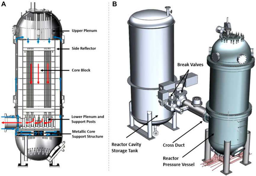
FIGURE 1. (A) Section view of the HTTF RPV showing the helium flow path; (B) HTTF system CAD model.
Graphite prismatic block structure in the MHTGR is simulated by ceramic blocks in the test facility to capture prototypical core temperature profiles. The HTTF reactor core is built of 10 hexagonal core blocks that are made of a cast ceramic, Greencast 94-F (96.5% Alumina). The reactor core is surrounded by several reflectors on each side (two upper reflectors, three bottom reflectors, and side reflectors). The side reflectors are made of a cast ceramic, ShotTech SiC 80 (78% Silicon Carbide, 10.5% Silica, 8.3% Alumina) while the top and bottom reflectors are also made of Greencast 94-F. For the MHTGR the permanent side reflectors are made of a different grade of graphite (Stackpole 2020) than the rest of the reflectors and core (H-451 Graphite). These have very different thermal conductivities and thus needed a different ceramic material to scale appropriately. There are also three separate structures designed to model the core exit chamber: lower plenum roof, lower plenum (the chamber that houses 163 support posts), and lower plenum floor. The HTTF core block cross section is shown in Figure 2A. 516 coolant channels and 210 heaters channels are shown in the core block cross section view, indicated by five different colors. Coolant flow channels are shown as blue, green or yellow (depending on the channel diameter) while the voids where the heater rods are placed are shown in red (Figure 2A). Core bypass flow is restricted by the graphite plate placed on the top of upper reflector and instead is accounted for by 6 inner and 36 outer bypass core channels. Core sections denoted as primary, secondary, and tertiary are the only instrumented regions within a single core block. HTTF inlet plenum shroud (Figure 2B) is assembled with 39 guide tubes that hold thermocouples and gas capacitance sensors in place. A total of 42 thermocouples and 6 gas capacitance sensors are placed in the upper head region (Woods, 2018).
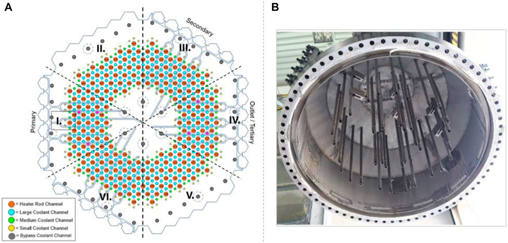
FIGURE 2. (A) Arrangement of coolant channels, bypass channels, and heater rods channels in the HTTF core block; (B) HTTF upper head with instrumented guide tubes.
The facility does not use nuclear fuel to produce power, it is equipped with a network of electrically heated graphite rods (graphite grade G-348) that produce approximately 2.2 MWth. There are 210 heater rods arranged in 10 heater banks, with 3 heater legs per heater bank. Each heater leg consists of 7 heater rods. During a heat-up test in the fall of 2017, several spots within the ceramic core melted. This was because arcing occurred at the interface between graphite rodlets, spiking the local temperatures that exceeded the ceramic melting point. This arcing occurred because the blocks’ thermal expansion at elevated temperatures caused the blocks to shift in position, affecting the contact points between graphite rodlets and misaligning the heating channels. In response to this, several new core blocks were installed, all thermocouples had to be reinstalled, and only four heater banks (103, 104, 107, and 108) were utilized for the tests. There was also a change in the type of heater design to preserve a relatively uniform surface contact area. The consequences of having to implement new core blocks and heaters, as well as reinstall instrumentation, were significant. OSU and INL agreed to only have four heater banks installed, limiting the number of shakedown and possible matrix tests to be performed. Many of the matrix tests planned were supposed to be low power (below 350 kW), but often, the tests typically had power outputs below 150 kW. Additionally, having only four banks resulted in localized (and asymmetric) heating within the core, requiring OSU test engineers to carefully monitor heat up rates during test preparation. In general, limiting the decay power impacted efforts to investigate the effects of core power on system behavior. Non-etheless, tests were completed for various loss of forced cooling (LOFC) events, as well as normal operations.
3 HTTF testing matrix and tests description
In the VHTR PIRT, the Nuclear Regulatory Commission (NRC) identified three main phenomena of interest concerning the safety aspects of the HTGR: primary system cooldown phenomena, core power and temperature distributions, and postulated air-ingress accidents (Ball and Fisher, 2008).
Of particular note, the designer of the HTGR must provide validation of key passive safety phenomena to prove that the design can withstand postulated accidents via passive heat removal. Three types of postulated accidents that the HTTF was designed to examine are PCC and DCC, and DCC with air ingress. The purpose of the testing campaign was to complete integral-level thermal-fluid tests at the HTTF to investigate the phenomenological behavior of conduction cooldown events at a system level.
Table 1 lists tests performed at the HTTF. Tests 1 through 6 focused on characterizing the facility’s operational parameters. Subsequent tests delivered data on the DCC with varying gas temperatures and power levels. PCC, gas mixing, heat up and cooldown tests were also executed. Detailed test acceptance reports providing test data, initial conditions, and limitations are available at https://www.osti.gov/.
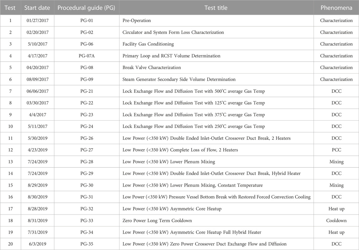
TABLE 1. HTTF- list of performed tests.
3.1 Characterization tests
The objective of the characterization testing was to establish a well-defined operational envelope of the facility and to demonstrate the ability of the HTTF to safely and reliably perform its designed matrix tests. The following list outlines the purpose of each of the executed characterization tests.
• PG-01 Pre-Operation Test (OSU-HTTF-TEST-001)—developed to verify the control of critical components at the Operator Control Center (OCC).
• PG-02 Circulator and System Form Loss Characterization Test (OSU-HTTF-TEST-002)—developed to measure the forced flow differential pressure across components and regions of interest within the primary system over the expected primary gas flow rate range.
• PG-06 Facility Gas Conditioning (OSU-HTTF-TEST-006)—developed to perform all the necessary steps to condition the gas in the test facility for the initial conditions of other design tests.
• PG-07A Primary Loop and RCST Volume Determination (OSU-HTTF-TEST-007)—executed to measure the gas volume needed to bring the system to full pressure.
• PG-08 Break Valve Characterization (OSU-HTTF-TEST-008)—developed to simulate four large break valves blowdown effects.
• PG-09 Steam Generator Secondary Side Volume Determination (OSU-HTTF-TEST-009)—executed to measure the volume of the steam generator vessel.
3.2 DCC tests
The DCC typically involves a break in the pressure boundary of the reactor system resulting in a depressurization. The transient can be divided into three distinct stages: 1) depressurization, 2) gas-ingress (if present), and 3) natural circulation. The gas ingress stage can be further divided into gas-ingress by exchange flow, gas-ingress by molecular diffusion, and gas-ingress by inflow due to coolant contraction during the subsequent cooldown phase. The extent to which the prototypical plant experiences, if at all, gas-ingress by exchange flow or diffusion depends on the location and the size of the break. While the HTTF is capable of performing a variety of transient and normal operation scenarios that happen in the VHTR, it was primarily designed and scaled to mimic the DCC event. Therefore, the majority of experiments performed at the facility aimed at varying core power levels or average temperature differences between the upper plenum floor average and lower plenum inlet jet, which can impact the progression and severity of the DCC stages.
Tests PG-21, 22, 23, and 24 focused on testing the progression of the lock exchange flow between the RPV and RCST, and diffusion air ingress stages with varying average helium temperatures (500, 125, 375, and 250°C). These test results and the impact of varying initial temperature conditions on the air ingress progression were assessed by Glass (2017).
During the execution of the heated DCC tests performed in 2017, the performance of the graphite heaters was closely monitored and observed to degrade with each test until heat could be no longer produced. This was caused by several factors, including core blocks thermal expansion and water accumulation in the RPV ceramic structures. Thermal expansion caused lateral movement of core blocks that impacted graphite rodlets’ alignment and contact. When the contact between rodlets was imperfect or lost, then either arcing or electric circuit failure occurred. Subsequently, large temperatures associated with arcing caused localized graphite sublimation, melting of alumina and blocks cracking. Moreover, the C-Type thermocouples located in the inner core region were degraded due to exposition to temperatures that exceeded the instrument’s maximum temperature (2,315°C). Before the testing campaign was resumed, the graphite rods were redesigned and the facility underwent major maintenance. The original annular graphite rodlets were replaced with bone-shaped ones (with ball and socket endings to facilitate rodlets contact in case of lateral blocks translation caused by thermal expansion). Only four new heater legs (out of 10 that were originally installed) were located in the core. Although the maximum power output was reduced to 880 kW, it allowed for benchmarking the new heating system with a reduced number of legs. In addition, cracked core blocks were replaced, C-Type thermocouples were replaced with R-Type thermocouples. New operation and maintenance procedures to reduce the heat up rate and increase the coolant flow rate during each test were also written. Water accumulation in the ceramic structures is an inherent property of the core and reflectors’ structural material and its removal became a permanent part of the facility conditioning before the matrix testing execution.
In 2019, after the facility was reassembled and conditioned for testing, four additional DCC tests (PG-26, PG-29, PG-31, and PG-35) were executed at varying core power distributions or break locations. To provide an example of the DCC test progression, PG-29 will be described in more detail. This test modeled a break in the HTTF inlet/outlet ducts. It was initiated when the average core temperature was between 550 and 590°C, with the peak temperature being between 780 and 820°C. The pressure was kept at a steady-state (170 kPa), and the outlet temperature on the secondary side was kept consistent at around 118°C. The transient would be initiated by stopping the gas circulator, shutting the steam generator isolation valve, opening the break valves located in the concentric duct, and following the decay heat power curve across four heater banks during the natural convection phase. This was revised during the test, to only incorporate one hybrid heater providing constant power and was initiated with conditions listed in Table 2. The hybrid heater layout is presented in Figure 9A. The test began on 7/24/2019 and was completed on 7/26/2019.
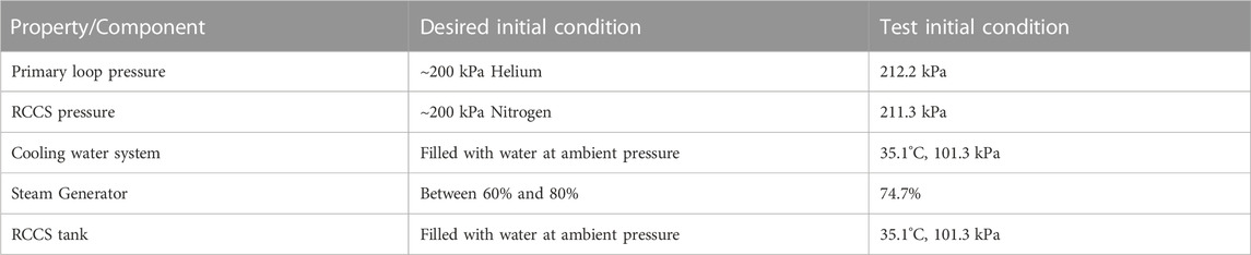
TABLE 2. PG-29 test initial conditions.
The break valves were opened at just over 80 h into the test, about a minute after the circulator was shut off, and the diffusion phase started approximately a minute later. Break valves characteristics are listed in Table 3. The break diameter was scaled as 1:4 (referring to the reference MHTGR design). This ratio is in line with the vessel diameter scaling to reduce test facility to MHTGR similarity group numbers distortions. The break location (shown in Figure 1A) near the RCCS enables counter-current flow development and investigation of the RPV gas ingress via lock-exchange flow.
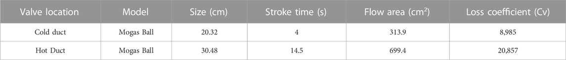
TABLE 3. HTTF cross-ducts break valve characteristics.
The power output during PG-29 was supposed to be kept at a maximum of 48 kW for approximately 80 min to ensure that the ceramic did not exceed the heat-up limit, as well as to preserve the scaled decay heat curve. After this period, the transient natural circulation phase started. Once the DCC was initiated, the steam generator was allowed to cool down. After the initial dumping of steam, the pressure was kept steady at about 120 kPa, and the water inventory was kept at just above 70%. The heaters failed approximately 89 h into the test, prohibiting the operators from following the decay curve. This implies that the core would have lost heat at a faster rate than what was anticipated to happen. The test ended when the motor speed drive for the RCCS pump was set to zero, at approximately 14 h after the start of the natural circulation phase.
After break valves were opened, the hot helium flowed into the RCST as the cold nitrogen flowed toward the PPV. The gases flowed in a counter-current fashion, where the top half of the hot duct contained hot helium flowed in one direction and cold nitrogen propagated towards RPV occupying the bottom half of the duct. The stratified temperature trend indicating the counter-current flow can be observed in Figure 3, where after hour 80 the measurements of TF-3202 and TF-3203 are shown to increase. These two thermocouples are in the middle and upper regions of the hot (outlet) duct, downstream of the vessel (at the entrance to the RCST). In contrast, TF-3201 (placed in the lower section of the hot leg) shows the lowest temperature and relatively steady behavior. It should be noticed that when break valves were opened, the RCST temperatures dropped uniformly to approximately 20°C (that is also observed by looking at the TF-3201 and TF-3202 trends in Figure 3). It is anticipated that this was caused by a pressure difference between the primary loop and RCST. Although the procedure aimed at performing the test at equalized pressure of ∼200 kPa, a pressure difference of several kPa could have existed between the PPV and RCST due to the vulnerability of the system to helium leaks.
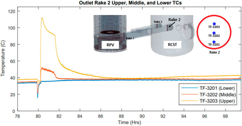
FIGURE 3. Hot leg’s Rake 2 thermocouples readings starting in the 78th hour of the PG-29 test (Woods, 2019).
If natural circulation was to occur, the expectation is that the thermocouples at the top of the core would register a temperature that is higher than at the bottom of the core. Figure 4 shows the inlet (within core block 9) and outlet core coolant temperatures (thermocouples located in the inlet to the lower plenum). Based on these temperatures, it appears that natural circulation might be occurring, since the thermocouples at the inlet become substantially higher than that observed within the lower plenum.
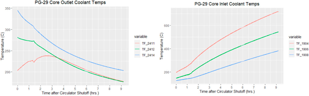
FIGURE 4. PG-29 core outlet (left) and inlet (right) coolant temperatures.
One additional indication that fluid is flowing upwards through the core is to look at the fluid thermocouple readings in the upper plenum (Figure 5). If natural convection is occurring, and hot gas is flowing upward through the core, gas temperatures in the upper plenum should and are increasing throughout the transient. The temperatures in the uppermost part of the upper plenum are observed to increase at a faster rate, which may imply that the radiative and convective heat transfer from the RPV to the RCCS panels is not occurring at a rate sufficient enough to maintain steady-state conditions. The upper plenum gas temperature profile presents a small drop in temperature when valves are opened, leveling out after approximately 2 hours and rising from hour 82 onward. Gas appears to be well mixed as there is little to no temperature difference between the upper and lower regions.
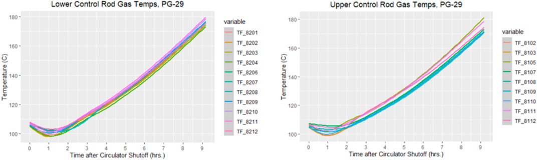
FIGURE 5. PG-29 upper plenum, lower (left) and upper (right) control rod gas temperatures.
3.3 PCC tests
During the PCC event, forced circulation is lost and the pressure boundary remains intact, preventing any significant system depressurization and outside gas ingress into the primary system. Following the loss of pumping power, it is expected that flow reversal will occur as the original coolant inertia is overcome by buoyant and frictional losses. This is similar to all of the DCC events. This phenomenon is expected since coolant travels downwards through the core channels during normal operations, and after some time, frictional and buoyant forces overcome the coolant’s momentum to reverse the flow pattern. The helium coolant expands as it travels upward through the core channels, cools as it interacts with the upper plenum structural materials, then flows downwards through the upcomer. Determining the onset of phenomena and how coolant velocity behavior will help determine its effect on the core temperature profile, as well as the peak core temperature.
Once flow reversal occurs, it is expected that intracore natural circulation would occur since the steam generator’s thermal center is placed below the core thermal center. This would generate a thermosyphoning effect where some coolant channels experience coolant flowing upwards, and somewhere it flows down. Rather than striking the lower plenum, the hot jets should strike the upper plenum structures, and these structures should be cooled predominantly through radiative heat transfer. In the HTTF, however, the SG thermal center is placed above the core thermal center, and there should be natural convection observed throughout the loop.
Natural circulation in many parallel vertical channels with different heat inputs is quite complicated because the flow rate and direction depend on the time history of the heat input of each channel. It is desirable to know at what point the fluid buoyancy becomes significant (onset of mixed convection) and predict the threshold of flow instabilities (Gutowska and Woods Brian, 2019). It is also desirable to determine what the temperature behavior is like in the core channels and upper plenum to witness this thermosyphoning event. This is done via the PG-27 test, which does not exactly replicate the same chronological events that would occur within the VHTR or GA-MHTGR. For one, the circulator in the GA-MHTGR has a coast-down period; the HTTF would immediately cease forced convection, resulting in almost near-instantaneous flow stagnation. To establish the desirable initial conditions for the transient, the cold valve on the secondary side of the steam generator was closed during the test to limit the loop natural convection flow to the intracore natural convection flow. The PG-27 test initial conditions are listed in Table 4. Another hybrid heater configuration (Figure 6A) with two heater banks (102 and 104) was operated during the test with a power output of approximately 66 kW for each bank.
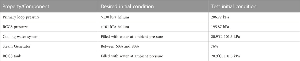
TABLE 4. PG-27 test initial conditions.
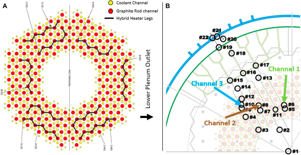
FIGURE 6. (A) PG-27 hybrid heater configuration; (B) Selected instrumented coolant channels for PG-27 experimental data assessment.
During the PCC test, the coolant flowing through the HTTF core successfully stagnated. It is apparent, however, that none of the coolant channels investigated (3 channels located at different core radial locations shown in Figure 6B, analyzed for all three instrumented sectors) explicitly showed a thermosyphoning effect. A sample of this observation is given in Figure 7 : the vast majority of thermocouples had relatively hot temperatures at the channel midlevel (TF-1508, TF-1708), with relatively cooler temperatures at the top of the core (TF-1908). Some channels had the hottest temperatures towards the bottom of the core (indicating downflow), whereas no channels sampled had their hottest temperatures occur at the top of the core. In contrast, velocity data obtained from the pre-test RELAP5-3D simulation of the HTTF PCC test (simulation performed with different heat input) show that middle and outer core rings flow reverses almost immediately after transient initiation, followed closely by that in the inner core ring (Bayless, 2018a; Bayless, 2018b).
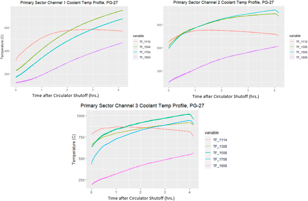
FIGURE 7. PG-27 Core primary sector, selected coolant channels temperature profiles (channels 1, 2, 3 representing inner, middle and outer core radial locations respectively).
The upper plenum temperature profile resembles a similar trend to the PG-29 test: hot helium plumes enter the upper plenum and heat its structures. Based on Figure 8, it is shown that the two thermocouples registering temperatures for the upper plenum shroud indicate a substantial decrease, then increase, in temperatures. This provides some evidence that a thermosyphoning effect is taking place, although these hot jets do not align with or come from the coolant channels that were instrumented with fluid thermocouples. The minimum in both trendlines occurs at around the same time, and may formally indicate when stagnation ends as well as when buoyancy forces dominate. The initial decrease likely indicates a time when there was no coolant flow.
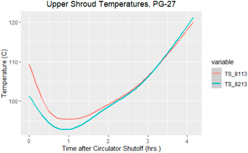
FIGURE 8. Upper plenum shroud temperatures during PG-27.
3.4 Mixing tests
The Phenomena Identification and Ranking Table (PIRT) report identifies a possible fragility of the HTGR due to hot streaking (temperature fluctuations due to imperfect mixing between hot and cold jets exiting from the core and bottom reflectors) (Chen et al., 2014). Temperature fluctuations on the structures downstream (on the lower plenum, then propagating to the hot gas duct walls and even to the steam generator or turbine blades) may induce prolonged exposure to thermal stresses (Landfried et al., 2019).
Two tests were conducted at the HTTF to provide data for the lower plenum mixing simulations validation: PG-28 and PG-30. The purpose of these tests was to investigate the impact of changes in the system mass flow rate and core power on the lower plenum mixing and thermal profiles. The main difference between these two mixing tests was that PG-28 was executed at a constant power level of ∼25 kW while PG-30 power input was gradually increased from 30 to 58 kW. The heaters distribution used during both tests is shown in Figure 9A. The top view of the lower plenum structure presenting lower plenum support posts and instrumented posts placement is given in Figure 9B. The following figure (Figure 10) presents power, lower plenum post #92 temperatures, and circulator speed distributions over both tests duration. In response to each gas flow rate change, there was a sudden temperature change (drop in the PG-28 test and increase in the PG-30 test, as expected). Validation analysis for the PG-28 test using RELAP5-3D and STAR-CCM + codes was performed by Halsted (2022) (Halsted, 2022).
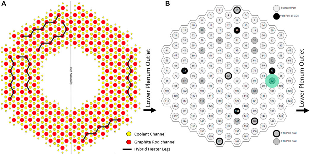
FIGURE 9. (A) Heater legs that were operated during the PG-28, PG-29 and PG-30 tests. (B) Lower plenum top view, with support and instrumented posts location (highlighted in green is the post 92 placement with thermocouples readings used to generate temperature plots in Figure 10).
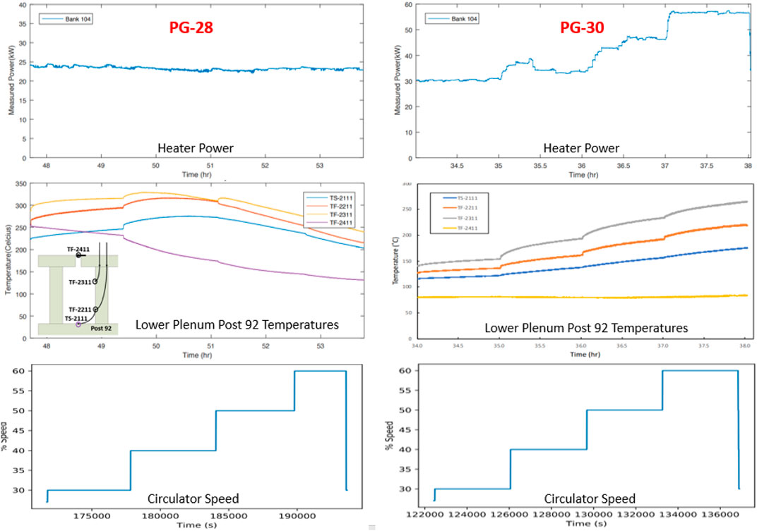
FIGURE 10. Power, lower plenum post #92 temperatures, and circulator speed distributions over the duration of the test PG-28 (left) and PG-30 (right).
3.5 Heat up tests
The heat up tests allow for addressing the phenomena of core flow distribution changes due to temperature gradients identified in the PIRT tables (Normal Operation, 20%–100% power) as a phenomenon characterized by medium knowledge level and of medium importance to plant safety. The purpose of the heat up tests (PG-32 and PG-34) was to examine the facility’s thermal profile and the rate of change in the core temperatures under asymmetric heating conditions. The input power during PG-32 started at approximately 10 kW and was increased steadily during testing to a peak final power of 30 kW with a constant circulator speed (25% of the rated speed). While the power input was kept at a similar level during the PG-34 test, the circulator speed was set to 30% of the rated speed, therefore one can observe a slower heat up rate compared to PG-32 (Figure 11).
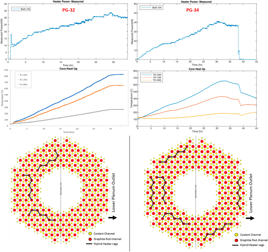
FIGURE 11. Heater Power, core heat up rate (temperature distribution) and operational heaters distribution during tests PG-32 (left) and PG-34 (right).
Both heat up tests were executed without running the RCCS. Therefore useful data can be extracted from analyzing the facility heat up during the PG-28 test conditioning (when the RCCS pump motor speed was set to 30% range) and comparing with PG-32 and PG-34 (outside of the scope of this paper).
3.6 Cooldown tests
The purpose of the PG-33 test was to examine the long-term passive cooldown of the HTTF through conduction and convection within the vessel and radiation and convection outside of the vessel. The test was initiated after completion of the PG-31 and continued for 5 days as the core and system cooled down. Figure 12 shows the core ceramic temperature at 4 different axial locations. Throughout this test, exponential decrease in the core ceramic temperatures is observed.
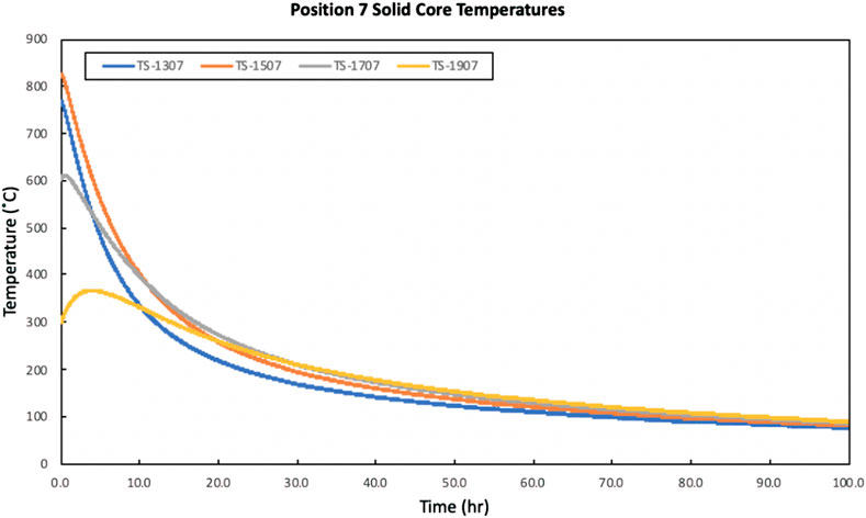
FIGURE 12. Core ceramic temperatures during PG-33 test.
3.7 Experimental data uncertainty and limitations
The selected instruments channels uncertainties (that includes both the systematic and random uncertainties) are shown in Table 5. Data were collected at 1.0 Hz sampling rate.
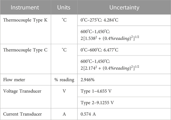
TABLE 5. HTTF Instruments uncertainty.
For the tests examined in this paper, none of the HTTF gas concentration sensors worked. This is problematic since understanding how the gas concentrations change during a DCC event is imperative for understanding how the lock exchange and diffusion mechanisms work during the gas-ingress phase. It is also challenging to find instruments that would operate at HTTF extreme temperature conditions and do not significantly affect the flow field distribution. Moreover, central to correctly quantifying the energy balance and core conditions before any transient within the HTTF is knowing the mass flow rate in the primary loop. The ability to quantify the mass flow rate directly permits the investigator to deduce important parameters such as frictional losses across the core and in plenums, where form factors are difficult to quantify. Although these data were also missing from the HTTF results, the helium mass flow rate during forced flow conditions can be indirectly derived from the circulator pump curve and system energy balance. There were multiple times through the HTTF tests where helium leaked out of the primary loop and additional helium had to be added. Most of these leaks occurred at valve fittings, flanges, and instrumentation bulkheads. Preventing helium leaks is not an easy task because of its small molecule size, but can be reduced if tests are conducted to find where leaks occur, and an adhesive is placed to seal the leak. These preventive actions were taken at the facility to the maximum possible extent. Another alternative is to find a surrogate gas that has a larger molecule size. Implementing this strategy requires a scaling analysis to track the distortions that may occur from using a different gas. The gas leakage along with administrative constraints prevented addressing the HTTF’s ability to generate similar results for multiple tests performed under the same operational conditions (data repeatability).
4 Conclusion
The OSU HTTF is first of a kind IET facility to deliver experimental data on depressurized and pressurized conduction events, heat up, cooldown and mixing phenomena during normal operations in gas-cooled reactors at prototypical temperatures. While the facility assembly and operation came with several challenges, gathered data and accumulated research experience create solid foundations for future gas-cooled reactors testing programs. The facility delivered data on 20 tests, out of which six were developed to characterize the facility operational features, eight modeled the DCC event, 1 was focused on the PCC transient, two aimed at simulating mixing scenario and the remaining experiments tested facility heat up and cooldown conditions. Obtained test data can be used for thermal hydralic codes validation. Data from tests PG-27, PG-28, and PG-29 will be used in the HTTF thermal-hydraulic benchmark exercise for gas cooled reactors applications organized by OECD and led by INL, OSU, CNL, ANL, NRG, and UTK. Test data are available at https://osti.gov.
The HTTF DCC test results provide data on the air ingress and natural circulation stages without depressurization. Data available are the thermocouples and power sensors readings. These results are addressing experimental data needs for some of the major phenomena or system characteristics identified in the VHTR PIRT D-LOFC chart, including:
• Core effective thermal conductivity,
• Cavity Gas stratification and mixing,
• Duct exchange flow.
The facility is further capable of addressing additional D-LOFC phenomena identified in the PIRT tables if the testing campaign is resumed and upgraded instrumentation (for instance gas concentration sensors) is available.
• RCCS spatial heat loadings,
• Coolant flow and thermal properties for mixed gases in the vessel,
• Heat transfer correlations for mixed gases in the core,
• Core and core support structures oxidation,
• Molecular diffusion (maximum core temperature, gas distribution, time scale).
The HTTF PCC test results are also addressing experimental data needs for some of the major phenomena or system characteristics identified in the VHTR PIRT P-LOFC chart, including:
• Inlet plenum stratification and plumes,
• Radiant heat transfer from the top of the core to upper vessel head,
• Core coolant flow distribution (addressed partially—some data can be derived from temperature readings).
Similarly to DCC testing capabilities, the facility is further capable of addressing additional P-LOFC phenomena identified in the PIRT tables, if the testing campaign is resumed, upgraded instrumentation is available and some design changes are introduced (if needed):
• RCCS spatial heat loadings,
• Core coolant (channel) bypass flow (if core blocks structure is redesigned),
• Coolant flow friction/viscosity effects.
The future work includes the execution of an experimental campaign that will address the PCC, DCC, and normal operation PIRT phenomena that have not yet been tested (listed above). The facility can be also accommodated for pebble-bed gas-cooled reactors PIRT testing and gas-cooled reactors components and subsystems testing at elevated temperatures and in a helium environment.
Data availability statement
The datasets presented in this article are readily available. Requests to access the datasets should be directed to US DOE.
Author contributions
IG and BW contributed to the design and implementation of the research, to the analysis of the results, to the writing of the manuscript, and were involved in executing the HTTF tests. JH contributed to assessing PG-27 and PG-29 results, and to the writing of the manuscript.
Conflict of interest
The authors declare that the research was conducted in the absence of any commercial or financial relationships that could be construed as a potential conflict of interest.
Publisher’s note
All claims expressed in this article are solely those of the authors and do not necessarily represent those of their affiliated organizations, or those of the publisher, the editors and the reviewers. Any product that may be evaluated in this article, or claim that may be made by its manufacturer, is not guaranteed or endorsed by the publisher.
References
ASME V&V 20-2009 (2016). Standard for verification and validation in computational fluid dynamics and heat transfer”. New York, NY, USA: American Society of Mechanical Engineers.
Ball, S., and Fisher, S. (2008). Next generation nuclear plant phenomena identification and ranking tables (PIRTs) (Rockville, MD, USA: Nuclear Regulatory Commission). NUREG/CR-6944.
Bayless, P. D. (2018). RELAP-3D pre-test prediction for high temperature test facility test PG-26. IIdaho Falls, ID, USA: Idaho National Laboratory. INL/EXT-18-45717.
Bayless, P. D. (2018)RELAP5-3D input model for the high temperature test facility IIdaho Falls, ID, USA: daho National Laboratory. INL/EXT-18- 45579.
Chen, F., Dong, Y., Zheng, Y., Shi, L., Li, F., and Zhang, Z. (2014). Progress of the HTR-10 measured data utilization. International conference on nuclear engineering. Proc. ICONE 3. doi:10.1115/ICONE22-30088
Glass, M. (2017). Effect of initial conditions and depressurization on lock exchange flow after a depressurized conduction cool-down event in the high temperature test facility. Corvallis, Oregon: Oregon State University.
Gutowska, I., and Woods Brian, G. (2019). “CFD assessment of LOFA intra core natural circulation in the high temperature test facility,” in Proceedings of the NURETH-18, Portland, Oregon, Auguest 2018.
Halsted, J. K. (2022). Validation analysis for the OSU HTTF PG-28 test using relap5-3D and star-ccm+. Corvallis, Oregon: Oregon State University.
Hishida, M., Fumizawa, M., Takeda, T., Ogawa, M., and Tekenaka, S. (1993). Researches on air ingress accidents of the HTTR. Nucl. Eng. Des. 144, 317–325. doi:10.1016/0029-5493(93)90147-2
Landfried, D. T., Kristo, P., Clifford, C. E., and Kimber, M. (2019). Design of an experimental facility with a unit cell test section for studies of the lower plenum in prismatic high temperature gas reactors. Ann. Nucl. Energy 133, 236–247. doi:10.1016/j.anucene.2019.05.037
Maruyama, S., Fujimoto, N., Sudo, Y., Murakami, T., and Fujii, S. (1994). Evaluation of core thermal and hydraulic characteristics of HTTR. Nucl. Eng. Des. 152 (1-3), 183–196. Issues. doi:10.1016/0029-5493(94)90084-1
Qin, S., Song, M., Vietz, S. H., T Pham, C. B., Plummer, M., and Strydom, G. (2022). High-temperature gas-cooled reactor research Survey and Overview: Preliminary data Platform construction for the nuclear energy university Program. United StatesAvailable At https://www.osti.gov/servlets/purl/1887092. doi:10.2172/1887092
Rousseau, P. G., and van Staden, M. (2008). Introduction to the PBMR heat transfer test facility. Nucl. Eng. Des. 238 (11), 3060–3072. HTR-2006: 3rd International Topical Meeting on High Temperature Reactor TechnologyISSN: 0029-5493.
Schultz, R. R., Ougouag, A. M., Nigg, D. W., Gougar, H. D., Johnson, R. W., Terry, W. K., et al. (2008). Next generation nuclear plant methods research and development technical Program plan. United StatesAvailable At https://www.osti.gov/servlets/purl/950995.doi:10.2172/950995
Woods, B. G. (2019). Integral system testing for prismatic block core design HTGR. Washington, DC, USA: OSTI. United States. Web. doi:10.2172/1580081
Woods, B. G. (2018). OSU high temperature test facility design technical report. OSU-HTTF-TECH-003-R2available at: https://www.osti.gov/biblio/1599410-osu-high-temperature-test-facility-design-technical-report-revision.
Nomenclature
Abbreviations
ANL Argonne national laboratory
CNL Canadian national laboratories
DCC Depressurized conduction cooldown
DOE Department of energy
NEUP Nuclear energy university program
D-LOFC Depressurized loss of forced cooling
GA General atomics
GT-HTR Gas turbine high temperature reactor
HPTU High pressure test unit
HTGR High temperature gas cooled reactor
HTTF High temperature test facility
HTTR High temperature test reactor
HTTU High temperature test unit
HTR-PM High temperature pebble bed modular nuclear reactor
INL Idaho national laboratory
JAERI Japan atomic energy agency
MHTGR Modular high temperature gas cooled reactor
NGNP Next-generation nuclear power
NRG Nuclear research and consultancy group
PIRT Phenomena identification and ranking tables
PCC Pressurized conduction cooldown
PG Procedural guide
P-LOFC Pressurized loss of forced cooling
PPV Primary pressure vessel
RCCS Reactor cavity cooling system
RCST Reactor cavity storage tank
RELAP Reactor excursion and leak analysis program
RPV Reactor pressure vessel
OECD Organization for economic cooperation and development
OSU Oregon State University
TF Fluid thermocouple
TS Solid thermocouple
UTK University of Tennessee Knoxville
VHTR Very high temperature gas cooled reactor
Keywords: HTGR, PCC, DCC, SET, gas-cooled reactor, thermal-hydraulic codes
Citation: Gutowska I, Woods BG and Halsted J (2023) Developing PCC and DCC integral effects test experiments at the High Temperature Test Facility. Front. Energy Res. 11:1088070. doi: 10.3389/fenrg.2023.1088070
Received: 03 November 2022; Accepted: 11 January 2023;
Published: 24 January 2023.
Edited by:
Mark David DeHart, Idaho National Laboratory (DOE), United StatesReviewed by:
Palash Kumar Bhowmik, Idaho National Laboratory (DOE), United StatesCarlos Estrada, Idaho National Laboratory (DOE), United States
Copyright © 2023 Gutowska, Woods and Halsted. This is an open-access article distributed under the terms of the Creative Commons Attribution License (CC BY). The use, distribution or reproduction in other forums is permitted, provided the original author(s) and the copyright owner(s) are credited and that the original publication in this journal is cited, in accordance with accepted academic practice. No use, distribution or reproduction is permitted which does not comply with these terms.
*Correspondence: Izabela Gutowska, Z3V0b3dza2lAb3JlZ29uc3RhdGUuZWR1