 Shuang Wen1,2
 Rui Zhang
 Xinlu Tian
- 1Nuclear and Radiation Safety Center, Ministry of Environmental Protection, Beijing, China
- 2State Environmental Protection Key Laboratory of Nuclear and Radiation Safety Regulatory Simulation and Validation, Beijing, China
- 3College of Nuclear Science and Technology, Harbin Engineering University, Harbin, China
After the reactor core melt, the thermal impact of high temperature molten mixture to the lower head of reactor pressure vessel (RPV) will cause the shape change of cooling channel constituted by reactor pressure vessel outer surface and other supporting structures. This phenomenon may lead to local heat transfer deterioration and then cause the failure of in-vessel retention (IVR). Therefore, it is necessary to study the reactor pressure vessel deformation under in-vessel retention conditions. This paper proposes a numerical method for the CHF of the outer wall of reactor pressure vessel using ANSYS and FLUENT. The geometry of coolant channel is modeled by ANSYS with the coupling of temperature and mechanical field analysis in ANSYS, and the critical heat flux (CHF) of reactor pressure vessel outer surface is further predicted by FLUENT. With the comparing between test data and calculation, the calculation methods are verified. The results show that the CHF will be decreased by the deformation of PRV caused by the core melt.
1 Introduction
As an important solution for mitigating the consequences of severe accidents, in-vessel retention (IVR) through pressure vessel external cooling (ERVC) has been more and more widely used. IVR-ERVC relies on natural circulation to cool the outer wall of the reactor pressure vessel (RPV), taking away the decay heat generated in the reactor, so that the outer wall of the RPV is always at a lower temperature, thus maintaining the structural integrity of the RPV. When the core melting accident occurs, the cooling water enters the cooling channel formed by the outer wall of the RPV and the outer insulation layer from the lower chamber to cool the RPV.
The concept of IVR-ERVC was first proposed by Condon in 1982. Since then, the researchers conducted numerous experiments to verify the IVR capability in the event of a core meltdown. However, the use of three-dimensional numerical simulation method to evaluate the reliability of critical heat flux (CHF) with a deformation of pressure vessels after severe accidents is relatively rare.
The CYBL experiment carried out by Chu et al. (1997) used a pressure vessel with a ratio of 1:1 to conduct an experimental study on the boiling heat transfer and flow process in the external cooling process. Different from the AP600/1,000 reactor pressure vessel, the lower head of the RPV in the CYBL experiment is an ellipsoid structure. Affected by the combined effect of the flow channel structure and gravity, the boiling and flow phenomena on the outer surface of the lower head observed by the CYBL experiment had obvious local distribution characteristics. Chu et al. (1997) believes that parameters such as the two-phase boundary layer, degree of subcooling and the local flow distribution are the key issues affecting the external cooling.
Rempe et al. (2003), Kang et al. (2006), and Park et al. (2006) carried out SBLB experiments, HERMES-HALF and HERMES-1D experiments respectively. In the SBLB experiment, a scaled experimental device model was used to simulate the external cooling system of the pressure vessel, and the effects of the APR1400 thermal insulation layer structure and the heat transfer enhanced coating on the outer surface of the lower head on CHF were studied. After optimizing the structure of the thermal insulation layer and adding the surface coating, the overall heat transfer capacity of the external cooling of the pressure vessel was significantly enhanced, and the highest critical heat flux density reached 2.5 MW/m2. Combined with the CHF data of the SBLB experiment and the analysis of the heat transfer phenomenon, F. B. Cheung proposed a theoretical model that can calculate the CHF distribution on the outer wall of the lower head from the theoretical point of view of liquid film evaporation in the boundary layer (Kang et al., 2006); in this model, the local cavitation fraction and the flow pattern distribution of two-phase flow has an important influence on CHF.
The HERMES series of experiments carried out by Park et al. (2006) adopts the cold experimental method to simulate the two-phase natural circulation flow process of the pressure vessel by injecting air into the experimental section. The experimental results are only limited to the flow phenomenon and the influence of the inlet and outlet area, and the local distribution characteristics of the two-phase flow in the external cooling channel have not been studied.
In 1994, Rouge (1997) of the French Grenoble Nuclear Safety Research Center carried out experimental research on external cooling on the SULTAN experimental device. According to the CHF value measured experimentally, Rouge believes that the cooling capacity of the external cooling of the pressure vessel can reach more than 1 MW/m2.
The ULPU experiment carried out by Theofanous et al. (1997) at the University of California, Santa Barbara, aims to measure the critical heat flux density on the lower head surface, optimize the structure of the thermal insulation layer, and reveal related heat transfer flow phenomena. The ULPU experimental data provided support for the engineering validation of the IVR-ERVC technology for the AP600 and AP1000, and enabled the external cooling measures of the AP series reactors to pass the US-NRC safety review. However, the ULPU experiment has not done in-depth and detailed research on the flow and heat transfer phenomena in the external cooling process of the pressure vessel, and its experimental parameters have very limited effects on the basic phenomenon of external cooling and in revealing the boiling mechanism of IVR-ERVC. For this experiment, EDF (Jamet et al., 2015) used the self-developed computational fluid dynamics (CFD) program NEPTUNE-CFD to carry out numerical simulation of the experiment.
Based on the heat transfer relationship of the molten pool, which obtained from the heat transfer characteristics experiment of the molten pool and the CHF relationship, which obtained from the external cooling experiment of the pressure vessel, many scholars have established the IVR analysis and calculation model of the lower head of the pressure vessel under severe accidents. Professor Theofanous (Theofanous et al., 2004) from the University of California, Santa Barba (UCSB) and Professor Rempe (Rempe et al., 1997) from the Edwards Engineering and Environmental Laboratory (INEEL) established mathematical models for IVR analysis of AP600 pressure vessels respectively. The different melt configurations that may exist in the lower head of the pressure vessel are analyzed, and the thermal response of the lower head wall under the corresponding conditions is calculated.
Khatib-Rahbar et al. (1996) established one-dimensional and two-dimensional IVR analysis models of the lower head respectively, and found that the one-dimensional heat transfer model of the lower head can also accurately predict the wall of the lower head by comparing the results of the thermal response calculation of the lower head wall. About the thermal response Khatib-Rahbar et al. (1996), Esmaili and Khatib-Rahbar, 2004, and Esmaili and Khatib-Rahbar, 2005 established a one-dimensional mathematical model for the structure of the lower head of the AP1000 nuclear power plant pressure vessel, and carried out the analysis of the two-layer and three-layer molten pool configurations that may be formed in the lower head of the AP1000 pressure vessel. The thermal response and IVR margin of the pressure vessel wall are studied by analysis and calculation. Rempe and Knudson, 2004 and Rempe et al., 2005 used SCDAP/RELAP5-3D to carry out IVR analysis and calculation for APR1400, and the results believed that when IVR was implemented, ordinary pressure vessels would be melted through, while pressure vessels treated with porous media coating would not will be melted through, and the results calculated by the VESTA program consider that the heat flux density on the wall of the lower head is lower than the CHF value.
Shanghai Jiao Tong University (Yong-chun and Yan-hua, 2010) built a 1:1 ratio pressure vessel lower head external cooling loop experimental device based on the CPR1000 nuclear power plant pressure vessel lower head structure. The test section is a two-dimensional pressure vessel lower head slice. The experimental device was used to study the natural circulation cooling characteristics of the outer wall of the lower head of the CPR1000 pressure vessel. Through non-heating experimental research, they believe that the inlet and outlet area of the lower head test section of the pressure vessel is the main factor affecting the natural circulation capacity. Optimizing and improving the inlet and outlet flow channel structure of the test section can reduce the flow resistance and improve the natural circulation cooling capacity.
Shanghai Jiao Tong University and Chengdu Nuclear Power Research and Design Institute (Wen et al., 2012) jointly studied the dynamic characteristics of the bubbles on the surface of the inclined rectangular channel heated downward. They used a visual experimental device to simulate the pressure vessel under the pressure vessel by changing the inclination of the rectangular channel. The wall surface at different positions of the head, the position of the rectangular channel can be changed from 0° to 30°, and the size of the rectangular channel can be changed from 3 mm to 8 mm. Their experimental results indicate that the detachment of the fluctuating interface of steam and water on the heating surface is the main cause of CHF generation.
In terms of theoretical research, Xi’an Jiaotong University (Yang et al., 2011) established the vapor-liquid two-phase flow boundary layer theory and the micro-liquid layer theory on the wall of the lower head of the pressure vessel, and established the vapor-phase and liquid-phase conservation relations and the boundary layer thickness model in the micro-liquid layer. A theoretical prediction model for the occurrence of CHF on the wall of the lower head of the pressure vessel under the condition of saturated boiling is proposed. Using this model, the change of the wall CHF along the pressure vessel wall was studied, and the influence of different pressure vessel radii on the CHF of the lower head wall was predicted. The calculation results showed that the CHF of the lower head wall decreased with the increase of the radius. But the change is getting smaller and smaller, when the radius increases to a certain value, its influence on CHF can be ignored. The calculated results of the theoretical model are in good agreement with Cheung’s experimental results, thus verifying the correctness of the theoretical prediction model.
In a serious accident, although the IVR-ERVC can cool the outer wall of the RPV, the high-temperature melt in the molten pool will still heat the inner wall of the lower head to a very high temperature, causing thermal expansion and high-temperature creep deformation. Not only that, the core melt will also make part of the RPV wall temperature exceed the melting point temperature of the material, resulting in wall meltdown, which will greatly reduce the wall thickness of the RPV and further aggravate the deformation of the RPV wall. At present, there are few studies on the effect of this phenomenon on the CHF inside the lower head. In order to analyze this problem, this study established a set of analysis methods based on ANSYS and FLUENT software for the heat transfer characteristics of two-phase flow boiling in the outer flow channel of the lower head under the condition of flow channel deformation.
2 Calculation method
In order to analyze the flow and heat transfer characteristics of the coolant in the channel formed between the lower head after high temperature creep deformation and the external insulation layer under the action of high temperature, it is necessary to carry out two parts of work. One is calculating the deformation of the lower head under the action of the internal high temperature melt, and the other is analyzing the CHF characteristics of the coolant flowing in the flow channel formed by the lower head and the outer wall.
The deformation of the lower head under the action of the internal high temperature melt is calculated by ANSYS mechanical analysis software, the CHF characteristics of the coolant at the lower head are calculated by the FLUENT software using the coolant channel geometry computed by ANSYS as input. The calculation process is shown in Figure 1.
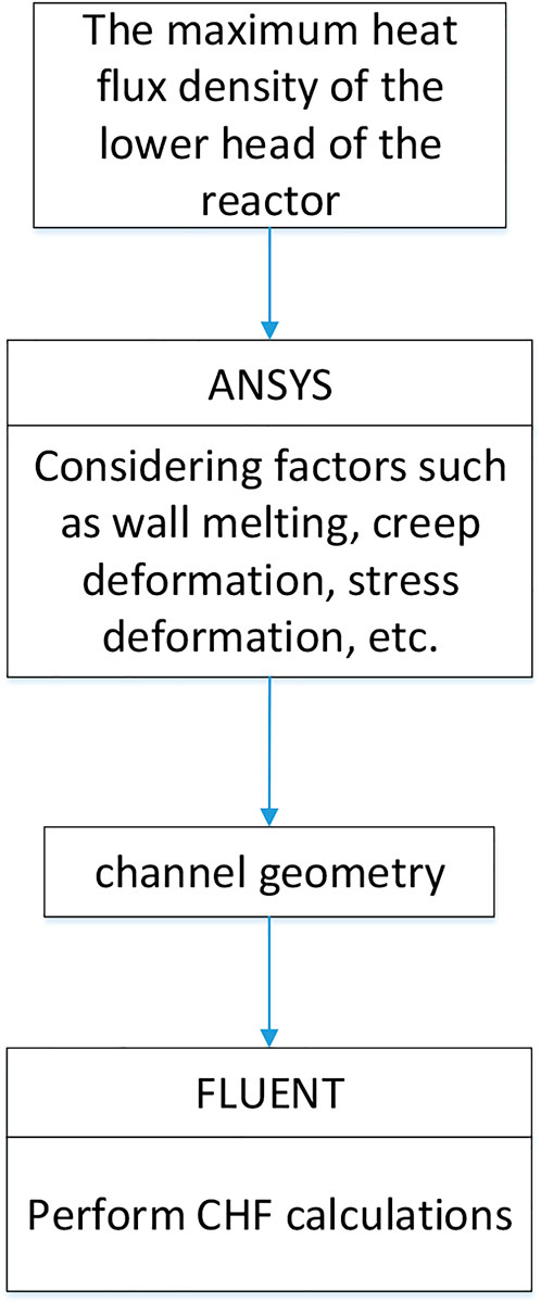
FIGURE 1. Calculation flow chart.
2.1 Methods of mechanical analysis
In this paper, the modeling, meshing, temperature field and mechanical field analysis of the RPV are performed by using the finite element analysis software ANSYS. In order to reduce the calculation time, the RPV is simplified to a two-dimensional axisymmetric model according to the structural characteristics and load characteristics of the RPV. For the purpose of ensuring the calculation quality, the calculation model mainly uses quadrilateral structured meshes, and also a small amount of triangular meshes. The mesh size is about 4 mm. Although the main research object is the RPV lower head in contact with the molten pool, the load acting on the lower cylinder will also affect the calculation results, so the lower cylinder part is also modeled.
The numerical analysis is performed using the indirect method, which is divided into two steps.
The first step is the temperature field analysis, which uses PLANE67 element that can perform thermal analysis to calculate the temperature distribution of the RPV under the most unfavorable operating conditions. The PLANE67 element has four nodes and can be used for 2D (planar or axisymmetric) steady-state or transient thermal analysis. The most unfavorable condition is a condition that has the greatest influence on the deformation of the cooling channel and it can be obtained by analyzing and combining various operating conditions. According to the calculation results of the temperature field, it is judged whether the wall melting phenomenon occurs, and the RPV is re-modeled according to the remaining wall thickness after melting.
The second step is the mechanical analysis of the RPV wall. This step needs to take into account the effects of phenomena such as thermal expansion and creep at high temperatures, so it is necessary to convert the element type to the PLANE42 element that can perform creep analysis. Based on the displacement results of each point on the RPV outer wall surface, the deformation of the cooling channel can be deduced as an input to the CHF study of the RPV outer wall surface, which will provide a more accurate assessment of the RPV outer wall surface cooling capacity.
2.2 FLUENT-based CHF calculation method
2.2.1 Method of CHF calculation
Xi’an Jiaotong University has developed a FLUENT-based method for calculating CHF. The details of the mathematical model (such as the boiling model) and the corresponding CHF simulation method have been given in the references (Zhang et al., 2019). By secondary development on the basis of FLUENT15.0 software, the C language-based User-Defined Function (UDF) can be used to calculate the flow heat transfer characteristics and void fraction distribution in the external flow channel of the pressure vessel under atmospheric pressure. The details on the model can be found in reference (Yang et al., 2011).
2.2.2 CHF criterion
The research objective of this work is to obtain the critical heat flux of the flow channel on the outer wall of the lower head. The CHF monitor methodology used in this paper is controlled by the transition function which is introduced to describe the heat transfer from heated wall to vapor phase. The transition function is shown as follows:
ag,1 and ag,2 are the starting point and the end point of the transition section respectively. The value of the function ranges from 0 to 1 when void fraction in near wall cell changes from 0 to 1. The code determines the heat flux partition by the transition function, and obtains the wall temperature distribution under different heat flux, so the wall temperature rise is essentially driven by the near wall void fraction and the critical void fraction. It is highly acceptable to choose near wall void fraction as the criterion of critical heat flux. According to the experience of Weisman and Pei (1983) and Lavieville et al. (2005), the value of 0.8 is selected in this study. This means that when the local void fraction near the wall surface is higher than 0.8, the direct heat transfer from the wall surface to the vapor phase is initialized, which leads to a change in the heat transfer mechanism near the heated wall surface and triggers the CHF.
2.2.3 Geometry and meshing
The geometry used for the thermodynamic calculations is obtained from the mechanical calculations section. The melting of the inner wall surface of the pressure vessel and the deformation due to creep are considered, and the specific dimensions of the inner wall surface are obtained by thermodynamic coupling calculations.
The grid of channel is shown in Figure 2. The size of near wall grid has certain effect on the calculation of void fraction distribution. A finer near wall grid will achieve a higher void fraction under the same working condition, which is a general conclusion for CHF simulation with Eulerian two-fluid model. So the near wall grid size is an important part worth pay more attention. We have carefully investigated the mesh size to make sure the selected mesh size is applicable for the research object, which has been discussed in our previous published paper (Zhang et al., 2019). As this paper mainly focuses on the effect of pressure vessel lower head creep deformation on the CHF, we did not use much words talk about that.
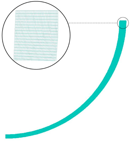
FIGURE 2. Grid of channel.
2.3 Validation of the calculation method
NPCCRI (Teng et al., 2018) carried out tests on critical heat flux at different positions of the outer flow channel of the lower head in the angle range of 30–90°, and the results are used to validate the numerical used in FLUENT in this paper.
The test section is the coolant flow channel formed by the outer wall surface of the lower head and the external insulation layer. The experimental working substance is deionized water, and the inlet of the test section is subcooled water with a subcooling degree of 15 K at the corresponding pressure. The inlet velocity of the cooling water is 0.488 m/s. The profile of heat flux at the heated surface can be altered to allow local boiling crisis at different locations. The heat flux increases step by step until the wall temperature measured by the thermocouple surges. Table 1 shows the experimental conditions and the measured CHF values at different angles.
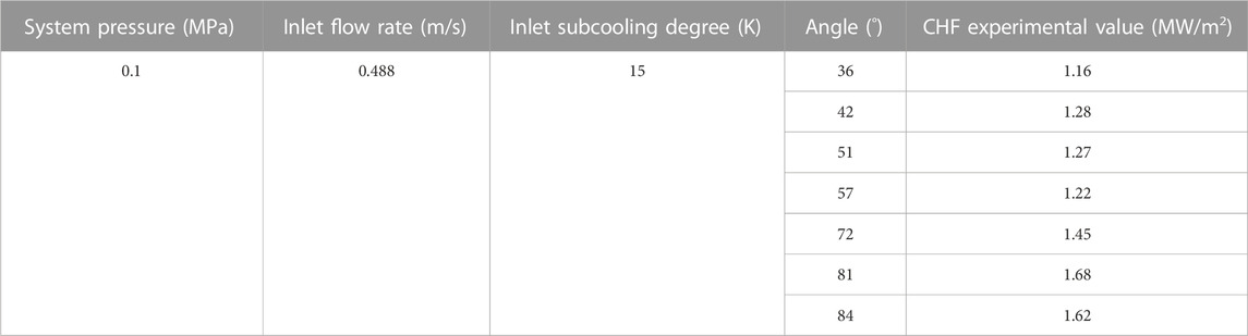
TABLE 1. Experimental conditions.
Due to the low heat flow of the molten pool in the low-angle area at the bottom of the lower head, the possibility of critical heat flux in this area is extremely low. So the experimental design focuses more on the critical value in the high-angle and high-heat flux area, and the test measurement angle range is 30°–90°.
In the calculation and simulation, the heat flux is gradually increased only within one degree of angle, and the corresponding heat flux is analyzed when it reaches the critical value. Taking the calculation of the critical heat flux at the 75° angle position as an example, the heat flux at other positions is determined by the heat flux curve, and the heating heat flow is only gradually increased at the wall position corresponding to the angle between 74° and 75°, with 0.1 MW/m2 as the starting heat flux, and the heat flux is increased in steps of 0.1 MW/m2 until the criticality occurs at this position. It was found that no CHF occurred at 1.4 MW/m2, and finally when the heat flux increased to 1.5 MW/m2 the void fraction near the wall reached more than 0.8. Therefore it was concluded that the CHF for this condition was 1.4 MW/m2. The change curve of the maximum void fraction on the heated wall surface monitored with the iteration step is shown in Figure 3.
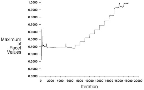
FIGURE 3. Maximum void fraction on the heated wall surface monitored.
The distributions of heat transfer coefficient, wall temperature, and void fraction along the outer wall surface of the lower head under 74°–75° heating condition are given in Figures 4–6, respectively. Overall, the convective heat transfer coefficient on the outer wall surface has a tendency to increase gradually along the lower head. With the increase of angle, voids start to be generated and heat transfer starts to be enhanced. However, at the observation point, the local heat flux is too high, resulting in the formation of an air film on the wall surface, which causes a rapid decrease in the heat transfer coefficient. Afterwards, due to the decrease of heat flux, the bubble generation rate decreases, the air film disappears, and the churning caused by the bubbles breaking away from the wall surface again causes the enhancement of heat transfer. The comparison of different angles of the heating point shows that the gas film is formed only at the local heating point, and then the gas film disappears due to the decrease of the heat flux.
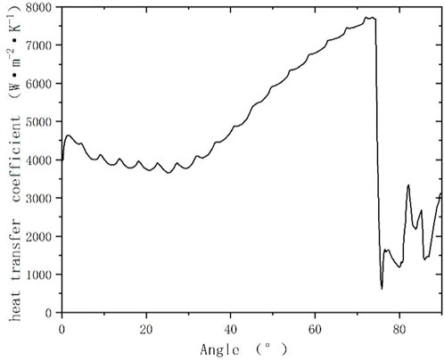
FIGURE 4. Heat transfer coefficient distribution curve along the heating wall.
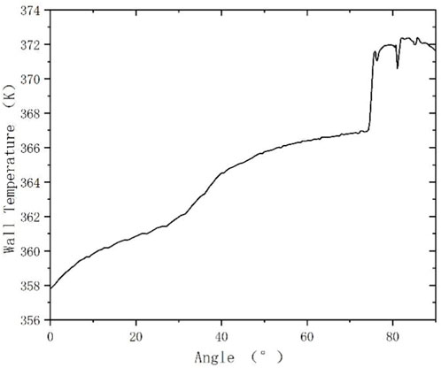
FIGURE 5. Wall temperature variation curve with angle.
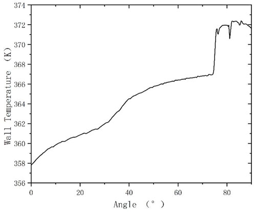
FIGURE 6. Variation curve of the void fraction on the heating wall with angle.
The void fraction in the calculation domain is basically 0, and the bubbles only exist in the near-wall grids, which is due to the fact that only drag force can be considered as the interaction force between the gas-liquid two phases in the Mixture model, and the forces that accelerates the bubbles motion away from the wall into the subcooled mainstream cannot be considered. Thus the vapor phase generated during the calculation is concentrated near the heated wall. The CHF will be triggered when the local void fraction reaches 0.8.
It can be seen from the Figure 6 that the void fraction on the heated wall increases with the increase of the angle. In the low-angle area, the void fraction is close to 0 due to the low wall heat flux, and all of the wall heat flux is used to heat the cooling water. As the temperature of cooling water keeps increasing, the evaporative heat flux used for bubble generation appears, and the wall void fraction gradually increases until it reaches the critical value of 0.8° at the location where CHF occurs, which is mainly due to the continuous increase of and the decrease of coolant subcooling.
The CHF values at different angles of the experimental bench are predicted by the above method, and the predicted results and experimental results are compared in the following Table 2.
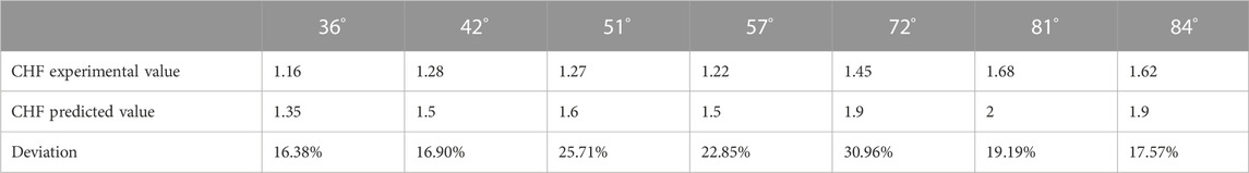
TABLE 2. Comparison of predicted and experimental values of CHF.
A comparison of the calculated and experimental values of CHF at different angles of the external channel of the lower head is given in Figure 7. It can be seen from the graph that the calculated CHF values at different angles are all slightly higher than the experimental measured values, which indicates that the mitigation measure of retaining the core melt inside the pressure vessel by external cooling of the pressure vessel is feasible. Comparing the fitted curves of the experimental data and the calculated results, it can be seen that although there are slight differences in the values, the trends of the fitted curves are almost identical. The CHF measurements gradually increase with increasing angles, and the calculated results give the same predicted trends. The deviation is basically within +30% of the experimental value, which indicates that the CHF trend analysis by this method has certain reliability.
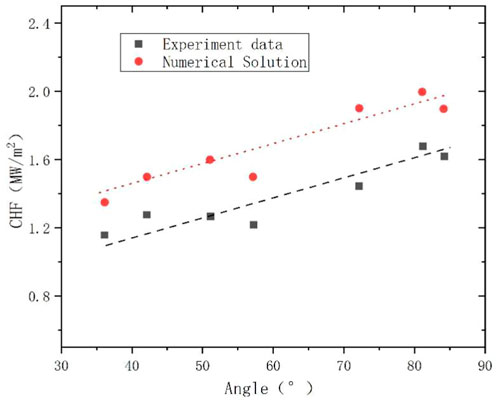
FIGURE 7. Trend of CHF values with angle.
3 Influence of the lower head deformation on the CHF
3.1 Description of working conditions
In this section, the external flow channel of the lower head of the CAP1400 pressure vessel is selected as the research object.
In order to investigate whether the deformation of the lower head in the severe accident case will have any effect on the CHF, the CHF results on the external wall surface of the lower head under two conditions are calculated in this paper. The geometry of Case1 is the original geometry. The geometry of case 2 considers the deformation of the PRV.
3.2 Channel shape
3.2.1 Boundary condition
After the full-scale RPV wall model is established, the temperature field of the RPV wall can be obtained by applying the thermal boundary conditions and thermal loads to the model. During the cooling process, the temperature of the RPV wall will keep changing over time. In order to ensure the conservativeness of the calculation results, the heat flux density transferred from the molten corium in the reactor to the RPV is calculated from the unfavorable condition which selected in many serious accidents that can lead to the melting of the reactor core.
In order to obtain the deformation of the lower head in case 2 by the influence of the internal molten corium, the mechanical analysis of the RPV wall was carried out by using ANSYS software base on temperature field.
The boundary conditions and loads imposed in the calculations include:
1) 400 K is the conservative temperature constraint determined after considering the boiling point, superheat and conservativeness.
2) Input heat flux envelope curve (see Figure 8) at the inner wall of RPV. In this paper, the heat flux curve at the most unfavorable moment from the severe accident conditions is used.
3) Apply pressure of cooling water on the outer wall surface of RPV.
4) Apply pressure of molten mixture on the inner wall surface of the RPV.
5) Apply 1 MPa pressure to the inner wall surface of the RPV. Once the internal pressure exceeds 1 MPa, the IVR strategy is considered to be invalid.
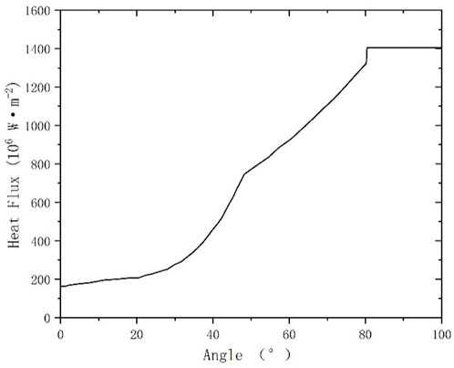
FIGURE 8. RPV inner surface heat flux.
3.2.2 Calculation result
The resultant temperature distributions are shown in Figure 9. The calculated temperatures exceed the material’s melting point of 1600 K at many locations, these areas are melted and cause the RPV walls to become thinner. The thinning of solid part of the RPV wall has significant effects on its deformation. The treatment adopted in this paper is to re-model the RPV based on the results of the temperature field. Figure 10 gives a comparison of the finite element model of the RPV before and after the core melt. It can be seen that over 80% of the wall thickness is melted at certain angles.
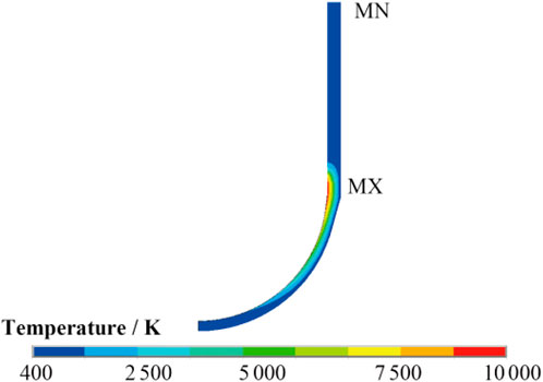
FIGURE 9. Temperature fields of RPV.
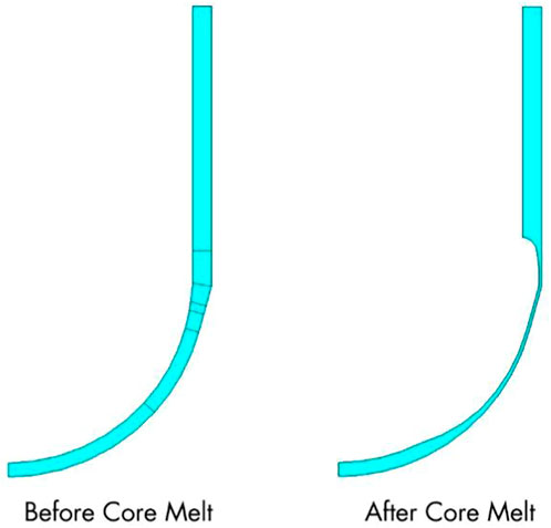
FIGURE 10. RPV before and after the core melt.
Using the new RPV model, the results of the mechanical field can be obtained by applying the same boundary conditions and loads used for the temperature analysis mechanical boundary conditions. The deformation caused by creep changes continuously with time. The calculation is based on a conservative principle that the cooling time is 100 h and the heat flux applied on the inner wall surface of the RPV does not decrease during the whole process. Since the purpose of the calculations is to analyze the cooling channel deformation caused by the expansion of the RPV wall, the calculations focus on the displacement of the outer wall of the RPV, which has a direct effect on the shape of the cooling channel.
The RPV deformation results obtained by mechanical analysis shows that when only thermal expansion is considered, the overall RPV expands 13.11 mm along the vertical direction; on this basis, after the effect of internal pressure and other loads are taken into account, the RPV expands 0.61 mm more to 13.72 mm along the vertical direction; and after 100 h creep, the RPV continues to expand to 13.85 mm along the vertical direction and then remains stable. It can be seen that under IVR conditions, the main factor causing RPV deformation and cooling channel narrowing is thermal expansion. Although high temperature creep fracture is the main mode of RPV failure, the effect of creep deformation on the overall RPV deformation is much less than thermal expansion.
The deformation of the cooling channel between the RPV outer wall and the insulation layer can be determined from the calculated expansion values of the RPV outer wall along various angle. The results show that the width of the cooling channel is reduced compared to the initial design value, due to the deformation of the RPV lower head under IVR conditions, and the reduction value varies between 13.85 and 18.75 mm at different angles, as shown in Table 3. 0° is the bottom of the RPV lower head, and 90° is the top of the lower head. The width of the external cooling channel is 90–150 mm, which means that the maximum deformation of the RPV outer wall under IVR conditions reduces the width dimension of the outer cooling channel by about 1/10–1/5. The deformation of the cooling channel is determined by the displacement of the RPV outer wall rather than the strain. Therefore, although the maximum RPV local strain appears near 0°, but the maximum deformation occurs at an angle of about 45° where accumulates the maximum vertical and horizontal displacement.
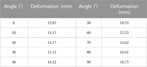
TABLE 3. Maximum dilatation of RPV.
3.3 Analysis of the effect of deformation on the characteristics of CHF
3.3.1 Geometric
According to the calculated the thermal stress creep deformation and creep deformation on the outer wall of the pressure vessel lower head, the dimensions of the geometric model of the external flow channel is determined. By comparing the original size of the lower head flow channel and CHF characteristics of the coolant flow channel after deformation, the CHF characteristics in the outer coolant flow channel of the pressure vessel lower head formed before and after the deformation of the pressure vessel are analyzed, and then the influence of the deformation of the lower head on the CHF is obtained.
Geometric model 1 is not considering deformation, while Geometric model 2 is the geometric flow channel obtained by considering the deformation of the outer wall of the pressure vessel, based on mechanical calculations.
3.3.2 Grid
Since the geometric model of the external flow channel of the pressure vessel lower head is similar and the structure is simple, structured meshing can be used. And the deformation of the external wall surface of the pressure vessel lower head obtained from the solid creep deformation calculation is small relative to the size of the aggregate flow channel, so the two geometries shown in the Section 2.2.3 are similar in size and can be meshed with completely the same meshing strategy and meshing parameters, and the number of meshes is about 1.5 W.
3.3.3 Result
The Calculation boundary is shown in Table 4. The calculation conditions of the two geometric models are the same as in Section 2.3, and the system pressure is 0.1 MPa, the saturation temperature at this pressure is 372.76 K, the inlet cooling water temperature is 357.76 K. The wall heating heat flow is similar to the experimental condition simulation, with the given wall heat flux distribution curve Q as the background basic power, and the power is gradually increased at the local position until the void fraction at this position reaches the critical value. In order to accurately analyze the effect of flow channel geometry deformation on the flow channel CHF, it is necessary to ensure that the flow channel inlet mass flow rate remains unchanged before and after the deformation.
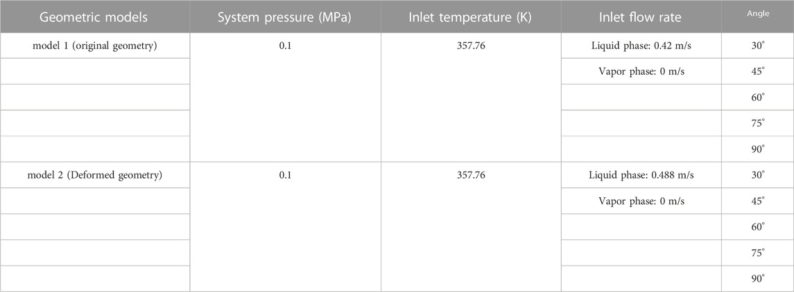
TABLE 4. Calculation boundary.
It can be seen from the results that the predicted CHF values at different angles of the original geometry flow channel increase with the increase of the angle, and the same trend appears in the deformed geometry. Compared with the original geometric flow channel, the CHF predicted value at the local position of the deformed geometry is significantly lower.
From the results, it can be seen that the predicted CHF values at different angles of the original geometry flow channel increase with increasing angle, and the same trend occurs in the deformed geometry. Compared with the original geometry flow channel, the CHF prediction at the local position of the deformed geometry is significantly lower.
Predicted values of CHF at different angles within the four different geometric flow channels are shown in Table 5. The deviation of CHF at different positions of the deformed channel from the original geometry is also given in the table.
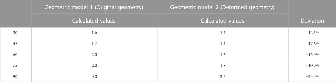
TABLE 5. CHF value prediction table.
The inlet and outlet area of the cooling channel is the main factor affecting the natural circulation, and the decrease of inlet and outlet area caused by the channel deformation will lead to the CHF decrease. From the table, it can be seen that the predicted values of CHF at different angular positions of the deformed flow channel geometry model are lower compared with the original geometric flow channel, which are reduced by about 13%–25%. This is due to the reduction of the cross-sectional area of the external flow channel of the lower head caused by the solid creep deformation of the lower head. With the identical meshing strategy and cross-sectional mesh parameters, the mesh volume near the near-wall surface of the deformed geometric flow channel decreases and the heat absorbed by the void fraction is reduced.
4 Summary
In this study, a program based on the commercial CFD software FLUENT was developed that can be used for the boiling heat transfer characteristics analysis of two- phase flow in the external flow channel of the lower head. A four-equation drift flow model and a mannimen drift velocity model were used to solve for the two-phase parameters, including the pressure, velocity, temperature and void fraction of the mixed phase. To accurately calculate the interaction between the two phases, the program adopts the interphase mass, momentum and energy exchange models. Considering the existence of warming and phase change process of two-phase fluid in the boiling heat exchange process, the heat flux partition method was introduced, and the total heat flux was divided into single-phase convective heat exchange heat flux and evaporative heat flux, which are used for heating mixed-phase fluid and liquid-phase evaporation, respectively. To achieve the division of the total heat flux into two parts, the wall heat flux was first converted into a volume heat source in the first grid layer near the wall surface, and then an iterative algorithm was used to solve for the wall surface temperature, and then the heat flow share of each part can be calculated, so as to obtain the amount of vaporized steam on the wall surface. During the solution process, the dichotomous method is used to iterate the wall temperature.
Numerical simulations of the critical heat flux experiments for the external flow channel of the pressure vessel lower head were performed by using the developed model, and the CHF values for the corresponding operating conditions were obtained by using the method of gradually increasing the heat flux. Based on the calculated results, the following conclusions are drawn.
1) In this study, a two-phase flow boiling heat transfer characteristics analysis program based on the drift flow model was developed, which can be used to calculate the CHF characteristics in the external flow channel of the lower head of the pressure vessel.
2) The predicted value of the local CHF in the flow channel increases with the increase of the angle;
3) The predicted values of CHF in the deformed channel were reduced by 15%–25% compared with these in the channel without deformation.
Data availability statement
The raw data supporting the conclusion of this article will be made available by the authors, without undue reservation.
Author contributions
SW was responsible for the conceptual design and drafting of the paper; XG was responsible for drafting the paper and collecting data; RZ was responsible for drafting the paper and collecting data; BJ was responsible for drafting the paper and collecting data; JJ was responsible for making important revisions to the paper; FL was responsible for making important revisions to the paper; XT was responsible for making important revisions and approving the final version of the paper for publication.
Funding
Support by National Key Research and Development Program (No. 2019YFB1900701).
Conflict of interest
The authors declare that the research was conducted in the absence of any commercial or financial relationships that could be construed as a potential conflict of interest.
Publisher’s note
All claims expressed in this article are solely those of the authors and do not necessarily represent those of their affiliated organizations, or those of the publisher, the editors and the reviewers. Any product that may be evaluated in this article, or claim that may be made by its manufacturer, is not guaranteed or endorsed by the publisher.
References
Chu, T., Bentz, J., Slezak, S., and Pasedag, W. F. (1997). Ex-vessel boiling experiments: Laboratory- and reactor-scale testing of the flooded cavity concept for in-vessel core retention Part II: Reactor-scale boiling experiments of the flooded cavity concept for in-vessel core retention. Nucl. Eng. Des. 169 (1), 89–99. doi:10.1016/s0029-5493(96)01279-4
Esmaili, H., and Khatib-Rahbar, M. (2004). Analysis of in-vessel retention and ex-vessel fuel coolant interaction for AP1000[M]. Maryland, United States: US Nuclear Regulatory Commission.
Esmaili, H., and Khatib-Rahbar, M. (2005). Analysis of likelihood of lower head failure and ex-vessel fuel coolant interaction energetics for AP1000. Nucl. Eng. Des. 235 (15), 1583–1605. doi:10.1016/j.nucengdes.2005.02.003
Jamet, M., Lavieville, J., Atkhen, K., and Mechitoua, N. (2015). Validation of NEPTUNE_CFD on ULPU-V experiments. Nucl. Eng. Des. 293, 468–475. doi:10.1016/j.nucengdes.2015.07.004
Kang, K.-H., Park, R.-J., Kim, S.-B., Kim, H.-D., and Chang, S.-H. (2006). Flow analyses using RELAP5/MOD3 code for OPR1000 under the external reactor vessel cooling. Ann. Nucl. energy 33 (11), 966–974. doi:10.1016/j.anucene.2006.06.003
Khatib-Rahbar, M., Esmaili, H., Vijaykumar, R., and Wagage, H. (1996). An assessment of ex-vessel steam explosions in the AP600 advanced pressurized water reactor[J]. ERI/NRC: Energy Research, Inc., 95–211.
Lavieville, J., Quemerais, E., Mimouni, S., Boucker, M., and Mechitoua, N. (2005). NEPTUNE CFD V1.0 theory manual. Paris, France: EDF.
Park, R., Ha, K., Kim, S., and Kim, H. (2006). Two-phase natural circulation flow of air and water in a reactor cavity model under an external vessel cooling during a severe accident. Nucl. Eng. Des. 236 (23), 2424–2430. doi:10.1016/j.nucengdes.2006.03.006
Rempe, J., Knudson, D., Allison, C., Thinnes, G., and Atwood, C. (1997). Potential for AP600 in-vessel retention through ex-vessel flooding[R]. Idaho Falls, ID (United States): Lockheed Idaho Technologies Co., Idaho National Engineering and Environmental Lab.
Rempe, J., and Knudson, D. (2004). Margin for in-vessel retention in the apr1400–VESTA and SCDAP/RELAP5-3D analyses[J]. United States: Idaho National Engineering and Environmental Laboratory Bechtel BWXT Idaho.
Rempe, J. L., Condie, K. G., Knudson, D. L., Suh, K. Y., Cheung, F. B., and Kim, S. B. (2005). Development of an enhanced core catcher for improving in-vessel retention margins. Nucl. Technol. 152, 170–182. INEEL/JOU-04-01983). doi:10.13182/nt05-a3668
Rempe, J., Suh, K., Cheung, F., and Kim, S. In-vessel retention strategy for high power reactors[J]. Final Report, Idaho National Engineering and Environmental Laboratory, Report No. INEEL/EXT-04-02561, 2003.
Rouge, S. (1997). SULTAN test facility for large-scale vessel coolability in natural convection at low pressure. Nucl. Eng. Des. 169 (1), 185–195. doi:10.1016/s0029-5493(96)01277-0
Teng, H. U., Chang, H. J., and Xue, Y. F. (2018). Experimental studies of the CAP1400 IVR strategy[J]. China: China Nuclear Power.
Theofanous, T., Liu, C., Additon, S., Angelini, S., Kymäläinen, O., and Salmassi, T. (1997). In-vessel coolability and retention of a core melt. Nucl. Eng. Des. 169 (1), 1–48. doi:10.1016/s0029-5493(97)00009-5
Theofanous, T., Oh, S., and Scobel, J. (2004). In-vessel retention technology development and use for advanced PWR designs in the USA and Korea[R]. Santa Barbara (US): The Regents of The University of California.
Weisman, J., and Pei, B. S. (1983). Prediction of critical heat flux in flow boiling at low qualities. Int. J. Heat. Mass Transf. 26 (10), 1463–1477. doi:10.1016/s0017-9310(83)80047-7
Wen, Q. L., Chen, J., Lu, D. H., and Zhou, H. (2012). Visual experimental study on bubble behavior on inclined downward facing surfaces[J]. Nucl. Power Engs 33 (03), 51–55. doi:10.3969/j.issn.0258-0926.2012.03.011
Yang, Z., Su, G. H., Tian, W. X., and Qiu, S. (2011). Theoretical study on critical heat flux for reactor lower head using subscale boundary layer boiling model [J]. China: Hedongli Gongcheng/Nuclear Power Engineering.
Yong-chun, L., and Yan-hua, Y. (2010). Non-heating experimental study on external reactor vessel cooling [J]. Nucl. Power Eng. 22 (31), 53–56. doi:10.3969/j.issn.0258-0926.2012.s1.013
Keywords: IVR, CHF, CFD analysis, RPV, coolant channel
Citation: Wen S, Gao X, Zhang R, Fan K, Jia B, Jing J, Liu F and Tian X (2023) Study on the influences of RPV deformation on CHF under IVR conditions. Front. Energy Res. 11:1087135. doi: 10.3389/fenrg.2023.1087135
Received: 02 November 2022; Accepted: 30 January 2023;
Published: 09 February 2023.
Edited by:
Jun Wang, University of Wisconsin-Madison, United StatesReviewed by:
Chenglong Wang, Xi’an Jiaotong University, ChinaLaishun Wang, Sino-French School of Nuclear Engineering and Technology, Sun Yat-sen University, China
Yinan Cai, Massachusetts Institute of Technology, United States
Copyright © 2023 Wen, Gao, Zhang, Fan, Jia, Jing, Liu and Tian. This is an open-access article distributed under the terms of the Creative Commons Attribution License (CC BY). The use, distribution or reproduction in other forums is permitted, provided the original author(s) and the copyright owner(s) are credited and that the original publication in this journal is cited, in accordance with accepted academic practice. No use, distribution or reproduction is permitted which does not comply with these terms.
*Correspondence: Xinlu Tian, eGlubHU3MjRAMTYzLmNvbQ==