 G. V. Brahmendra Kumar
 K. Palanisamy
95% of researchers rate our articles as excellent or good
Learn more about the work of our research integrity team to safeguard the quality of each article we publish.
Find out more
ORIGINAL RESEARCH article
Front. Energy Res. , 28 October 2022
Sec. Solar Energy
Volume 10 - 2022 | https://doi.org/10.3389/fenrg.2022.995034
This article is part of the Research Topic Solar Photovoltaic System to Meet the Sustainable Development Goals View all 9 articles
This paper proposes a ramp-rate control approach for a grid-connected MG with a hybrid energy storage system. Distributed energy sources (DERs), such as solar photovoltaic (PV) and wind, combined with energy storage (ES) and controllable loads, are critical to a power grid that can handle the intermittent nature of renewable energy sources. Therefore, the complexity of the system is increasing as researchers move towards a more renewable based power grid. An energy management system (EMS) for microgrids must consider the power available in RESs as well as the storage capacity of energy storage devices (ESSs). Modern MGs include a wide range of converters for a variety of applications, including distributed generation interconnection, grid integration, energy storage management systems, and demand management, among others. So, the ramp-rate control smooths fluctuations in photovoltaic power, which increases system reliability. In the proposed system, 80 V DC is used to supply high and low power DC loads. The suggested system can extract the maximum amount of energy from RESs, maintain efficient ESS management, and achieves quick DC-link voltage regulation with settling time of 230 ms throughout all operating modes. These conditions are met by the energy management system, which gives the MG with operational capability and ensures its reliability. The MG with proposed features and EMS was validated using the MATLAB/Simulink environment, and results were obtained using the Hardware-in-the-Loop (HIL) experimental test bench. The proposed small-scale RES-based MG can be used to develop and test algorithms for a wide range of MG applications.
Current power grids are struggling to cope with the increasing electricity demand. A MG interconnected RESs and loads have emerged as an attractive alternative to traditional fossil fuel-based power generation to reduce operational and environmental costs (Brahmendra Kumar and Palanisamy, 2019). On the other hand, renewable energy is sporadic in nature. Therefore, MGs cannot be relied upon to function continuously (Zia et al., 2018).
As a result of this problem, several solutions have been proposed. MGs, for example, may be permanently linked to the main grid to compensate for any energy shortfalls. This initiative is not environmentally friendly and may lead to higher energy costs for MGs, as any energy deficit should be mitigated by obtaining conventional power from the main grid despite high electricity prices of the main grid. Moreover, storage systems can be used in combination with RES to store excess energy, which can be released when demand is low or when the price of electricity from the main grid is high (Yi et al., 2017). However, it is not a good practice to rely solely on ESSs due to their limited capacity, high maintenance costs, and losses during the charging and discharging processes.
There have been many changes in smart grid technology over the past few years, and one of them is energy cooperation between MGs, which has been suggested as a new way to implement MGs more reliably and at a lower cost (Gundumalla and Eswararao, 2018). Energy cooperation allows MGs to share power with those with surplus power. Then, it is important to ensure that the amount of energy each MG draws from the main grid, the amount each MG charges and the amount it discharges from the ESS, all work together (Sahoo et al., 2018). This means that MGs must work together to improve their energy management.
The most common hybrid RES are solar and wind power. A variety of control techniques are used to ensure efficient transfer of power in hybrid RESs. Energy conversion systems and converters used at different locations in the entire energy system affect the system design, which requires a lot of interest and research in this area (Kumar and Palanisamy, 2020). A PV-battery based hybrid MG system is proposed in (Yi et al., 2017). In this, the BS balances the power between the DC link and the AC link under all conditions, which places additional strain on the BS. Hence, the system cost increases to handle peak demand and battery life is shortened. In (Anilkumar et al., 2020), various load demand profiles and weather data were analyzed to evaluate the performance of a hybrid energy system. It discussed irradiation changes based on atmospheric conditions and effects on PV power profile. Improve DC grid voltage regulation for standalone DC MGs with battery and SC as discussed in (Sathishkumar et al., 2012; Kumar et al., 2020). But more settling time is required to restore a constant DC link voltage when the load changes.
In (Ouammi et al., 2015; Wang et al., 2015; Mahmood and Jiang, 2019; Fu et al., 2022), a single MG or a group of MGs operating independently of each other were studied. These studies focus on the off-line EMS problem by assuming that RES generation and load demand are deterministic or known in advance. Stochastic RES generation and load models were used to solve the online EMS problem. But these do not take into account the PV power variations on a time basis. Hence, the power consumption from the battery is high and the change in voltage is also high. EMS between multiple MGs has been examined in (Wang et al., 2016a; Wang et al., 2016b; Rahbar et al., 2018). In this method, failure to consider the minimum and maximum ESS limits may render their results practically unenforceable. RES/load generation must have a stable process or precise distribution, which may not be possible for highly intermittent RES such as solar and wind. A coordinated control strategy for PV and ESSs is proposed in (Wu et al., 2015) considering the available power in RES and ESS SoC conditions. However, this algorithm requires additional control schemes to coordinate with the distributed MG elements connected on the AC bus side of the DC link to work. As a result, a wide range of power conditions from distributed RES and storage capacity from ESS must be considered globally to ensure that MGs are flexible and reliable. A power smoothing method for a large-scale PV plant is presented in (Wang et al., 2014). Due to the dynamic nature of modern MGs, it is impossible for the DC link voltage to be constant. The DC link voltage is affected by any power imbalance or fluctuation, and it is difficult to maintain the power balance and stability of the MG. ESS for renewable-grid integration of PV smoothing control is described in (Brahmendra Kumar et al., 2018). The batteries in this system must be able to handle any fluctuations in the DC link voltage due to changes in load or solar power generation. Consequently, the BS is subjected to high current stress, which shortens its lifetime.
Several important studies on this topic have been reported in the literature (Tummuru et al., 2015a; Tummuru et al., 2015b; Karimi et al., 2017; Manandhar et al., 2019; Xu et al., 2020; Hosseini et al., 2021; Jiang et al., 2021; Li et al., 2022). However, these studies have focused on isolated situations with DC link for RES-grid connected HESS or DG resources. Flexible operation of DC MG with HESS is proposed in (Tummuru et al., 2015a). However, more time is required for settling and computation in order to keep the DC link voltage stable. In (Hosseini et al., 2021), a unique EMS for grid-connected residential MG with ESS is proposed. However, the island operation of MG is not considered and is a very crucial part of the residential sector. In (Tummuru et al., 2015b; Manandhar et al., 2019), HESS and its EMS are described in detail. But this method can cause a drastic increase in battery charge and discharge rates produced during the transition, resulting in a decrease in battery life. These methods provide more settling time and the maximum overshoot is also higher. In MG management systems, a coordinated SoC control strategy is implemented to stabilize the bus frequency and voltage amplitude of MGs based on a model predictive control algorithm for DG and ESS units. If one communication link fails, the whole system is out of synchronization, so ESS and RES are coordinated by centralized management control (Li et al., 2022). According to the EMS proposed in (Xu et al., 2020), power can be injected or withdrawn from the grid based on changes in DC and AC load and changes in RES power. However, the grid operating conditions and charging conditions of the ESS are not taken into account. There is a dearth of details on off-MPPT and load shedding activities. In addition (Jiang et al., 2021), proposed an advanced control algorithm. Flexible demand sharing is considered in the proposed control strategy to achieve decentralized MG coordination, but more communication links and computational time are still required.
To avoid the use of external communication links, researchers have examined autonomous control methods for power distribution. For power management, AC/DC power lines have been proposed as communication channels (Karimi et al., 2017). Some high-frequency components are used in power line communication carriers to develop coordinated control strategies in (Alramlawi and Li, 2020), (Neto et al., 2018), but this introduces noise and the signal bandwidth must be designed carefully. Droop control regulates the output voltage and frequency of the DG unit to provide optimal active and reactive power sharing in AC MGs (Rosero et al., 2020). As a result, since most RES at MPP are controlled in power control mode (PCM), conventional droop methods for power management cannot be directly implemented in systems integrating RES and ESS. Furthermore, an adaptive droop control approach is proposed in (Li et al., 2021) for MGs operating in grid/isolated mode. This approach is based on the all-DG-droop approach, but the different core source conditions of the DG units are not taken into account.
The variable power generation and load demand are a challenge that can be efficiently and successfully addressed by a HESS that relies on BSs and SCs. The BS and SC lifespans can be greatly improved by avoiding overcharging and over discharging. In order to keep ESSs within their optimal performance range, prevent them from being damaged by overcharging or discharging. Hence, an efficient energy management system (EMS) is required. Based on the above shortcomings, a smoothing control based efficient EMS for MG with HESS is proposed in this work. The primary objective of this study is to design and develop a RES-based MG system using RR control that can reduce power fluctuations and provide continuous power to the grid under different operational conditions with HESS. So, the EMS maintains the power balance in the MG and provides flexible and configurable control for various RES and load demand changes.
The main features of the proposed work are:
i) PV power fluctuations are mitigated using RR control, which provides continuous operation of the system and improves system reliability.
ii) The obtained battery power is measured by limiting the PV power, which is the difference between the original PV power and the ramp-rate PV power by the RR controller. Therefore, the power consumption of the ESS depends upon the rise or fall rate of the PV power fluctuations.
iii) It limits the charge and discharge rates of the BS and SC.
iv) The recovery time of voltage is very low and achieves quick DC link voltage regulation.
v) reducing stress on the BS pack and increasing system life.
vi) Improvements in power quality at the PCC.
vii) Seamless power transfer between various grid and islanded connected modes and vice versa.
HIL prototyping can be used to test the proposed system in a real-time environment. An efficient renewable energy management system can be developed using this test bench to validate control algorithms in real time.
The organization of the paper is as follows: Section 2 describes the configuration and EMS of the proposed system. Section 3 discusses stability analysis and control of HESS. Section 4 presents the simulation results and discussion, and Section 5 explains the HIL implementation and results. Section 6 describes the conclusion.
The renewable-grid connected MG with HESS is depicted in Figure 1. It comprises PV system with a single-stage inverter linked to the utility grid using a common DC-link. The BS and SC are connected to a common DC-link with two bidirectional buck-boost converters. During excess (EPM) or deficit mode (DPM), the BS provides or absorbs power, respectively. Surges in PV and load power are delivered/absorbed by SC. In addition, the SC unit reduces BS and grid stress by adjusting peak currents.
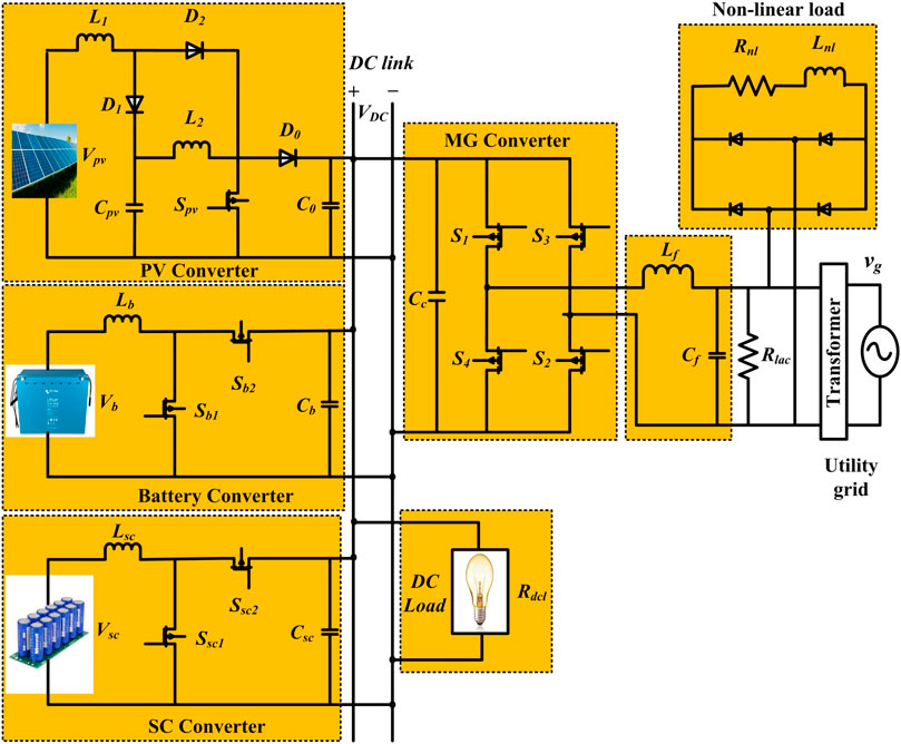
FIGURE 1. Proposed renewable-grid connected MG.
The output of a PV system fluctuates significantly due to the irregular nature of solar energy due to climatic conditions. The maximum decrease/increase in PV generation on a cloudy or windy day is determined by the wind speed and the size of the PV plant. When clouds are moving quickly, PV output decreases significantly. Thus, the injection of PV energy into a distribution grid creates issues with power quality such as voltage variations, stability deprivation, etc. PV power variations are not severe under normal climate conditions, but severe climate conditions account for 70–90% of all PV power fluctuations (see Figure 2A). It is probable to alleviate these power quality issues by using an efficient ESS (Brahmendra Kumar et al., 2018). In order to smooth out the output of the PV, the BS can be used with RR control. The RR control is a method of limiting the rate of power change from the PV system in order to maintain grid stability. The battery power characteristics are presented in Figure 2B based on RR control. The area around the green line shows the minimum and maximum energy capacity of the battery that is needed to effectively smooth the variation in PV output.
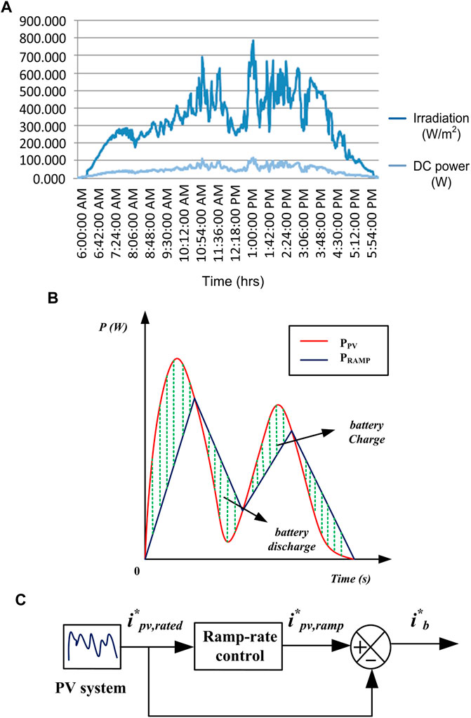
FIGURE 2. (A) Irradiation profile on a day (Kumar et al., 2020). (B) Battery power characteristics based on RR control (Kumar et al., 2020). (C) Ramp-rate control model diagram.
Figure 2C Depicts a block diagram for a basic RR control system. The rate of rise/fall is limited to a maximum RR (rmax) value denoted as RES-RR. The maximum RR value that can be considered is 10%/min.
The difference between rated PV power (
As illustrated in Figure 3, the EMS control parameters balances power between RES, grid and ESS. This algorithm takes into account the present state of Ppv, Pl, SoCb, SoCsc, Ib, and Isc as input parameters. The algorithm starts with input parameters and secondly, the algorithm considers these variables to decide the operation mode of MG (i.e., RES balances or less or more than the load demand). The BS and SC status of SoCs is analyzed in the third stage, i.e., whether SoCb and SoCsc are within or above the SoCH or SoCL limits. Finally, different BS and SC reference conditions and preferences are determined by various grid-interactive states that decide the MG-VSC reference, such as grid sharing, grid injection or idle mode, and also by BS and SC charging and discharging, or both charging and discharging, or both being in idle conditions. By limiting SoCb and SoCsc to safe levels, this technique considers the ESS’s energy content and limits active involvement to its rating.

FIGURE 3. Control parameters for EMS.
The EMS and converter control are shown in Figure 4 as a simplified control scheme for this proposed system. The reference currents for the BS, SC, and MG-VSC converters are generated according to the scheme shown in Figure 5. To generate the error signal, a comparison is made between the actual (i.e., ipv, ib, isc, ig) and reference currents in the current controller. The BS, SC, and RES-based converters rely on the modular signals generated by PI controllers for input. A hysteresis current controller regulates the MG-VSC’s switching pulses.
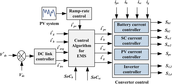
FIGURE 4. Simplified control of a proposed system.

FIGURE 5. Overall proposed control system configuration.
A constant DC-link voltage maintains system power balance (Neto et al., 2018). A DC-link controller generates a net current (i*dc) that is either injected or drawn from the DC-link. A PI controller processes this signal to generate the net current (i*dc), which is shown in Figure 6. The voltage control loop written in (4) is used to calculate the total current, inet(t). The HESS and the utility grid must sustain power balance by dividing the inet into average (iavg) and transient (itrs) components, respectively.
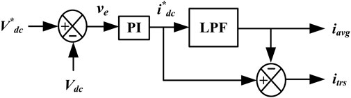
FIGURE 6. DC-link voltage controller.
The DC-link power (Pdc) is taken by,
Where kp and ki are the PI controller’s proportional and integral components, and τc is the low-pass filter time constant. The control structure and power balance at the DC-link are illustrated in Figure 5 and the equation is as follows:
Where Ppv, Pg, Phess, Pdcl, and Pacl are PV, grid, HESS, DC and AC load powers, respectively.
It operates in two modes: 1) excess power (EPM: PH > 0) and (ii) deficit power (DPM: PH≤ 0) modes. Two operating modes are considered depending on the availability of RES power generation and system load requirements. The balance equation for EPM and DPM is PH = Pb + Psc + Pg = Pdcl + Pacl - Ppv. As illustrated in flowchart Figure 7, the system works in various modes of operation depending on the condition of PH. As shown in Tables 1A,B, DPM and EPM distinguish four distinct operating modes based on the conditions of the SoCb and the SoCsc.
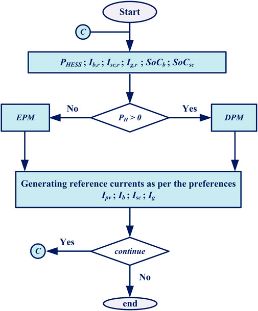
FIGURE 7. Conditions of the proposed EMS.
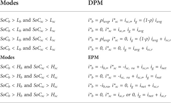
TABLE 1. A DPM. B EPM.
An important part of BS-based devices is the State of charge (SoC), which also improves BS performance. The BS can be protected, overcharging can be prevented, its lifetime can be extended, and the system’s accuracy can be improved with proper SoC calculations (Hosseini et al., 2021). The SoC of BS and SC is calculated using the count-coulomb approach and the resulting equations are given by,
The current i(t) is measured and integrated over time to calculate the amount of energy that remains in the battery and SC. SoC helps to analyse battery and SC whether to charge or stop charging. This approach relies on exact measurements of battery and SC current and initial SoC. Where SoCbin and SoCscin are the BS and SC initial SoCs, CNb, and CNsc are the BS and SC nominal capacitances, and ib and isc are the BS and SC currents.
The operational objectives defined for DPM are discussed in the following sections.
State I: Discharging both the BS and SC is necessary if SOCb > Lb and SOCsc > Lsc. The BS, SC, and grid settings are set to the following,
ρ represents the charging and discharging condition of the BS. Table 2 contains the results of a four-state logic used to determine the value of ρ.
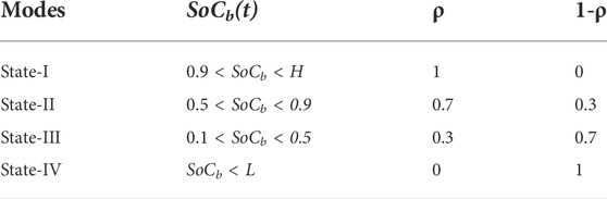
TABLE 2. Charge/discharge coefficient (ρ).
State II: The BS should be idle if SoCb < Lb and SoCsc > Lsc. SC provides transient and oscillatory current while the grid meets average power demand.
State III: The SC should be idle if SoCb > Lb and SoCsc < Lsc, and the BS is discharged until SoCb reached Lb to meet the average power demand while the SC is idle or charged from the grid. The grid supplies the required SC and average power demand.
State IV: When SOCb < Lb and SOCsc < Lsc, the BS and SC are idle or charged by the utility grid. The grid is able to handle the total difference between generation and load power requirements.
In this case, the grid supplies both average and transient power demand.
As the charge/discharge cycles of the SC are much faster than the battery, the PI controllers are adjusted to the corresponding SC power stage. When using SC, the BW of the inner CCL is set at fsw/6. The BW of battery is kept lower than SC current loop BW (fsw/10) to redirect the fast-changing transient to the SC (Kollimalla et al., 2014). The gain H is considered to be one for all converters. Table 3 lists the variables for the converters considered in the calculation part of the equations below.

TABLE 3. System parameters.
The battery controller block diagram is presented in Figure 8. The TF of control to inductor current is taken as (Kollimalla et al., 2014),
FIGURE 8. Battery CCL block diagram.
The TF of CCL compensator is as follows:
The OLTF of CCL is given by,
The Bode plot of the OLTF for the battery is depicted in Figure 9. To develop and optimize the control parameters, the SISO tool is used. The PI controller is calibrated to obtain a PM of 60° at rate of 1.97 krad/s. The calculated Db, Kpb and Kib parameters are 0.4, 0.1 and 11, respectively.
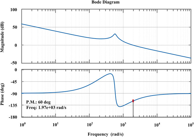
FIGURE 9. Bode plot of CCL for battery.
The SC controller block diagram is presented in Figure 10. The TF of control to inductor current is taken as (Kollimalla et al., 2014),
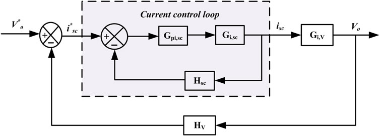
FIGURE 10. SC CCL block diagram.
The TF of CCL compensator is as follows:
The OLTF of CCL is given by,
The Bode plot of OLTF for SC is depicted in Figure 11. The PI controller is calibrated to obtain a PM of 60° at rate of 6.43 krad/s. The calculated Ds, Kpsc and Kisc parameters are 0.6, 0.56 and 120, respectively.
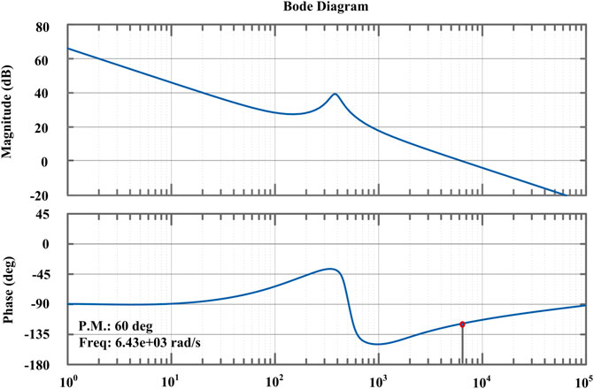
FIGURE 11. Bode plot of CCL for SC.
The TF of VCL is taken as (Kollimalla et al., 2014),
The TF of VCL compensator is as follows:
The OLTF of VCL is given by,
The Bode plot of the OLTF for the voltage controller is depicted in Figure 12. The PI controller is calibrated to obtain a PM of 60° at rate of 0.2 krad/s. The calculated Ds, KpV and KiV parameters are 0.6, 0.23 and 15, respectively.
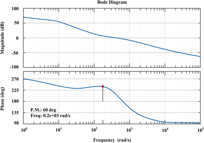
FIGURE 12. Bode plot of VCL for HESS.
The MATLAB/Simulink environment has been used to test the validity of the proposed system. Table 3 lists the proposed system parameters. According to the SoC status ESS in Figure 13 and Figure 14, four different operating modes are shown in this section.

FIGURE 13. (A) DC-bus voltage, (B) PV, (C) BS, (D) SC, (E) DC load, (F) grid, and (G) VSC currents.
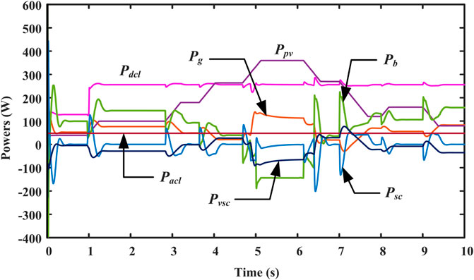
FIGURE 14. Various power results.
Under DPM, this power mode has four defined states of operation modes based on the SoC status of the ESDs.
State-1 (SoCb > L and SoCsc > L): In Figure 14, the BS and grid power share the deficit load power (Pdeficit) up to SoCb < L. At t = 1s, the SC pack produces an instant variation in the Pdcl. This state provides quick DC-link voltage control and smooth operation of the BS, as shown in Figure 13A and Figure 13C.
State-2 (SoCb < L and SoCsc > L): The Pb reference is set to zero in Figure 14. Thus, the grid provides the entire deficit power under a steady-state condition, while SC removes the sudden power variations at t = t0. In Figure 13G, ivsc achieves a smooth transition.
State-3 (SoCb > L and SoCsc < L): At t = t1, the BS and grid share the Pdeficit until SoCb < L, as depicted in Figure 14.
State-4 (SoCb < L and SoCsc < L): At t = t2, total Pdeficit is provided by the utility grid. Figure 13A shows the DC-link voltage, whereas Figures 13C-G show the respective changes in BS, SC, DC load, grid and VSC currents.
Under EPM: This mode charges the ESDs with extra power from RES until it reaches its maximum SoC limits. The VSC then supplies additional power to the grid. The various power outcomes of the system are illustrated in Figure 14.
Figure 13B shows the PV current profile under different operating modes, as the system transitions from one mode to another depending on the available RES and load power circumstances. During abrupt variations in PV and/or load, the SC provide/absorb transient power. The ipv is generated at t3-t4 instants lower than the load requirement. So, the system works in DPM mode with the BS and the utility grid sharing the Pdeficit. During t4-t5, ipv exceeds the load demand. This results in the system running in EPM mode, with the excess power mainly used to recharge the ESSs. In the t5-t6 instants, ipv is once again below the load requirement. Thus, the system works in DPM. Smooth changes in ib, ig and ivsc are seen during the transition phase, as shown in Figure 13C, Figure 13F,G.
The ivsc is depicted in Figures 15A as the DC load varies. At t = 1s, the idc has increased, and the VSC uses grid power to supply the increased DC demand. Figures 15B–D depict the power quality characteristics of the proposed system. The non-linearity in AC load increases at t = 9s in Figure 15B and the VSC provides harmonic elements for the load, as illustrated in Figure 15C. Therefore, unity power factor (UPF) can be achieved on the grid as a result of stable ig, as illustrated in Figure 15D. Harmonic and reactive load current elements are supplied by MG-VSC in this system to run the utility system at UPF.
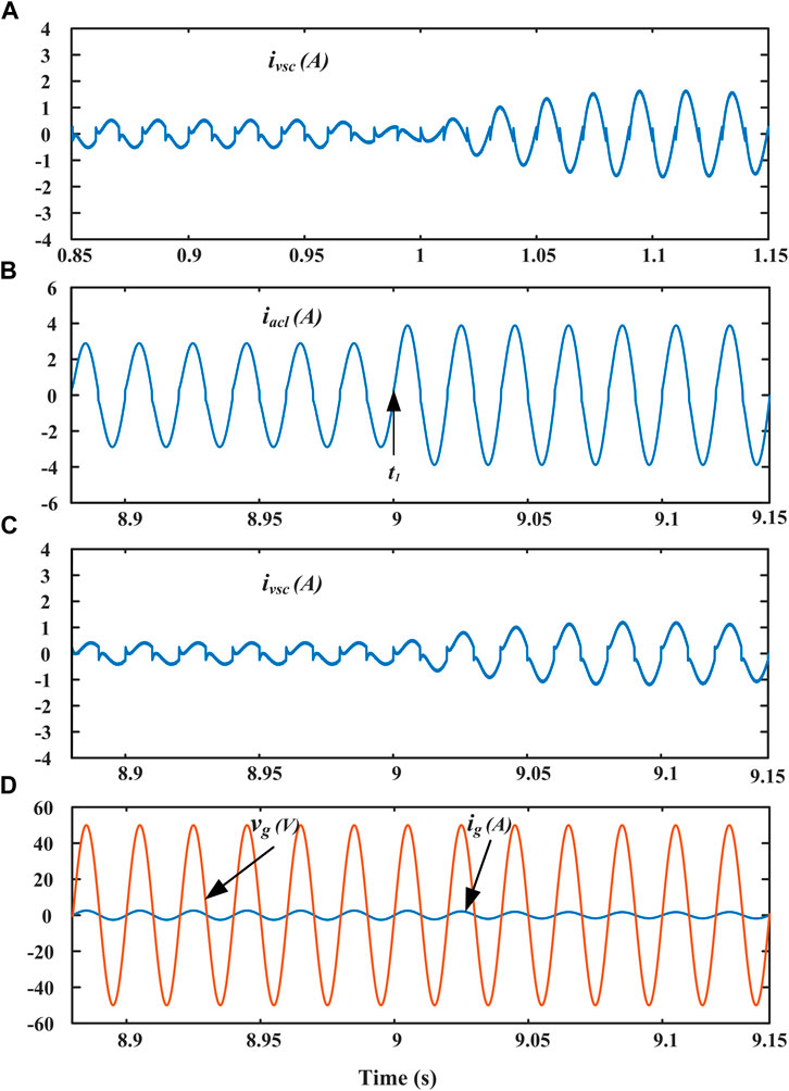
FIGURE 15. Features of power quality of the proposed system.
The OP5700 HIL testbed setup is used to validate the proposed system as shown in Figure 16. In HIL setup, RT-LAB, PCB-E06-0560, LAN network, MSOX3014T probes, and connecting wires are all used. Analog outputs and digital inputs on the PCB can be utilized to exchange data between the simulation and real controller. The proposed EMS operates in various power modes depending on the PH value. Figure 13 illustrates the ESS, grid currents, and DC link voltage when PH is less than zero (DPM) and greater than zero (EPM). In each power mode, the states of the ESSs change in accordance with the respective SoCs.
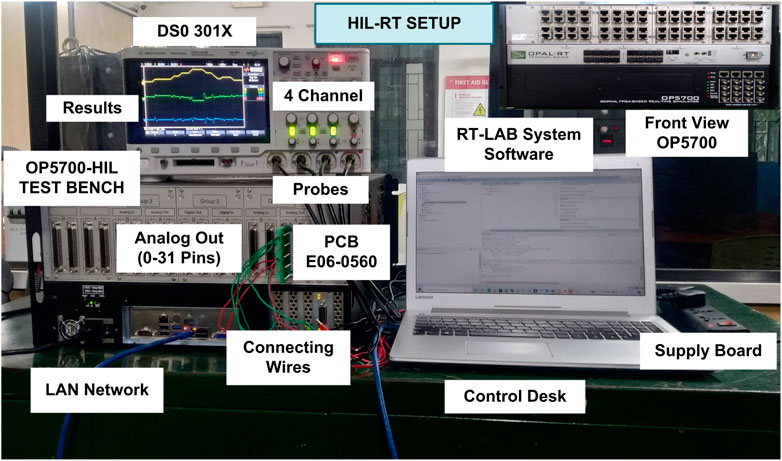
FIGURE 16. HIL experimental testbed.
The scale of the figures presented in Figures 17, 18, 19, the X-axis represents the time per division (s/div) and the Y-axis represents the current (A/div), voltage (V/div), and power (W/div) values per division. Figures 17A–H illustrates the performance of the EMS during EPM operation. In this mode, the generation exceeds load demand by a predetermined margin.

FIGURE 17. (A) HIL results: (a) PV, (b) BS, and (c) SC currents. (B) HIL results: (a) DC-link voltage, (b) DC load current. (C) HIL results: (a) AC load, (b) grid, and (c) VSC currents. (D) HIL results: (a) constant AC load, (b) VSC, and (c) grid currents. (E) HIL power results for PV, BS, SC, and DC load under EPM operation. (F) HIL power results for VSC, constant AC load and grid. (G) HIL power results for VSC, AC load, and grid. (H) HIL results: (a) VSC current, (b) AC load current, (c) grid current and voltage.

FIGURE 18. (A) HIL results: (a) PV, (b) BS, and (c) SC currents. (B) HIL results: (a) DC-link voltage, (b) DC load current. (C) HIL results: (a) AC load, (b) VSC, and (c) grid currents. (D) HIL results: (a) constant AC load, (b) grid, and (c) VSC currents. (E) HIL power results for PV, BS, SC, and DC load under DPM operation. (F) HIL power results for VSC, constant AC load and grid. (G) HIL power results for VSC, AC load and grid. (H) HIL results: grid current and grid voltage.
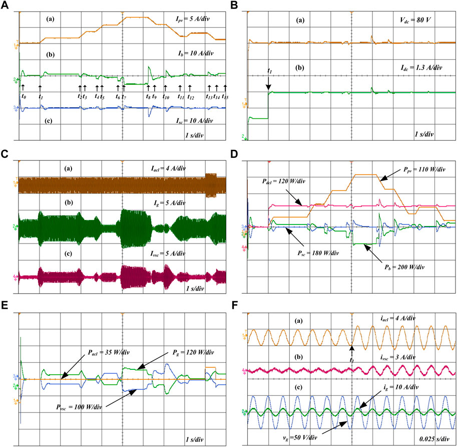
FIGURE 19. (A) HIL results: (a) PV, (c) BS, and (c) SC currents. (B) HIL results: (a) DC-link voltage, (b) DC load current. (C) HIL results: (a) AC load, (b) grid, and (c) VSC currents. (D) HIL power results for PV, BS, SC, and DC load under seamless mode of operation. (E) HIL power results for VSC, AC load, and grid. (F) (a) AC load current, (b) VSC current, and (c) grid current and grid voltage.
The PV current profile shown in Figure 17Aa. The response battery and SC current profiles are presented in Figure 17Ab,c. At time t1, SoCb and SoCsc are lower than H. Changes are made to the DC load at time t1 = 1s in Figure 17Bb, which results in a voltage deviation in the DC link. In this state, charge the BS and SC to their rated charging capacity and the SoC will attain its maximum value. The grid provides the required Pavg to sustain a stable DC link voltage in Figure 17Ba. The SC device provides transient power.
When SoCb reaches Hb at time t2, ib equals zero. The SC is charged at its rated current in this state because the SoCsc is still less than the Hsc. The SC is charged with a part of the surplus power, and the remaining surplus power being fed back into the grid.
At time t3, when SoCsc reaches Hsc, isc equals zero. After that, the BS is charged at its rated current until Hb is reached. The grid utilizes both transient and average power to sustain a stable DC link voltage during this condition in Figure 17Ba.
The At time t4, iacl has increased in Figure 17Ca. At this point, SoCsc is equal to Hsc and SoCb is lower than Hb. As a result, the charging current ib is constant and the transient power is delivered by the SC. The response of grid and VSC currents is illustrated in Figures 17Cb,c.
At time t5, SOCb and SOCsc are higher than H. In this state, the grid is able to stabilize the DC link voltage. The generation meets the total demand and surplus power is fed back into the grid. The ig and vg operate at unity power factor under all operating conditions. Figures 17D–G show the constant AC load, VSC, grid currents and various power results of PV, BS, SC, VSC, grid, DC and AC loads. Figures 17Ha-c show the inverter, AC load, grid currents, and grid voltage, respectively.
In this case, the ipv is less than the load demand, resulting in a PH < 0 and the PV current profile shown in Figure 18Aa remains constant. The SOCb and SOCsc thresholds are changed to observe the system behavior under extreme conditions. Hence, the controller and the proposed EMS can be studied under extreme operating circumstances.
Condition I: The Pdeficit shared by BS with the grid power until SoCb < L. The DC load is being changed from R = 50Ω–25 Ω at t1 in Figure 18Bb. As ib increases slowly in Figure 18Ab, the SC adjusts to the rapidly changing DC load power depicted in Figure 18Ac. Therefore, Vdc is quickly regulated in Figure 18Ba and ib changes smoothly as shown in Figure 18Ab.
Condition II: In this case, the SOCb is reduced. As a result, the grid supply deals with the active power demand under steady state, where the SC pack absorbs a transient change in power at t = t2. Therefore, ivsc achieves a smooth change at instant t2 in Figure 18Cb. The grid current response is shown in Figure 18Cc.
Condition III: SOCb is greater than Lb and SOCsc is less than Lsc. The BS and grid supply handle the deficit load power until SoCb < L.
Condition IV: Both SoCb and SoCsc are low in this condition. As a result, the grid provides the necessary power to sustain the Vdc at a stable level. In Figure 18Ca, the AC load increases at times t2 and t3. The SoCsc is now lower than Lsc. As a result, isc becomes zero. The ib gradually rises as the grid contributes to compensating the Pdeficit in the system and SC provides the transient change in power. Figures 18D–G show the constant AC load, grid, VSC currents and various power results of PV, BS, SC, VSC, grid, DC and AC loads. show the various power results of PV, BS, SC, VSC, grid, DC, and AC loads. Figure 18H shows the grid current and voltage, which are sinusoidal in nature.
Figure 19A depicts the proposed EMS dynamic performance in various operating modes based on variations in RES power. Figure 19Aa illustrates the high-gain RES converter with emulated RES current pattern applied to determine the feasibility of the proposed scheme. The ipv reduces the load demand between instants t0 and t7. Hence, the system works in DPM, sharing the available power between the BS and the utility grid. During the t7 and t8 instants, ipv exceeded the load demand. So, the system operates on EPM, and ESDs are charged with surplus power. Again, the ipv is lower than the load demand ranges from t8 to t15. Thus, the system runs on DPM as shown in Figure 19A. The smooth changes in ib, ig, and ivsc that occur during the mode transition are depicted in Figures 19Ab,Cb,Cc.
The power sharing between the seamless transfer operation modes is summarized in Table 4. Where CM: charging mode, DM: discharging mode, CG: charging from the grid, SL: load sharing, respectively. The results show that the high-power-density SC pack and its effective control of the DC link voltage significantly reduce the dynamics of the DC link voltage. The BS lifespan can be extended due to the reduced current stress due to reduced DC link voltage dynamics with the proposed EMS.
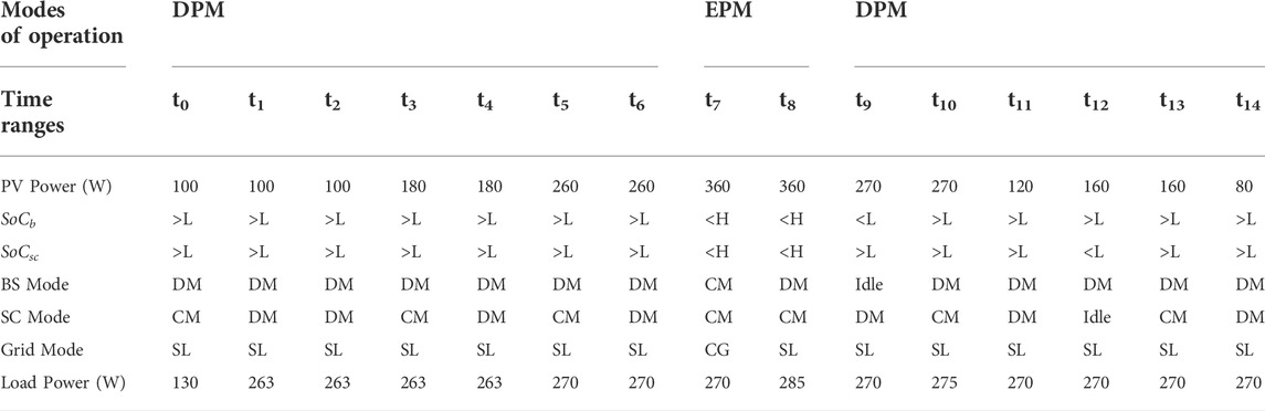
TABLE 4. Proposed EMS power changes in various operation modes.
As the DC load varies at t1 in Figure 19Bb, the PV generation also varies as illustrated in Figure 19Aa. At time t1, BS switches from a -1.2 A charging mode to +2.2 A discharging mode in response to varying load demand as shown in Figure 19Ab. As depicted in Figure 19Ac, the SC absorbs the transient power generated by the load and PV variation during the step change in load demand, thereby reducing BS stress. The ib gradually increases to compensate for the loss of low-frequency power. Hence, the BS endures less stress and the DC grid remains stable in Figure 19Ba. As can be seen in Figures 19D,E, the system dynamically switches between modes in response to the availability of RES power and current load conditions. The SC packs supply/absorb the transient power surges caused by rapid variations in RES and/or load, and the surplus average power generated in the DC link is utilised to charge ESDs or to inject into the utility grid, depending on the SoC of ESDs. The proposed EMS power quality features are illustrated in Figure 19F for various operating modes. When the VSC is not connected, ig has both fundamental and harmonic load current components. The nonlinear component of the AC load increases at t1 in Figure 19Ca and Figure 19Fa. A DC-AC inverter compensates for the non-linear component of an AC load. In addition to compensating current harmonics and reactive power, the VSC delivers and absorbs real power to and from the utility grid in Figure 19Fb. Therefore, ig in Figure 19Fc remains constant and the voltage and current of the AC grid are in phase. As a result, grid voltage and current are maintained with UPF. Figure 20A presents the harmonic spectra of iL and ig. A total harmonic distortion (THD) of 13.38% is measured on the current drawn by the non-linear load, while the current drawn by the grid is sinusoidal with a THD of 2.14% within the tolerances set by the IEEE-519 standard.
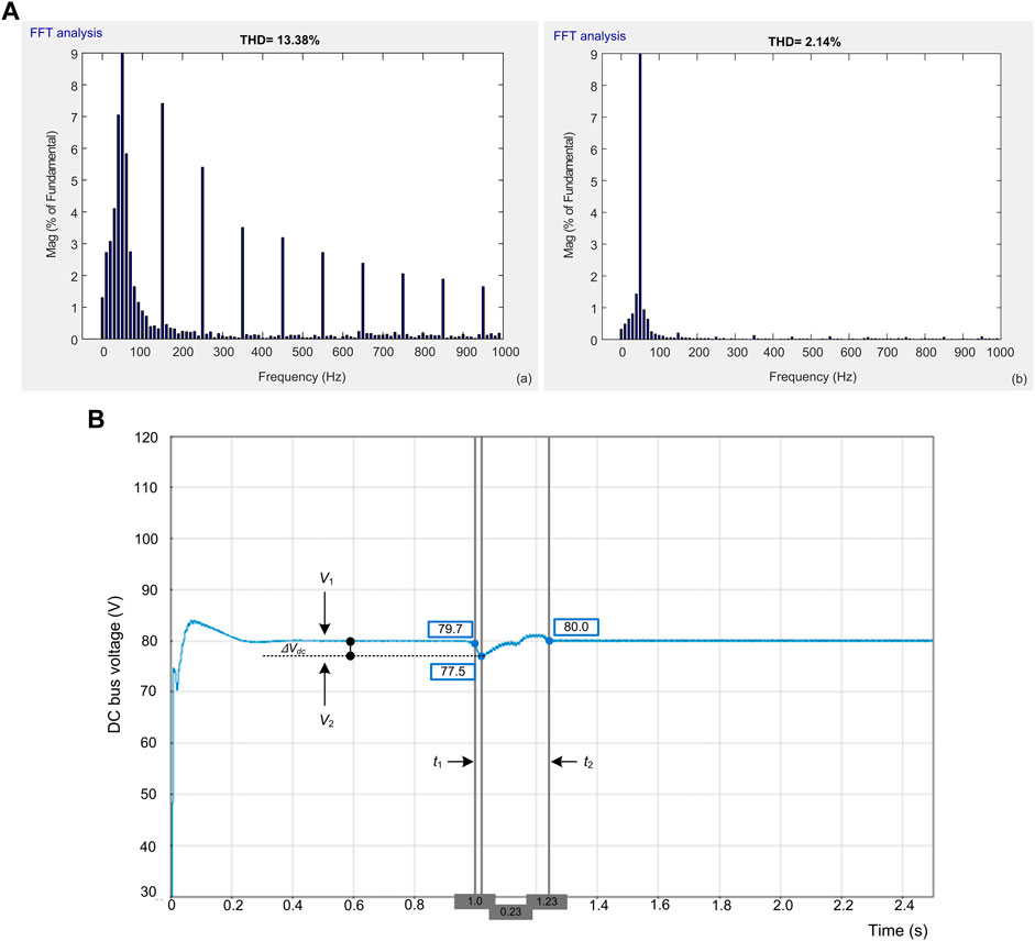
FIGURE 20. (A) THD analysis: (a) load current and (b) grid current. (B) Mp and Tr performance of DC bus voltage.
As illustrated at time t1 in Figure 19Ba, the results are used to analyse the voltage overshoot and the settling time that occurs with a step change in load demand. The voltage overshoot equation is as follows:
Figure 20B shows the change in voltage measured between V1 and V2 and the recovery time of voltage is measured between t1 and t2. The performance of the proposed system with the existing methods is presented in Table 5. Table 5 includes the peak overshoot (Mp), recovery time (Tr) of voltage, and grid THD compared to existing methods. Based on Table 5, the voltage overshoot is less and the DC link voltage requires less time to stabilise compared to the methods proposed in (Sathishkumar et al., 2012), (Manandhar et al., 2019), and (Tummuru et al., 2015b) techniques. Therefore, the proposed EMS provides less time to compute and has lower THD than existing methods.
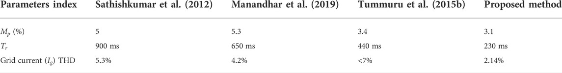
TABLE 5. Comparative analysis of the proposed system with existing methods.
An energy management strategy using ramp-rate control is proposed for a renewable grid-connected MG system with battery and supercapacitor as HESS. The effectiveness of the proposed strategy is demonstrated through the development and testing of a HIL setup. The main highlights are achieved using the proposed system mentioned below.
• Improved system reliability can be achieved by using ramp-rate control to smooth out fluctuations in PV power output.
• Since the amount of power generated from the battery depends on the ramp-rate control output, the charge/discharge rate of the battery to the controller is reduced and the power consumption of the battery is also reduced.
• Compared to existing methods, it achieves fast DC voltage regulation with a settling time of 230 ms.
• A grid-connected single-stage VSC can provide both current and voltage compensation.
• The SoC of ESSs ensures that all these characteristics are implemented within safe operating limits.
• HESS is used to assist both continuous and transient power applications. The purpose of SC device is also to minimize the current stress of BS and grid system.
• Also, the dynamic voltage compensation of the system is improved by SC, which also leads to an increase in system efficiency.
Therefore, the HIL experimental testbed results confirm that the proposed system can enhance local bus power quality under various conditions of PV, HESS, grid and loads. The controller enables efficient implementation of the EMS. There are numerous scenarios and control algorithms that can be tested using this test bench for research in the field of hybrid renewable energy MGs.
Due to their high costs and limited lifetime, future PV systems will rely heavily on ESS, which has a significant impact on the energy/economic balance of the PV system and plays a crucial role in the feasibility of PV systems in the future. Because of this, it is essential to carefully consider the ESS’s energy capacity, losses, and cyclical deterioration. It is clear that if both the amount of energy stored in an ESS and the number of times it is charged and discharged are reduced, the cost of installing and maintaining an ESS will be reduced. Therefore, choosing a control approach to minimize fluctuations will be a significant decision. The transition between modes must be considered when designing effective management strategies for reliable and continuous system operation. Future work involves incorporating control approaches and algorithms to improve power quality in grid-integrated MG systems using HESS. PV power can be smoothed using advanced smoothing control techniques. Large-scale power applications can use smoothing control to sustain stable power and improve system power quality. Advanced HESS control approaches can help RES producers and system operators in numerous ways.
The original contributions presented in the study are included in the article/supplementary material, further inquiries can be directed to the corresponding author.
Conceptualization, methodology, investigation, resources, data curation, writing—original draft preparation, GK; project administration, visualization, supervision, review, and editing, KP. Both authors have read and agreed to the published version of the manuscript.
This work was supported by the Department of Science and Technology (DST), Government of India (GOI) with the project grant SR/FST/ETI-420/2016(C) under FIST scheme.
The authors declare that the research was conducted in the absence of any commercial or financial relationships that could be construed as a potential conflict of interest.
All claims expressed in this article are solely those of the authors and do not necessarily represent those of their affiliated organizations, or those of the publisher, the editors and the reviewers. Any product that may be evaluated in this article, or claim that may be made by its manufacturer, is not guaranteed or endorsed by the publisher.
BW, bandwidth; BS, battery storage; CCL, current control loop; CLTF, closed loop transfer function; DG, distributed generation; DER, distributed energy sources; DPM, deficit power mode; EPM, excess power mode; ESS, energy storage system; EMS, energy management system; MG, microgrid; OLTF, open loop transfer function; PV, photovoltaic; RR, ramp-rate control; SC, super-capacitor; SISO, single-input single-output; SoC, state of charge; UPF, unity power factor; VSC, voltage source converter; VCL, voltage control loop.
Alramlawi, M., and Li, P. (2020). Design optimization of a residential PV-battery microgrid with a detailed battery lifetime estimation model. IEEE Trans. Ind. Appl. 56 (2), 2020–2030. doi:10.1109/TIA.2020.2965894
Anilkumar, G., Chakradhar, A., Brahmendra Kumar, G. V., and Palanisamy, K. (2020). “Resource assessment and energy yield estimation for 160 MW solar-wind hybrid project using system advisory model,” in IOP Conf. Ser, Mater. Sci. Eng, Vellore, India, 9 July 2020, 937, 012020. doi:10.1088/1757-899x/937/1/012020
Brahmendra Kumar, G. V., Kumar, G. A., Eswararao, S., and Gehlot, D. (2018). “Modelling and control of BESS for solar integration for PV ramp rate control,” in Proceedings of the International Conference on Computation of Power, Energy, Information and Communication (ICCPEIC), Chennai, India, 28-29 March 2018 (IEEE), 368–374. doi:10.1109/ICCPEIC.2018.8525173
Brahmendra Kumar, G. V., and Palanisamy, K. (2019). “A review on microgrids with distributed energy resources,” in Innovations in power and advanced computing technologies (i-PACT) (IEEE), 2019, 1–6. doi:10.1109/i-PACT44901.2019.8960189
Fu, Z., Li, B., and Wang, H. (2022). Real-time optimal scheduling of multi-microgrids considering renewable energy intermittency. Front. Energy Res. 10, 888156–888212. doi:10.3389/fenrg.2022.88815610.3389/fenrg.2022.888156
Gundumalla, V. B. K., and Eswararao, S. (2018). “Ramp rate control strategy for an islanded DC microgrid with hybrid energy storage system,” in Proceedings of the 2018 4th International Conference on Electrical Energy Systems (ICEES), Chennai, India, 07-09 February 2018 (IEEE), 82–87. doi:10.1109/ICEES.2018.8442363
Hosseini, S. M., Carli, R., and Dotoli, M. (2021). Robust optimal energy management of a residential microgrid under uncertainties on demand and renewable power generation. IEEE Trans. Autom. Sci. Eng. 18 (2), 618–637. doi:10.1109/TASE.2020.2986269
Jiang, H., Wei, M., Zhao, Y., and Han, J. (2021). Design of decentralized adaptive sliding mode controller for the islanded AC microgrid with ring topology. Front. Energy Res. 9, 732997–733013. doi:10.3389/fenrg.2021.73299710.3389/fenrg.2021.732997
Karimi, Y., Oraee, H., Golsorkhi, M. S., and Guerrero, J. M. (2017). Decentralized method for load sharing and power management in a PV/Battery hybrid source islanded microgrid. IEEE Trans. Power Electron. 32 (5), 3525–3535. doi:10.1109/TPEL.2016.2582837
Kollimalla, S. K., Mishra, M. K., and Narasamma, N. L. (2014). Design and analysis of novel control strategy for battery and supercapacitor storage system. IEEE Trans. Sustain. Energy 5, 1137–1144. doi:10.1109/TSTE.2014.2336896
Kumar, G. V. B., Kaliannan, P., Padmanaban, S., Holm-Nielsen, J., and Blaabjerg, F. (2020). Effective management system for solar PV using real-time data with hybrid energy storage system. Appl. Sci. 10 (3), 1108–1115. doi:10.3390/app10031108
Kumar, G. V. B., and Palanisamy, K. (2020). A review of energy storage participation for ancillary services in a microgrid environment. Inventions 5 (4), 63–36. doi:10.3390/inventions5040063
Li, H., Fu, L., Zhang, Y., and Xiong, Y. (2022). A dynamic and cooperative control strategy for multi-hybrid energy storage system of DC microgrid based on SOC. Front. Energy Res. 9, 795513–795514. doi:10.3389/fenrg.2021.79551310.3389/fenrg.2021.795513
Li, Z., Chan, K. W., Hu, J., and Guerrero, J. M. (2021). Adaptive droop control using adaptive virtual impedance for microgrids with variable PV outputs and load demands. IEEE Trans. Ind. Electron. 68 (10), 9630–9640. doi:10.1109/TIE.2020.3022524
Mahmood, H., and Jiang, J. (2019). Decentralized power management of multiple PV, battery, and droop units in an Islanded microgrid. IEEE Trans. Smart Grid 10 (2), 1898–1906. doi:10.1109/TSG.2017.2781468
Manandhar, U., Ukil, A., Gooi, H. B., Tummuru, N. R., Kollimalla, S. K., Wang, B., et al. (2019). Energy management and control for grid connected hybrid energy storage system under different operating modes. IEEE Trans. Smart Grid 10 (2), 1626–1636. doi:10.1109/TSG.2017.2773643
Neto, P. B. L., Saavedra, O. R., and de Souza Ribeiro, L. A. (2018). A dual-battery storage bank configuration for isolated microgrids based on renewable sources. IEEE Trans. Sustain. Energy 9 (4), 1618–1626. doi:10.1109/TSTE.2018.2800689
Ouammi, A., Dagdougui, H., and Sacile, R. (2015). Optimal control of power flows and energy local storages in a network of microgrids modeled as a system of systems. IEEE Trans. Control Syst. Technol. 23 (1), 128–138. doi:10.1109/TCST.2014.2314474
Rahbar, K., Chai, C. C., and Zhang, R. (2018). Energy cooperation optimization in microgrids with renewable energy integration. IEEE Trans. Smart Grid 9 (2), 1482–1493. doi:10.1109/TSG.2016.2600863
Rosero, C. X., Velasco, M., Martí, P., Camacho, A., Miret, J., and Castilla, M. (2020). Active power sharing and frequency regulation in droop-free control for islanded microgrids under electrical and communication failures. IEEE Trans. Ind. Electron. 67 (8), 6461–6472. doi:10.1109/TIE.2019.293995910.1109/TIE.2019.2939959
Sahoo, S. K., Sinha, A. K., and Kishore, N. K. (2018). Control techniques in AC, dc, and hybrid AC-DC microgrid: A review. IEEE J. Emerg. Sel. Top. Power Electron. 6 (2), 738–759. doi:10.1109/JESTPE.2017.2786588
Sathishkumar, R., Kollimalla, S. K., and Mishra, M. K. (2012). “Dynamic energy management of micro grids using battery super capacitor combined storage,” in Proceedings of the Annual IEEE India Conference (INDICON), Kochi, India, 07-09 December 2012, 1078–1083. doi:10.1109/INDCON.2012.6420777
Tummuru, N. R., Mishra, M. K., and Srinivas, S. (2015). Dynamic energy management of hybrid energy storage system with high-gain PV converter. IEEE Trans. Energy Convers. 30 (1), 150–160. doi:10.1109/TEC.2014.2357076
Tummuru, N. R., Mishra, M. K., and Srinivas, S. (2015). Dynamic energy management of renewable grid integrated hybrid energy storage system. IEEE Trans. Ind. Electron. 62 (12), 7728–7737. doi:10.1109/TIE.2015.2455063
Wang, D., Guan, X., Wu, J., Li, P., Zan, P., and Xu, H. (2016). Integrated energy exchange scheduling for multimicrogrid system with electric vehicles. IEEE Trans. Smart Grid 7 (4), 1762–1774. doi:10.1109/TSG.2015.2438852
Wang, G., Ciobotaru, M., and Agelidis, V. (2014). Power smoothing of large solar pv plant using hybrid energy storage. IEEE Trans. Sustain. Energy 5 (3), 834–842. doi:10.1109/TSTE.2014.2305433
Wang, Z., Chen, B., Wang, J., Begovic, M. M., and Chen, C. (2015). Coordinated energy management of networked microgrids in distribution systems. IEEE Trans. Smart Grid 6 (1), 45–53. doi:10.1109/tsg.2014.2329846
Wang, Z., Chen, B., Wang, J., and Kim, J. (2016). Decentralized energy management system for networked microgrids in grid-connected and islanded modes. IEEE Trans. Smart Grid 7 (2), 1097–1105. doi:10.1109/TSG.2015.2427371
Wu, D., Tang, F., Dragicevic, T., Vasquez, J. C., and Guerrero, J. M. (2015). A control architecture to coordinate renewable energy sources and energy storage systems in islanded microgrids. IEEE Trans. Smart Grid 6 (3), 1156–1166. doi:10.1109/TSG.2014.2377018
Xu, Q., Zhao, T., Xu, Y., Xu, Z., Wang, P., and Blaabjerg, F. (2020). A distributed and robust energy management system for networked hybrid AC/DC microgrids. IEEE Trans. Smart Grid 11 (4), 3496–3508. doi:10.1109/TSG.2019.2961737
Yi, Z., Dong, W., and Etemadi, A. H. (2017). A unified control and power management scheme for pv-battery-based hybrid microgrids for both grid-connected and islanded modes. IEEE Trans. Smart Grid 9 (6), 5975–5985. doi:10.1109/TSG.2017.2700332
Keywords: renewable energy resources, solar PV, ramp-rate control, microgrid, energy management, hybrid energy storage system
Citation: Kumar GVB and Palanisamy K (2022) Energy management of renewable energy-based microgrid system with HESS for various operation modes. Front. Energy Res. 10:995034. doi: 10.3389/fenrg.2022.995034
Received: 15 July 2022; Accepted: 21 September 2022;
Published: 28 October 2022.
Edited by:
Salah Kamel, Aswan University, EgyptReviewed by:
Sahaj Saxena, Thapar Institute of Engineering and Technology, IndiaCopyright © 2022 Kumar and Palanisamy. This is an open-access article distributed under the terms of the Creative Commons Attribution License (CC BY). The use, distribution or reproduction in other forums is permitted, provided the original author(s) and the copyright owner(s) are credited and that the original publication in this journal is cited, in accordance with accepted academic practice. No use, distribution or reproduction is permitted which does not comply with these terms.
*Correspondence: K. Palanisamy, a3BhbGFuaXNhbXlAdml0LmFjLmlu
Disclaimer: All claims expressed in this article are solely those of the authors and do not necessarily represent those of their affiliated organizations, or those of the publisher, the editors and the reviewers. Any product that may be evaluated in this article or claim that may be made by its manufacturer is not guaranteed or endorsed by the publisher.
Research integrity at Frontiers
Learn more about the work of our research integrity team to safeguard the quality of each article we publish.