- 1Hubei Key Laboratory of Power System Design and Test for Electrical Vehicle, Hubei University of Arts and Science, Xiangyang, China
- 2School of Automotive and Traffic Engineering, Hubei University of Arts and Science, Xiangyang, China
- 3Key Laboratory of Metallurgical Equipment and Control Technology of Ministry of Education, Wuhan University of Science and Technology, Wuhan, China
- 4Xiangyang Public Inspection and Testing Center, Xiangyang, China
As a key component of a pure electric vehicle, the battery in an overheated state will have a direct impact on battery life and vehicle safety. To promote battery heat dissipation, a novel cobweb-like type (C-type) channel cooling plate with asymmetric inlet and outlet is designed. The C-type channel cooling plate is numerically simulated in two coolant flow directions (Ifd and IIfd), using the computational fluid dynamics software STAR-CCM+, and compared to the conventional serpentine type (S-type) channel. Meanwhile, the effects of three structural parameters (channel diameter, spacing, and cooling plate thickness) on maximum temperature and temperature difference of the C-type cooling plate, and pressure drop are investigated. Based on this, the C-type channel is optimized by orthogonal test. The results show that the C-type with IIfd coolant flow direction has a better heat dissipation effect on the battery module than the C-type with Ifd and S-type under the same conditions, and the maximum temperature and temperature difference are respectively reduced by 0.2% and 17.8%, while the pressure drop is increased by 17.3%. In addition, increasing channel diameter can obtain good battery temperature distribution and smaller pressure drop, while the increase of cooling plate thickness and channel spacing has a greater effect on the battery temperature difference compared to the change of maximum temperature. Finally, the results of the orthogonal tests show that the cooling effect is best when the diameter of the cobweb-like channel cooling plate is 7 mm, the thickness of the cooling plate is 12 mm, and the channel spacing is 16 mm, and the maximum temperature and temperature difference are reduced by 0.7% and 6.8%, respectively, and the pressure drop is reduced by 37.6% compared to the initial cobweb-like channel scheme. This offers a fresh perspective on cooling plate channel design in liquid-cooled battery thermal management.
1 Introduction
In recent years, with the energy crisis and environmental pollution problems becoming more and more prominent in countries around the world, pure electric vehicles have been developing rapidly. As one of the three core technologies of electric vehicles, the power battery module is of great importance to the stability and safety of the vehicle (Lu et al., 2020). Lithium-ion batteries, as the most used battery in automotive battery modules, have many advantages such as long service life, high energy density and low self-discharge rate (Yang W. et al., 2020). However, lithium-ion battery also has many disadvantages, such as their high temperature requirements, and research shows that the most suitable operating range for lithium-ion batteries is 20–40°C, with a temperature difference of 5°C or less (Pradeep and Venugopal, 2020; Yang Y et al., 2020). Excessive temperature difference as well as too high or too low temperature will have a large impact on the battery performance, resulting in a reduction in battery capacity, performance and shortened service life and other bad changes, which can seriously cause thermal runaway of the battery (Al-Zareer et al., 2019). In order to prevent such phenomena, it is particularly important to design an effective thermal management system for the battery.
At present, according to the different cooling media, the cooling methods of power battery modules are mainly divided into three types (Kausthubharam et al., 2021): air cooling (Yu et al., 2019; Xie et al., 2019), liquid cooling (Qian et al., 2016; Patil et al., 2020), and phase change material cooling (Wilke et al., 2017; Huang et al., 2018; Choudhari et al., 2020). Air cooling is divided into natural convection cooling and forced ventilation cooling according to whether forced ventilation technology is added to the system, but with the increasing requirements for battery safety, charging speed and other performance, air cooling is no longer able to efficiently dissipate the heat from the battery (Saw et al., 2016; Zhao et al., 2016). The cooling method of using phase change materials to achieve battery heat dissipation requires the installation of another cooling system to assist in heat dissipation, and the higher maintenance cost also limits its application in the battery thermal management system (Alipanah and Li, 2016; Li et al., 2018). Therefore, the liquid cooling method with higher heat dissipation efficiency and lower cost has more obvious advantages for battery module heat dissipation and can effectively prevent the overheating of lithium-ion battery under high discharge rate (Imran et al., 2018).
Among liquid-cooled cooling methods, cooling systems based on microchannel cooling plates are often used to control the battery temperature. Zhang et al. (2017) used a cooling plate-based method to successfully control the power battery temperature difference within the optimal range. Behi et al. (2020) experimentally demonstrated that micro-channel cooling plates can effectively dissipate heat from the battery under 8°C discharge rate conditions, thus preventing thermal runaway of the battery. Sheng et al. (2019) developed a serpentine channel cooling plate with dual inlets and outlets. The effects of coolant flow direction, flow rate, and channel width on the battery temperature distribution under different operating conditions were analyzed by FloEFD software, and the results showed that the coolant flow direction and channel width of the cooling plate had a great influence on the battery temperature distribution and the power consumption ratio of the cooling plate, and increasing the fluid flow rate significantly reduced the maximum temperature rise of the battery module, but had little effect on the temperature distribution. Rao et al. 2016, Rao et al. 2017 designed parallel channel cooling plates for a cylindrical battery module and analyzed the effects of the number of channels and cooling contact area on the cooling performance of the battery, and concluded that increasing the number of channels of the cooling plate and the contact area between the battery and the cooling plate can effectively reduce the temperature rise of the battery, and also have a significant effect on the improvement of the temperature uniformity of the battery. Chung and Kim, 2019 referred to typical fin cooling structure, a thermal model of a soft pack battery pack based on liquid cooling was developed. The thermal behavior of the battery pack was examined in terms of cooling performance and temperature uniformity. Numerical results showed that the asymmetric design of fin arrangement negatively affected the temperature uniformity of the battery pack. Huo et al. (2015) designed a battery thermal management system based on parallel channel plates for cooling rectangular lithium-ion batteries and investigated the effects of channel number, flow direction, inlet mass flow rate and ambient temperature on the temperature rise and temperature distribution of the battery discharge process. The results show that the maximum temperature of the battery decreases with the increase of the number of channels and the inlet mass flow rate. And the cooling performance improves with the increase of mass flow rate, but the increasing trend becomes smaller.
The classic serpentine and parallel flow channels have good heat dissipation performance, but due to their structure has certain limitations on the flow direction of the coolant, it is difficult to further improve the heat exchange performance between the cooling plate and the battery module. Inspired by the spider web structure in biology, a cobweb-like type (C-type) channel cooling plate with asymmetric inlet and outlet was designed. Using the serpentine channel cooling plate as a comparison, the effects of the flow direction of the coolant, the size and spacing of the cooling channels, and the thickness of the cooling plate on the cell temperature distribution and the channel pressure drop were investigated numerically, respectively. On this basis, the optimal combination of parameters for the cobweb-like channel is obtained by using the orthogonal test method, which provides an idea for the design of the battery thermal management system.
2 Models and methods
2.1 Physical model
Figure 1A shows a simplified geometric model of the liquid cooling device for lithium-ion batteries. The bottom of the battery module is filled with thermal interface material (TIM) to closely fit the cooling plate, and the heat generated by the battery module is conducted to the cooling plate through the TIM. surface, and then the heat is carried away by the coolant. Figure 1B shows a schematic diagram of the structure of the cobweb-like channel cooling plate. The cooling channel is radial from the inside to the outside, and its shape is similar to a spider web. The cross-section of the channel is circular, and the channels 1–4 are connected by a U-type channel. The spacing of each channel is equal, and the specific structural parameters are shown in Table 1. In addition, the distinctive feature of the cooling channel is the asymmetric inlet and outlet (a and b), which allow the cooling fluid to form two different flow directions. The first flow direction (hereinafter referred to as “Ifd”) is that the coolant flows in from port a, flows from the straight pipe into channel 1, passes through the U-type channel, enters channel 2, channel 3 and channel 4 respectively, and finally flows out from port b. The second flow direction (hereinafter referred to as “IIfd”) is that the cooling liquid flows into channel 4 from port b, passes through channel 3, channel 2 and channel 1 respectively, and finally flows out from port a.
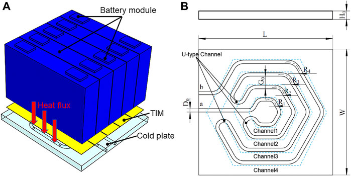
FIGURE 1. (A) Schematic diagram of battery cooling structure based on cobweb-like channel schematic (B) Diagram of cooling plate structure.
2.2 Battery heat generation model
The interior of the lithium-ion battery is composed of stacked cells. During the process of discharging heat, various heats such as reaction heat and Joule heat are involved. Complex chemical reactions, heat generation and thermal conductivity of materials need to be considered when calculating these amounts of heat. Therefore, a reasonable battery heat generation rate model needs to be established. In this paper, the widely used Bernardi battery heat generation rate mathematical model is used, and its heat generation rate equation is described by the following Eq. 1 (Bernardi et al., 1985). Without considering the operating conditions of battery abuse or thermal runaway state (limit state), based on the Bernardi battery heat generation and heat conduction theory, combined with the distribution law of the internal materials of the battery, the structure of the battery cell is appropriately simplified. It is assumed that the interior of the battery is a homogeneous material, the density, specific heat capacity, and thermal conductivity of the battery remain constant regardless of temperature and state of charge. Ignoring the convective heat transfer and heat radiation inside the battery is to focus on the heat transfer between the entire battery module and the cooling plate. The purpose is to balance the relationship between model accuracy and complexity.
Where q is the heat generation power of lithium-ion battery per unit volume, Vb is the volume of the heat generating part of the battery, I is the charge and discharge current, I2R represents the joule heat generated by the battery, R is the internal resistance of the battery, T(dE0/dT)I represents the reversible reaction heat generated by the battery, dE0/dT is the temperature coefficient, E0 is the open circuit voltage, T is the battery temperature.
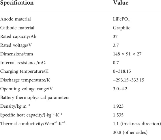
In this work, the technical specifications and thermophysical parameters of the selected rectangular lithium-ion battery are shown in Table 2.
2.3 Numerical solution
2.3.1 Computational fluid dynamics theory
To simplify the simulation, assume the following:
(1) The cooling plate is uniformly isotropic.
(2) The surface of the cooling plate except the upper surface is assumed to be adiabatic.
(3) The fluid is an incompressible stable fluid with constant dynamic viscosity, specific heat capacity and thermal conductivity and no internal heat source.
(4) The thermophysical properties of fluids and solids are independent of temperature.
(5) The effects of gravity, viscous dissipation and thermal radiation are ignored.
In addition, Reynolds number is an important parameter to judge the fluid motion state. The Reynolds number at the entrance of the cooling channel can be calculated according to Eq. 2, and the Reynolds number of the coolant is less than the critical Reynolds number 2,300. Therefore, the fluid motion model involved in this work is laminar flow model.
Where Re is the Reynolds number, ρc is the fluid density, Dh is the characteristic length, vc is the fluid velocity, μ is the viscosity coefficient of the fluid.
Based on the above assumptions, the governing equation of incompressible laminar flow without internal heat source is simplified as follows in steady-state conditions.
Continuity equation:
Momentum conservation equation:
Energy conservation equation:
Energy conservation equations for solids
Where u, x, and ∇ are the velocity vector, vector operator and gradient operator respectively in Cartesian coordinate system, ρ is fluid density, p is fluid pressure, μ is the dynamic viscosity of fluid, cp is specific heat capacity of fluid, λ is the thermal conductivity of the fluid, T is temperature.
The transfer of heat q between channel round surface and fluid can be calculated by Newton cooling formula, as shown in Eq. 7.
Where h is convective heat transfer coefficient, A is convective heat transfer area, Tw is the temperature of the round surface of the flow channel, Tl is the temperature of coolant.
For the sake of simplicity, the maximum temperature (Tmax) and temperature difference (ΔT) of the battery module will indicate the good or bad working condition of the battery. The larger the maximum temperature and temperature difference indicate the worse the working condition of the battery module and the worse the performance of the cooling plate. In addition, when the fluid in the channel is incompressible laminar flow, the pressure drop (ΔP) between the inlet and outlet of the cooling plate channel is shown in Eq. 8.
where v is the velocity of fluid, l is the length of channel along flowing-direction, ρ is the density of fluid, D is hydraulic diameter of the channel, f represents the friction factor. Pinlet and Poutlet are the total pressure of the inlet and outlet, respectively.
2.3.2 Grid independence test
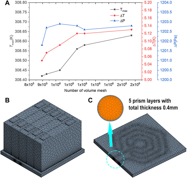
In the numerical simulation of computational fluid dynamics (CFD), the quality and quantity of meshes in the model have an important influence on the accuracy of the simulation, so obtaining a good mesh is the premise of simulation calculation. In this work, the grid module of STAR-CCM+ software is used for meshing. The polyhedral grid with excellent convergence, high computational accuracy and low memory consumption is used for the battery module, cooling plate and coolant, and the thin-body grid with two layers is used for the thermal interface material with small thickness. In addition, in order to obtain more accurate heat transfer simulation results, the fluid part of the coolant is encrypted, and five boundary layers are established at the intersection of the fluid and the cooling plate channel, with a total thickness of about 4% of the basic size (0.4 mm).
In order to determine the appropriate number of grids, the grid independence verification is carried out using the cooling plate structure in Figure 1B. First, six kinds of volume meshes with different numbers and mesh quality above 0.95 were generated by STAR-CCM+, and then numerical simulation was carried out under the same boundary conditions to the effect of the number of meshes on the maximum temperature (Tmax) of the battery module, the temperature difference (ΔT) of the module, and the pressure drop (ΔP) between the inlet and outlet of the cooling plate, the grid independence test results are shown in Figure 2A. The results show that when the grid number reaches 1160828 and the grid number is further increased, the changes of Tmax, ΔT, and ΔP are all less than 1%. This shows that the simulation results are independent of the volume mesh number. Therefore, considering the actual calculation conditions, the basic size of the grid is finally determined to be 0.01 m, the total number of grids is 1160828, and the grid quality is 0.98 (The best grid quality is 1). The meshed model is shown in Figures 2B,C.
2.3.3 Boundary conditions
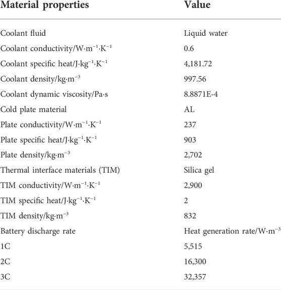
In this work, the inlet boundary is defined as the velocity inlet, which is set to 0.3 m⋅s−1, the temperature is set to 299.15 K, the outlet boundary is defined as the pressure outlet, which is set to 0 Pa. The cooling plate material is aluminum, the cooling liquid material is water, and the thermal interface material is filled between the battery module and the cooling plate to improve the heat exchange performance between the cooling plate and the battery module. The heat source of the battery is set as a volume heat source. The specific parameter values are shown in Table 3.
3 Results and discussion
3.1 Analysis and comparison
Under the discharge condition of 3C, the same boundary conditions are set, and the serpentine (S-type) and cobweb-like (C-type) channels in the two coolant flow directions (Ifd and IIfd) are respectively simulated. Therefore, the temperature field of the battery module, the cooling plate and the cooling liquid, and the pressure distribution of the cooling channel are obtained.
Figures 3A–C show the comparison of temperature distributions of battery modules. As shown in Figure 3A, the temperature of the surface of the battery module gradually increases along the flow direction of the cooling liquid, and there is an obvious temperature gradient. The lowest temperature is at the coolant inlet, its value is 302.95 K, the highest temperature is 309.18 K, and the temperature difference is 6.23 K. Therefore, the heat dissipation effect of the S-type cooling plate on the battery module is not ideal. Figures 3B,C show that the temperature distribution of the battery module using the C-type cooling plate. As shown in Figure 3B, the maximum temperature of the cooling liquid flowing to the battery module using Ifd dropped to 308.81 K, the temperature difference was 5.66 K, and the temperature distribution was improved to a certain extent. At the same time, as shown in Figure 3C, the temperature distribution on the surface of the battery with IIfd is more uniform, and the cooling effect of the battery is the best, the maximum temperature is 308.56 K, and the temperature difference also drops to 5.12 K.
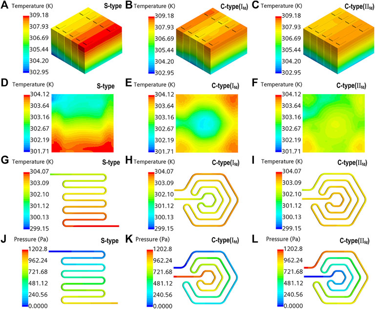
FIGURE 3. Surface temperature distribution of (A–C) battery module; (D–F) cold plate; (G–I) coolant. (J–L) Surface pressure distribution of cooling channel.
The temperature distribution on the surface of the cooling plate can indirectly reflect the cooling performance of the two structures (Deng et al., 2019; Yan et al., 2019; Fan et al., 2022). Figures 3D–F show the comparison of temperature distributions on the cooling plate surface. As shown in Figure 3D, the temperature distribution on the surface of the S-type cooling plate varies greatly, the maximum temperature is 304.12 K, the minimum temperature is 301.71 K, and the temperature difference is 2.41 K. The high temperature is mainly concentrated near the outlet of the channel, which is consistent with the temperature distribution of the battery module. As shown in Figures 3E,F, the temperature distribution on the surface of the cooling plate is more uniform than that of the S-type cooling plate. The higher temperature on the surface of the C-type cooling plate using Ifd is mainly concentrated in the corners, the highest temperature is 304.01 K, and the lower temperature is distributed in the middle of the cooling plate, the lowest temperature is 302.09 K, and the temperature difference is 1.92 K. And the maximum temperature with IIfd drops to 303.66 K, and the temperature difference drops to 1.5 K. Therefore, it is found that the flow direction IIfd makes the temperature of the cooling plate controlled within a small range, and the temperature distribution is more uniform, which is more conducive to the cooling plate to exert the best heat exchange performance, thereby ensuring the effective heat dissipation of the battery module.
Figures 3G–I show the temperature comparison of the coolant. For C-type, the maximum temperature and temperature difference of the coolant using IIfd are smaller, and the temperature distribution is more uniform, which is beneficial to reduce the temperature difference on the surface of the battery, so that the battery can exert better performance. The temperature distribution of the S-type coolant is polarized, and the outlet temperature is much larger than the inlet temperature, resulting in an excessive temperature difference, which will have a greater impact on the normal operation of the battery. In addition, as shown in Figures 3J–L, the pressure drops between the inlet and outlet of the cooling channel using Ifd and IIfd are 1,201.3 Pa and 1,202.8 Pa, respectively. Compared with the S-type cooling channel, the pressure drop increases by 176 and 178 Pa respectively, which are within the acceptable range.
3.2 Results under different factors
In order to get the influence rule of cooling channel diameter on battery heat dissipation, the flow direction of coolant is IIfd, the initial thickness of cooling plate is 10 mm, the spacing of cooling channel is 15 mm, and other boundary conditions are consistent. The diameter is taken as a single variable to conduct simulation analysis. As shown in Figure 4A, the cooling channel diameter has a great influence on the maximum temperature, temperature difference and pressure drop. Initially, as the diameter of the cooling channel increases, the maximum temperature, temperature difference, and pressure drop decrease rapidly, but as the diameter continues to increase, the rate of decline becomes significantly flat, indicating that the effect of diameter size begins to weaken. When the diameter is 7 mm, the maximum temperature of the battery module is basically the same as that of 6 mm, and the temperature difference has a slight increase. The reason is that the increase of the diameter reduces the temperature of the surface of the cooling plate, the temperature of the bottom of the battery module drops rapidly, but the temperature of the top does not change greatly, and the heat cannot be transferred in time under the condition that the thermal physical parameters of the battery remain unchanged, which makes the battery The temperature difference of the modules increases slightly.

FIGURE 4. Effect on the Tmax, ΔT and ΔP of (A) cooling channel diameter (B) cooling plate thickness; (C) cooling channel spacing.
In order to obtain the influence law of the thickness of the cooling plate on the heat dissipation of the battery, the cooling liquid flow direction adopts IIfd, the diameter of the cooling pipe is 6 mm, the spacing is 15 mm, and the rest of the boundary conditions are the same. As shown in Figure 4B, as the thickness of the cooling plate increases, the heat dissipation area of the cooling plate increases, and the heat dissipation efficiency also improves, so that the temperature difference of the battery module decreases significantly, but the maximum temperature does not change much. When the thickness of the cooling plate is 12 mm, the maximum temperature value of the battery module does not change much, and the temperature difference tends to be flat. In addition, since the pressure drop is not directly related to the thickness variation of the cooling plate, the pressure drop remains at the same level.
As shown in Figure 4C, when the diameter of the cooling channel is 6 mm and the thickness of the cooling plate is 11 mm, as the distance between the cooling channels increases, the maximum temperature on the surface of the battery module decreases gently, and the temperature difference decreases significantly. The analysis shows that the volume fraction of the cooling channel in the cooling plate increases, which increases the heat exchange area between the cooling plate and the cooling liquid, and improves the heat dissipation performance of the cooling plate to a certain extent. However, as the spacing continues to increase, when the cooling channel spacing is 17 mm, the temperature difference of the battery increases to a certain extent. In addition, the increase in spacing also causes the pressure drop to rise rapidly.
3.3 Cooling plate structure optimization
3.3.1 Orthogonal test
The analysis shows that three factors (cooling channel diameter, cooling plate thickness and cooling channel spacing) have an important impact on the temperature distribution on the surface of the battery module. In order to obtain the optimal structural parameters of the cooling plate, the orthogonal test method is used to optimize the structure of the cooling plate. The above three experimental factors are represented by letters A, B, and C respectively. According to the results of single-factor variable simulation, each experimental factor has five levels, and the L25 (53) orthogonal table is selected. The factor level table is shown in Table 4.
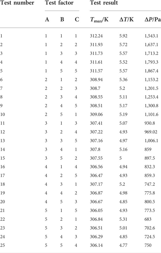
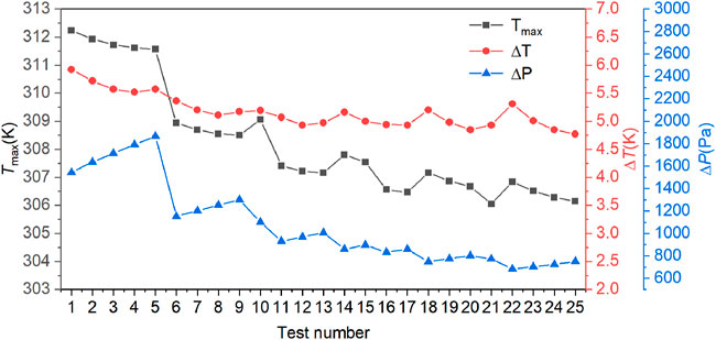
According to the orthogonal test scheme, the simulation models corresponding to each factor and each level are established respectively, and the Tmax, ΔT and ΔP are used as evaluation indicators. The results of orthogonal test as shown in Table 5. The trend of the whole orthogonal test results is shown in Figure 5. The maximum temperature is the smallest at test number 21, the temperature difference is the smallest at test number 25, and the pressure drop is the smallest at test number 22.
3.3.2 Range analysis
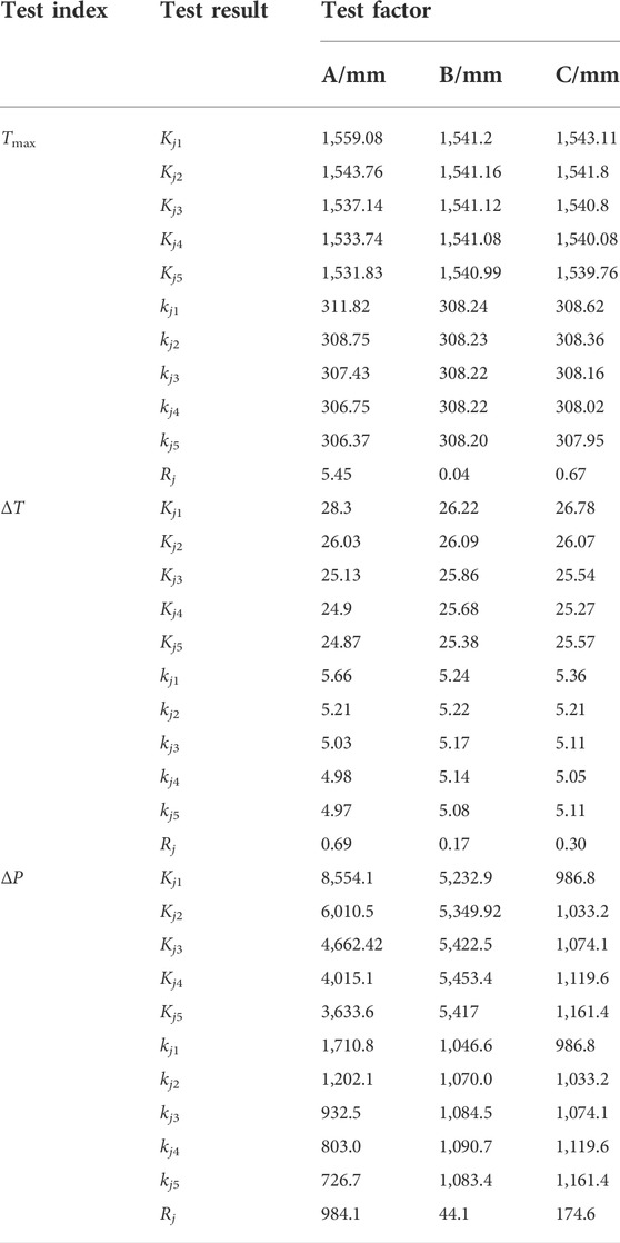
The range analysis method (R method) determines the degree of influence of factors in the orthogonal test on Tmax, ΔT, and ΔP. The larger the R value, the greater the influence of this factor on the test index. In this paper, Rj is used to represent the range value of the jth column factor. The specific calculation formula is described as follows (Pan et al., 2019):
Where Kjm is the test index sum corresponding to the m level of the jth column factor; kjm is the average value of Kjm; n is the number of test levels; (j = A, B, C; m = 1,2,3,4,5).
Table 6 shows the results of the range analysis. The order of the influence degree of the three experimental factors on Tmax, ΔT, and ΔP is consistent: A > C > B. The cooling channel diameter has the greatest influence on each index, followed by the cooling channel spacing, and finally the cooling plate thickness. For the maximum temperature index, the optimal factor level combination is A5B5C5, at which time the maximum temperature of the battery module is the smallest. For the temperature difference index, the optimal factor level combination is A5B5C4, at which time the temperature difference of the battery module is the smallest. For the pressure drop index, the optimal factor level combination is A5B1C1, at which time the pressure drop between the inlet and outlet of the channel is the smallest.
When evaluating the cooling performance of the cooling plate, it generally depends on the maximum temperature and temperature difference of the battery module. While meeting the battery cooling requirements to the greatest extent, it also has a reasonable voltage drop. According to the results of the range analysis, factor A has the greatest influence on the maximum temperature, temperature difference and pressure drop index. The optimal factor level is 5, so the cooling channel diameter is 7 mm. Factor B has the least impact on the three indicators. The optimal factor level for both the maximum temperature and temperature difference of the battery module is 5. At the same time, in terms of pressure drop, the optimal factor level for the minimum pressure drop is 1, but according to Figure 4B, it can be seen that the thickness of the cooling plate has little effect on the pressure drop, so the thickness of the cooling plate is 12 mm. The influence degree of factor C on the three indicators is the second. As shown in Table 5, the maximum temperature index values of level 4 and level 5 are not much different, but there is a large difference in the temperature difference index, so take the level 4 with the smaller temperature difference index value, so the cooling channel spacing is 16 mm. Finally, considering the three indicators comprehensively, the optimal combination of structural parameters of the cooling plate is determined as A5B5C4.
4 Conclusion
1) To promote efficient heat dissipation of the battery, a cooling plate with cobweb-like channel is designed. The novel structure is found to be effective in reducing the maximum temperature and temperature difference of the battery module through CFD modeling.
2) The comparison of the simulation results between S-type and C-type shows that the cobweb-like cooling plate has better heat dissipation, and the maximum temperature and temperature difference of the battery module are lower, but the channel pressure drop is slightly higher. Secondly, the flow direction of the coolant in this structure has an important effect on the heat dissipation of the battery module. Compared with Ifd, the overall temperature distribution of the coolant is more uniform with the IIfd flow direction, and the temperature difference on the surface of the cooling plate is smaller, thus the overall heat dissipation of the battery module is better.
3) When the cooling channel diameter is 3∼7 mm, the cooling plate thickness is 8∼12 mm and the channel spacing is 13∼17 mm, the performance of the cooling plate improves and the maximum temperature and temperature difference of the battery module decreases with the increase of the diameter, spacing and thickness. The orthogonal test results found that the best heat exchange between the cooling plate and the battery is achieved when the cooling channel diameter is 7 mm, the thickness of the cooling plate is 12 mm, and the spacing is 16 mm. In summary, the cobweb-like channel cooling plate provides a certain reference value for the study of thermal management of automotive power lithium-ion batteries.
Data availability statement
The original contributions presented in the study are included in the article/supplementary material, further inquiries can be directed to the corresponding author.
Author contributions
QZ provided the conception and design of the study and wrote the first draft. HW guided the study, supported the fund and revised the first draft. ZW and YF provided ideas for the statistics and processing of the data. WC provided resources and hardware support for the study.
Funding
This work was supported by the National Natural Science Foundation of China (51875419), Natural Science Foundation Youth Project of Hubei Provincial (2020CFB320), Scientific Research Ability Cultivation Fund Science and Technology Innovation Team Project of Hubei University of Arts and Science (2020kypytd007), Hubei Superior and Distinctive Discipline Group of “New Energy Vehicle and Smart Transportation”, Open Fund of Hubei Key Laboratory of Power System Design and Test for Electrical Vehicle (ZDSYS202201, ZDSYS202208).
Conflict of interest
The authors declare that the research was conducted in the absence of any commercial or financial relationships that could be construed as a potential conflict of interest.
Publisher’s note
All claims expressed in this article are solely those of the authors and do not necessarily represent those of their affiliated organizations, or those of the publisher, the editors and the reviewers. Any product that may be evaluated in this article, or claim that may be made by its manufacturer, is not guaranteed or endorsed by the publisher.
References
Al-Zareer, M., Dincer, I., and Rosen, M. (2019). A novel approach for performance improvement of liquid to vapor based battery cooling systems. Energy Convers. Manag. 187, 191–204. doi:10.1016/j.enconman.2019.02.063
Alipanah, M., and Li, X. (2016). Numerical studies of lithium-ion battery thermal management systems using phase change materials and metal foams. Int. J. Heat. Mass Transf. 102, 1159–1168. doi:10.1016/j.ijheatmasstransfer.2016.07.010
Behi, H., Karimi, D., Behi, M., Jaguemont, J., Ghanbarpour, M., Behnia, M., et al. (2020). Thermal management analysis using heat pipe in the high current discharging of lithium-ion battery in electric vehicles. J. Energy Storage 32, 101893. doi:10.1016/j.est.2020.101893
Bernardi, D., Pawlikowski, E., and Newman, J. (1985). A general energy balance for battery systems. J. Electrochem. Soc. 132 (1), 5–12. doi:10.1149/1.2113792
Choudhari, V., Dhoble, A., and Panchal, S. (2020). Numerical analysis of different fin structures in phase change material module for battery thermal management system and its optimization. Int. J. Heat. Mass Transf. 163, 120434. doi:10.1016/j.ijheatmasstransfer.2020.120434
Chung, Y., and Kim, M. (2019). Thermal analysis and pack level design of battery thermal management system with liquid cooling for electric vehicles. Energy Convers. Manag. 196, 105–116. doi:10.1016/j.enconman.2019.05.083
Deng, T., Ran, Y., Yin, Y., Chen, X., and Liu, P. (2019). Multi-objective optimization design of double-layered reverting cooling plate for lithium-ion batteries. Int. J. Heat. Mass Transf. 143, 118580. doi:10.1016/j.ijh-eatmasstransfer.2019.118580
Fan, Y., Wang, Z., Fu, T., and Wu, H. (2022). Numerical investigation on lithium-ion battery thermal management utilizing a novel tree-like channel liquid cooling plate exchanger. Int. J. Heat. Mass Transf. 183, 122143. doi:10.1016/j.ijheatmasstransfer.2021.122143
Huang, P., Verma, A., Robles, D., Wang, Q., Mukherjee, P., and Sun, J. (2018). Probing the cooling effectiveness of phase change materials on lithium-ion battery thermal response under overcharge condition. Appl. Therm. Eng. 132, 521–530. doi:10.1016/j.applthermaleng.2017.12.121
Huo, Y., Rao, Z., Liu, X., and Zhao, J. (2015). Investigation of power battery thermal management by using mini-channel cold plate. Energy Convers. Manag. 89, 387–395. doi:10.1016/j.enconman.2014.10.015
Imran, A., Mahmoud, N., and Jaffal, H. (2018). Numerical and experimental investigation of heat transfer in liquid cooling serpentine mini-channel heat sink with different new configuration models. Therm. Sci. Eng. Prog. 6, 128–139. doi:10.1016/j.tsep.2018.03.011
Kausthubharam, , Koorata, P., and Chandrasekaran, N. (2021). Numerical investigation of cooling performance of a novel air-cooled thermal management system for cylindrical Li-ion battery module. Appl. Therm. Eng. 193, 116961. doi:10.1016/j.applthermaleng.2021.116961
Li, Y., Du, Y., Xu, T., Wu, H., Zhou, X., Ling, Z., et al. (2018). Optimization of thermal management system for Li-ion batteries using phase change material. Appl. Therm. Eng. 131, 766–778. doi:10.1016/j.applthermaleng.2017.12.055
Lu, M., Zhang, X., Ji, J., Xu, X., and Zhang, Y. (2020). Research progress on power battery cooling technology for electric vehicles. J. Energy Storage 27, 101155. doi:10.1016/j.est.2019.101155
Pan, C., Tang, Q., He, Z., Wang, L., and Chen, L. (2019). Structure optimization of battery module with a parallel multi-channel liquid cooling plate based on orthogonal test. J. Electrochem. Energy Convers. Storage 17 (2). doi:10.1115/1.4045197
Patil, M., Seo, J., Panchal, S., and Lee, M. (2020). Numerical study on sensitivity analysis of factors influencing liquid cooling with double cold‐plate for lithium‐ion pouch cell. Int. J. Energy Res. 45 (2), 2533–2559. doi:10.1002/er.5946
Pradeep, R., and Venugopal, T. (2020). Experimental study of lithium-ion battery cooling using mixture of phase change materials. Int. J. Electr. Hybrid. Veh. 12 (2), 168. doi:10.1504/ijehv.2020.106354
Qian, Z., Li, Y., and Rao, Z. (2016). Thermal performance of lithium-ion battery thermal management system by using mini-channel cooling. Energy Convers. Manag. 126, 622–631. doi:10.1016/j.enconman.2016.08.063
Rao, Z., Qian, Z., Kuang, Y., and Li, Y. (2017). Thermal performance of liquid cooling based thermal management system for cylindrical lithium-ion battery module with variable contact surface. Appl. Therm. Eng. 123, 1514–1522. doi:10.1016/j.applthermaleng.2017.06.059
Rao, Z., Wang, Q., and Huang, C. (2016). Investigation of the thermal performance of phase change material/mini-channel coupled battery thermal management system. Appl. Energy 164, 659–669. doi:10.1016/j.apenergy.2015.12.021
Saw, L., Ye, Y., Tay, A., Chong, W., Kuan, S., and Yew, M. (2016). Computational fluid dynamic and thermal analysis of Lithium-ion battery pack with air cooling. Appl. Energy 177, 783–792. doi:10.1016/j.apenergy.2016.05.122
Sheng, L., Su, L., Zhang, H., Li, K., Fang, Y., Ye, W., et al. (2019). Numerical investigation on a lithium ion battery thermal management utilizing a serpentine-channel liquid cooling plate exchanger. Int. J. Heat. Mass Transf. 141, 658–668. doi:10.1016/j.ijheatmasstransfer.2019.07.033
Wilke, S., Schweitzer, B., Khateeb, S., and Al-Hallaj, S. (2017). Preventing thermal runaway propagation in lithium ion battery packs using a phase change composite material: An experimental study. J. Power Sources 340, 51–59. doi:10.1016/j.jpowsour.2016.11.018
Xie, J., Xie, Y., and Yuan, C. (2019). Numerical study of heat transfer enhancement using vortex generator for thermal management of lithium ion battery. Int. J. Heat. Mass Transf. 129, 1184–1193. doi:10.1016/j.ijheatmasstransfer.2018.10.018
Yan, Y., Yan, H., Yin, S., Zhang, L., and Li, L. (2019). Single/multi-objective optimizations on hydraulic and thermal management in micro-channel heat sink with bionic Y-shaped fractal network by genetic algorithm coupled with numerical simulation. Int. J. Heat. Mass Transf. 129, 468–479. doi:10.1016/j.ijheatmasstransfer.2018.09.120
Yang W, W., Zhou, F., Zhou, H., and Liu, Y. (2020). Thermal performance of axial air cooling system with bionic surface structure for cylindrical lithium-ion battery module. Int. J. Heat. Mass Transf. 161, 120307. doi:10.1016/j.ijheatmasstransfer.2020.120307
Yang Y, Y., Xu, X., Zhang, Y., Hu, H., and Li, C. (2020). Synergy analysis on the heat dissipation performance of a battery pack under air cooling. Ionics (Kiel) 26 (11), 5575–5584. doi:10.1007/s11581-020-03676-5
Yu, X., Lu, Z., Zhang, L., Wei, L., Cui, X., and Jin, L. (2019). Experimental study on transient thermal characteristics of stagger-arranged lithium-ion battery pack with air cooling strategy. Int. J. Heat. Mass Transf. 143, 118576. doi:10.1016/j.ijheatmasstransfer.2019.118576
Zhang, T., Gao, Q., Wang, G., Gu, Y., Wang, Y., Bao, W., et al. (2017). Investigation on the promotion of temperature uniformity for the designed battery pack with liquid flow in cooling process. Appl. Therm. Eng. 116, 655–662. doi:10.1016/j.applthermaleng.2017.01.069
Keywords: lithium-ion batteries, battery thermal management, cobweb-like channel, cooling plate, microchannel
Citation: Zhao Q, Wu H, Wang Z, Fan Y and Cheng W (2022) Numerical research on lithium-ion battery thermal management utilizing a novel cobweb-like channel cooling plate exchanger. Front. Energy Res. 10:992779. doi: 10.3389/fenrg.2022.992779
Received: 13 July 2022; Accepted: 25 August 2022;
Published: 15 September 2022.
Edited by:
Sheng S. Zhang, United States Army Research Laboratory, United StatesReviewed by:
Foster Kwame Kholi, Pusan National University, South KoreaQixing Wu, Shenzhen University, China
Copyright © 2022 Zhao, Wu, Wang, Fan and Cheng. This is an open-access article distributed under the terms of the Creative Commons Attribution License (CC BY). The use, distribution or reproduction in other forums is permitted, provided the original author(s) and the copyright owner(s) are credited and that the original publication in this journal is cited, in accordance with accepted academic practice. No use, distribution or reproduction is permitted which does not comply with these terms.
*Correspondence: Huawei Wu, d2h3X3h5QDE2My5jb20=
 Qian Zhao
 Huawei Wu
 Zhaohui Wang3
 Yiwei Fan
